Toll Fraud Device
We at 2600 are often asked, "What is a toll fraud device?" Well, we decided to answer the question once and for all. This Red Box is a toll fraud device. Why is it a toll fraud device? Because any Red Box that can be built this cheaply and this easily and can fit in the palm of your hand was clearly not made for demonstration purposes.
Okay, so what is a Red Box? Well... a Red Box is hacker slang for any device that simulates payphone coin signaling tones in North American payphones. Red Boxes emit the precise tones used by payphones to tell the local switch that the appropriate coinage has been inserted. The tones are played through the mouthpiece in lieu of dropping coins into the payphone. This particular Red Box is particularly fraudulent in that it only simulates quarter tones. After all, when one commits toll fraud one does not want to waste time pumping virtual nickels and dimes into the payphone when quarters work quite nicely thank you.
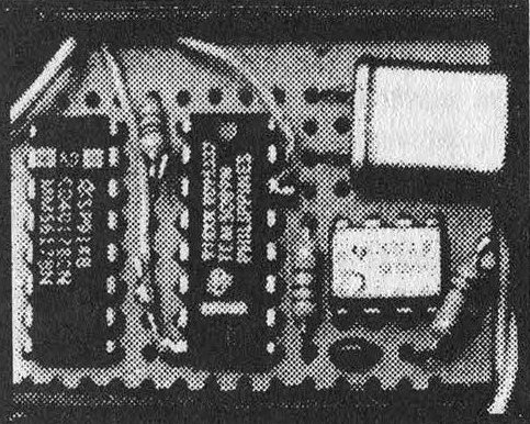
For those of you who are technically minded, the theory behind the circuit is easy enough to grasp. The DTMF encoder (U1) used in conjunction with the crystal (X1) produces the desired frequencies. The decode counter (U2) controls the cadence or how many frequency pulses are used. The 555 timer (U3) used in conjunction with R1, R2, and C1 produces the actual pulses and controls how fast they are delivered.
The circuit is a good hack because it utilizes the carry flag on U2 to overcome any stray charge on C1 that may cause the first pulse from U3 to be inaccurate. It accomplishes this by ignoring the first five pulses produced by U3, processing the next five, ignoring the third, processing the fourth, ignoring the fifth, etc... The circuit is also a good hack because it utilizes that well known coincidence in the DTMF encoder, the fact that substituting a 6.5 MHz crystal for a color-burst crystal (3.579545 MHz) just happens to raise the * key frequencies from 941 Hz and 1209 Hz to approximately 1708 Hz and 2195 Hz.
Since the desired frequencies for a quarter tone are 1700 and 2200 Hz, the output of the circuit is well within tolerance. The cadence is determined by the RC combination in U3. Each pulse lasts approximately 30 ms, followed by 30 ms of silence.
So fraudulent is this Red Box that we at 2600 have nicknamed it the Quarter. While all members of 2600 are morally righteous, and do not advocate the use of Red Boxes for fraudulent purposes, we must admit that if we ever did decide to commit toll fraud, we would trust nothing less than a Quarter to do the job.
Obviously, the Quarter will not work with Customer-Owned Coin Operated Telephones (COCOT). You may also have some difficulty with newer electronic payphones, as the phones companies are finally getting hip to these little devices and are isolating the talk path from the receiver until the call is established. Still, your Quarter should provide you with hours of fun-filled listening entertainment. In a world where a one minute payphone call from Washington, D.C. to New York costs $2.20 (at the maximum discount rate no less!) it will hardly surprise us at our suburban offices if, while sipping our afternoon tea, we happen to read about a sudden proliferation of Quarters across the U.S.
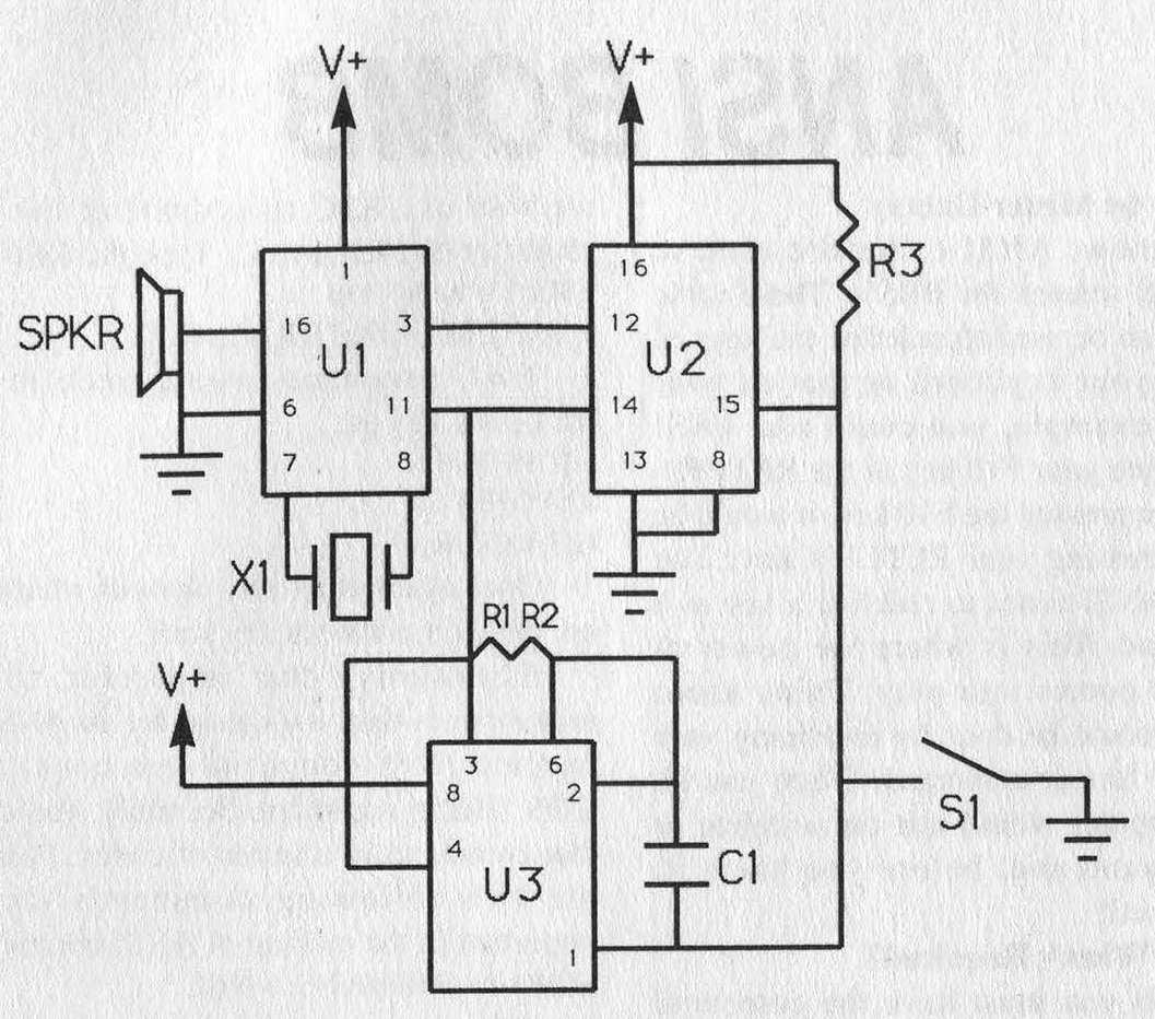
Note: All crossed lines on the diagram are points of connection.
Part List
Resistors Values Notes R1 220 kΩ The exact values of R1 & R2 are not important so long as their sum is 440 kΩ. R2 220 kΩ R3 1 kΩ Capacitors Values Notes C1 0.1 µF Keep leads short. Crystal Values Notes X1 6.5 MHz 6.5536 MHz is also within tolerance. Chips (IC) Name Notes U1 TCM5089 DTMF Encoder U2 74HC4017 Decade Counter (Regular CD4017 is O.K.) U3 TLC555 Timer IC (Regular 555 is O.K. if a 1 kΩ resistor is inserted between pins 3 & 8) Speaker Impedance Notes SPKR 600 ohms U1 expects an equivalent load. Switch Type Notes S1 Momentary You may also want to add a power switch. |
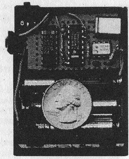
As printed the circuit expects three "AAA" batteries for a total of 4.5 volts. A 9-volt battery may also be used, but R1 and R2 should then total 470 kΩ instead of 440 kΩ. Obviously, you will need a perf-board and chassis if you expect to build the circuit. Parts may be ordered from electronics firms. Remember to order at least two of everything so that you will have spares in case you mess up.
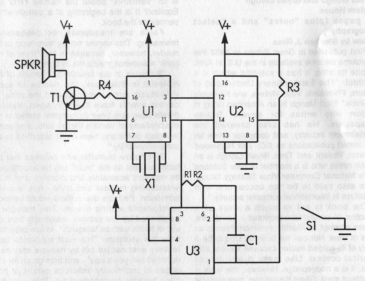
In keeping with our tradition of screwing up nearly every circuit diagram we've ever printed, we're happy to report that last issue's Quarter schematic did indeed contain an error: pins 3 and 8 on U3 should not be connected. While the error prevents the circuit from operating correctly, it should not have damaged the chips in any way.
Other readers expressed frustration with trying to obtain a 600 ohm speaker. We admit that the speaker is somewhat obscure, but it was necessary in order to keep circuit parts at a minimum. For the record, we were able to use a Kobitone dynamic microphone element (part number 25LM035 from Mouser Electronics) rated at 30 ohms. It is possible to use more common speakers such as those rated at 8 ohms, however, not without the addition of an op-amp to match U1's expected impedance.
The above schematic is a simple variation of the one we printed in our last issue. Readers will note that the original error is corrected (pins 3 and 8 on U3 are not connected), and that the circuit contains two additional parts: T1, a 2N2222 NPN transistor (although any NPN transistor should work); and R4, a 1 kΩ resistor. These parts comprise a simple op-amp that will allow virtually any low impedance speaker to be used.
We were able to purchase all our parts collectively from the following firms: Digi-Key Corporation (800-344-4539); Mouser Electronics (800-346-6873); and Southpaw Electronics (800-851-8870).