Build a Tone Tracer
by Mr. Upsetter
If you have ever browsed through catalogs of telecommunications equipment, you have probably seen a device called a "tone tracer." These little devices cost around $30 and are used by telco linepersons. The main function of a tone tracer is to place a tone on a telephone cable pair so the pair can be physically tracked or easily identified when in a large cable bundle. A tone tracer also can be used to check the polarity of a phone line, roughly measure continuity, and provide "talk power." You can build your own tone tracer from a handful of parts for just a few dollars.
Circuit Description and Operation
Please refer to the schematic diagram.
The circuitry basically consists of two parts: a tone generator and an amplifier. The tone generator can generate either a steady tone or a warble tone.
CD4001 NOR gates IC1c and IC2d along with C2, C3, R2, R3, and R4 create the tone.
Gates IC1a and IC1b are used to switch between steady and warble tones.
C1 and R1 control the rate of the warble tone. The frequency of the steady and warble tones is controlled by C2, C3, R2, R3, and R4.
Q1 and Q2 form a push-pull amplifier whose tone output is capactively coupled the phone line by C4.
When switch S2 is set to TONE, the 9V battery powers the tone generating and amplifier circuitry. If the tone tracer is connected to a speaker or a phone line, a loud tone will be heard. When S1 is set HIGH, there will be a steady tone. When S1 is set LOW there will be a warble tone.
When S2 is set to CONT, the 9V battery is connected to D1, R7, and R8. The device now functions as a basic continuity checker.
The brightness of the LED will vary with the resistance that is connected across the tone tracer. Also, when connected to a phone line, the tone tracer now provides talk power. If the phone line is completely dead (there is no voltage whatsoever on the line), then the tone tracer will provide enough voltage to power a couple of lineman's handsets or basic phones. This way communications can take place over short distances.
When S2 is in its center (OFF) position, the battery does not power the circuit at all. However, when the tone tracer is connected to a phone line, R7, D1, and R8 are connected across the phone line. Now the polarity of the line can be checked.
If the alligator clip marked RING is connected to the RING (-48V) side of the line, and the alligator clip marked TIP is connected to the TIP (ground) side of the line, the LED will light. If the clips are reversed, the LED will not light. Typically, the TIP wire is GREEN and the RING wire is RED.
Also, note that when connected with the correct polarity, the LED will be bright when the line is on-hook and dim when off-hook. When a ringing signal is present, the LED will flash.
Construction, Testing, and Tracing
Construction of the tone tracer is fairly straightforward and doesn't require any specific layout. You will probably want to solder it together on a small breadboard so it can be built into a compact, handheld enclosure. For convenience, you may want to connect a phone plug as well as alligator clips to the output of the tone tracer, Also, you may want to use a socket for the IC. All parts are available from Mouser Electronics. Call 800-246-6873 to get your free catalog.
After you have constructed your unit and double-checked all the connections, connect it to a small speaker and switch S2 into the TONE position. You should hear a rather obnoxious tone. Toggle S1 to make sure you get both warble and steady tones. Then disconnect the speaker, connect the tone tracer to a phone line, lift your phone off-hook, and do the same thing. The other minor functions should be easy for you to check out on your own.
Tone tracers are designed to be used with an inductive pickup of some sort. Inductive tracing is advantageous because no physical connections need to be made to the line, thus no wires need to be cut, no clips need to be hooked onto terminals, etc. It makes the job quicker and simpler.
To trace the tone of our tone tracer, you could spend $40-60 on a "line probe" type inductive pickup designed for the purpose. But since you went out and built your own tone tracer from scratch in the first place, you probably don't want to do that.
A marginal alternative is to use a basic audio amplifier (such as RadioShack 277-1008) and a suction cup pickup (RadioShack 44-533).
Connect the tone tracer to a phone line and switch S2 to TONE. You will be able to hear the tone when the pickup is placed very close to the cable or its terminal block. Winding 1 or 2 turns of the cable around the pickup should improve things. Unfortunately, this setup is vulnerable to 60 Hz noise from electrical wiring. You will need to rotate the pickup for the least amount of buzzing.
Parting Words
A tone tracer is a handy thing to have at times.
So instead of shelling out some cash to Specialized Products or Jensen Tools, you can build this simple, cheap circuit. But for those of you who are not electronically inclined, there is an even easier and cheaper way.
In most areas, there is a test number you can dial that puts a loud 1004 Hz tone on your line. For instance, in certain parts of California this number is your prefix plus 0002. Of course, you need to know the test number in your area to take advantage of this.
Tracer Schematic Diagram and Parts List
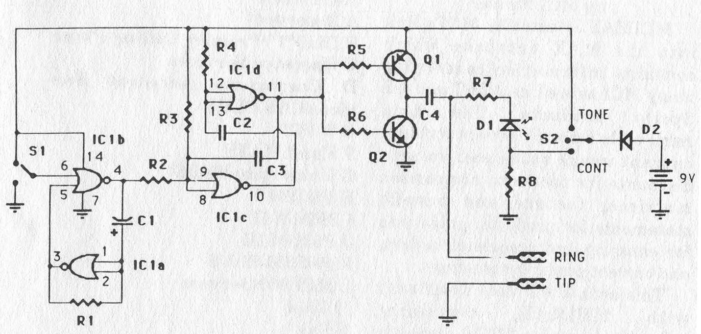
C1: 0.47 µF electrolytic C2: 0.01 µF; ceramic C3: 0.01 µF; ceramic C4: 0.1 µF; film (non-polarized) / 100V D1: LED (any color) D2: 1N4004 Q1: MPSA92 PNP Transistor Q2: MPSA42 NPN Transistor R1: 1 MΩ, 1/4W R2: 470 kΩ, 1/4W R3: 100 kΩ, 1/4W R4: 100 kΩ, 1/4W R5: 100 kΩ, 1/4W R6: 100 kΩ, 1/4W R7: 1 kΩ, 1/4W R8: 8.2 kΩ, 1/2W S1: SPDT Toggle Switch S2: ON-OFF-ON (Center Off Toggle Switch) IC1: CD4001 CMOS quad-NOR Additional Parts * Large alligator clips * Modular phone plug * 9V battery and clip * IC socket * Enclosure * PCB |