Dishal Crystal Ladder Upper and Lower Sideband Filters
The design of classic crystal ladder filters, for the lack of a more appropriate title, has been covered very well by Wes Hayward (1 and 2) and others. These have all been of the lower sideband type which is characterized by the high frequency slope being sharper than the low frequency slope. One problem with these designs is that the formula does not take into account the parallel capacitance of the crystal, essentially treating them as a pure series resonant circuit. As a result the performance does not precisely match the design specifications.
Figure 1. Classic LSB filter.
For the typical design shown above was specified as having a 2000Hz bandwidth.

Figure 2. Analysis of the filter of Figure 1.
However, analysis shows the actual response is only about 1500Hz. This is easily solved by specifying a bandwidth larger than required, by trial and error, until the desired bandwidth is achieved. Other methods of compensating for crystal parallel capacitance are described in references (3 and 4).
In 1963 an important transformation was described by M. Dishal (5). This transformation does take into account the parallel capacitance of the crystals and thus produces filters whose designs exactly match the specifications. Additionally it includes a transformation for Upper Sideband filters as well as Lower Sideband filters. Actually, it does not take the parallel capacitance into account but does require a capacitor across the crystal from which the crystals parallel capacitance can be subtracted thus removing it from the filter response. The amateur radio community was introduced to the Dishal USB filters by John Pivnichny, N2DCH in Comunications Quartely (6).
The equations for the Dishal filters is considerably more complex than the classics but that is not a problem thanks to the availability of a FREE filter design and analysis program (7).
The key variable in the transform is a quantity, 1/r0v3, which sets the spacing between the infinite rejection frequency and the center of the passband. These two frequencies are shown on the upper sideband filter of Figure 3.
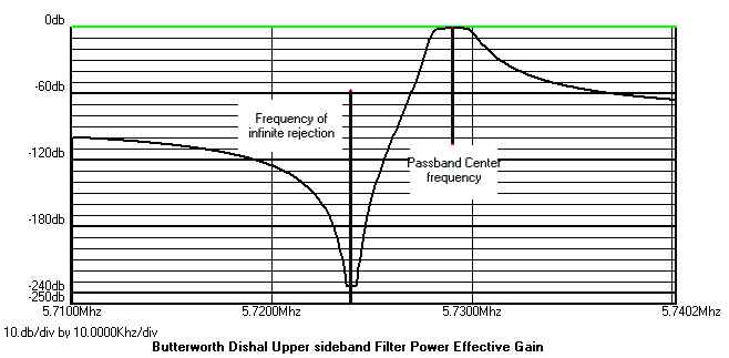
Figure 3. Frequencies used in defining the transformation variable 1/r0v3
By specifying various values of 1/r0v3 the passband center frequency can be controlled with some interesting results. 1/r0v3 has limits on it's value. If you exceed those limits negative component values will be calculated. The program will alert you if that happens and suggest what to do. Typically values range from 2 to 10 and need not be integers.
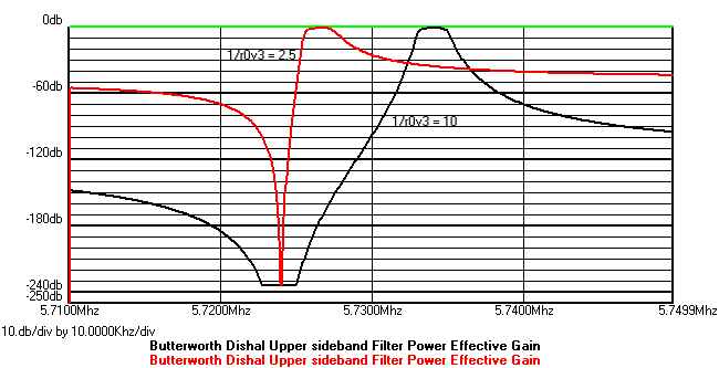
Figure 4. Comparison of results using extreme values of 1/r0v3
For these upper sideband filters low values of 1/r0v3 cause steep slopes on the low frequency side with less attenuation on the high frequency side. High values decrease the low frequency slope and increase the high frequency slope and stopband rejection. A value of 1/r0v3 = 5 is a good starting point. Note that the bandwidth is the same for any value of 1/r0v3. These plots are actually much better than they appear because the attenuation scale is 250db. Looking at the first 60db, is a more practical thing to do and the curves look better there, particularly at higher values of 1/r0v3. Compare Figure 5 with Figure 1 of a classic filter and they are very similar in performance except the Dishal filter bandwidth is 2000Hz, exactly as specified.
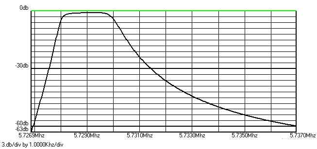
Figure 5. 60db attenuation plot of USB filter with 1/r0v3 = 5
The schematics of these filters can be a little more complex than the classics.

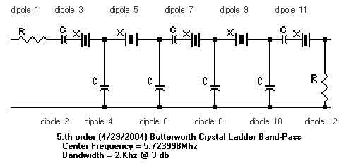
Figure 6. Schematic of 6th order upper sideband filter.

Figure 7. Schematic of 6th order lower sideband filter.
Designing pairs of Dishal USB and LSB filters using identical values of 1/r0v3 can give some interesting possibilities.
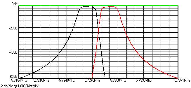
Figure 8. Dishal LSB and USB filters with 1/r0v3 = 5.
A matched pair of 2KHz bandwidth SSB filters can be produced centered about 5.7277 MHz. All crystals, in both filters, are identical from a batch with a series resonance of 5.724MHz. A spare crystal from the batch can be selected to produce the carrier frequency. A value of 5 for 1/r0v3 may not be correct for all crystal frequencies but a little trial and error should produce a similar pair of filters for whatever crystal you may want to use. The higher the frequency of the crystal the greater the latitude in choice of 1/r0v3.

Figure 9. Dishal LSB and USB filters with 1/r0v3 = 3.2
Using a 1/r0v3 = 3.2 produces a pair of overlapping filter responses.
One function the program provides is the ability to cascade two filters in series. Cascading the USB and LSB filters takes advantage of the sharp slopes of both. (Figures 6 and 7 in series)
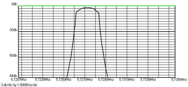
Figure 10. Cascaded Dishal LSB and USB filters with 1/r0v3 = 3.2
This cascade filter uses 12 crystals but produces a interesting response. A value of 3.2 for 1/r0v3 may not be correct for all crystal frequencies but a little trial and error should produce a similar pair of filters for whatever crystal you may want to use. The two filters do not have the same source and load impedances but apparently disregarding that has little negative effect.
My experience with filters is limited to the theory of design and analysis, not with practice. The program uses extremely precise component values but, if sufficiently accurate components are used, results very close to the theoretical should be obtainable. Accurate measurement of the crystal parameters is important. Procedures are described in the excellent book "Experimental Methods in RF DESIGN" (8) obtainable from the ARRL library. A nifty tester was described by Doug DeMaw in QST (9).
The program allows you to manually change the value of any component so you can plug in closest standard values and analyze their effect on the response. The program also has statistical analysis that will automatically change values over a limited percentage plotting the range of results for randomly selected parts.
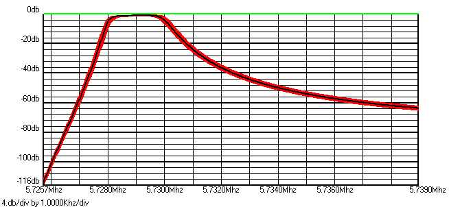
Figure 11. Monte Carlo analysis where all capacitors are randomly varied +/-5%.
The red band is the range of results with the black precise result in the middle. This shows the design is relatively tolerant of component values.
1) Designing and Building Simple Crystal Filters. Wes Hayward W7ZOI QST July 1987
2) A Unified Approach to the Design of Crystal Ladder Filters, Wes Hayward, W7ZOI , QST May 1982
3) Systematic Design of Crystal Ladder Filters, Worthie Doyle, N7WD, Ham Radio, February 1982.
4) Ladder Crystal Filter Design, J.A. Hardcastle, G3JIR, QST, November 1980.
5) Modern Network Theory Design of Single-Sideband Crystal Ladder Filters, M. Dishal, Proceedings of the IEEE December 1963
6) A Different Approach to Ladder Filters, John Pivnichny, N2DCH, Communications Quartely, Winter 1991.
7) AADE Filter Design and Analysis. Download FREE from www.aade.com
8) Experimental Methods in RF DESIGN, Wes Hayward, Rick Campbell, Bob Larkin, ARRL press 2003.
9) A tester for Crystal F, Q and R, Doug DeMaw, QST January 1990
appendix
AADE FILTER DESIGN AND ANALYSIS FUNCTIONS
DESIGN
ANALYSIS frequency domain
ANALYSIS time domain
STATISTICAL ANALYSIS
UTILITIES
You can specify a Qu for inductors and get response plots for real world components.