Motorola iDEN & The USRP

Introduction:

Integrated Digital Enhanced Network (iDEN) is a Motorola land mobile digital data transmission technique for voice and data. Various land mobile radio radio companies (such as Southern Linc) and cellular telephone companies (especially Sprint-Nextel) run regional and nationwide iDEN networks. iDEN voice services are perhaps best known for their push to talk functionality, a direct reflection of the original land mobile business service niche iDEN was designed to fill. Data services can include wireless email and internet access for computers and Blackberry units.

From a U.S. regulatory perspective iDEN networks are not considered cellular phone systems and are licensed to operate on 800MHz SMR frequency allocations (851 - 869 MHz band for towers; 806 - 824 MHz for mobiles). Thus they do not enjoy any of the special protections afforded cellular phone systems transmissions. So while a private citizen is not permitted to monitor cellular phone traffic it remains perfectly legal to monitor the exact same type of traffic on an iDEN network.

Outside the U.S. iDEN may be known as DIMRS (Digital Integrated Mobile Radio Service).  Interestingly enough a search using the DIMRS keyword generally returns information on intimate feminine body accoutrements (such as here, here, or even on eBay)...  who says engineers don't have a sense of humor?

From an orthographic perspective iDEN like eBay is an example of lowerCamelCase (but not CamelToe).

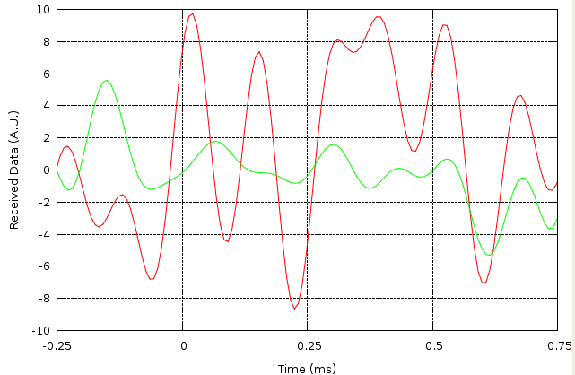
This page shows some iDEN data transmission samples collected using ETTUS Research USRP hardware and GNU Radio software.


Some iDEN Data Transmission Characteristics:
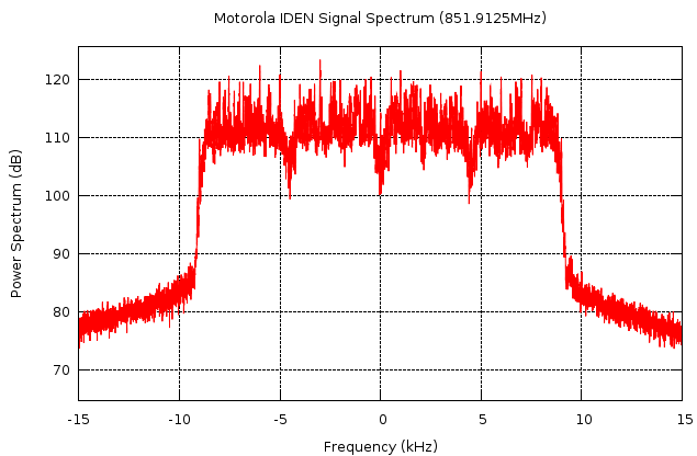
The transmission format is designed for 25 kHz channel spacing. Data is transmitted using four 16QAM modulated sub-channels; with each sub-channel carrying 4000 symbols / second we end up with a total raw bit rate of 64 kbits/sec.  The channel throughput then comes out to very roughly 3 bits/sec/Hz.

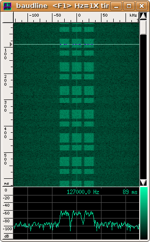
The following shows a typical iDEN spectrum:

iDEN Spectrum
Above: iDEN signal spectrum.  The individual sub-channels spaced at ±2250 and ±6750 Hz relative to the center of the RF channel are readily apparent.

One designates the four sub-channels LO (Left Outer), LI (Left Inner), RI (Right Inner), and RO (Right Outer) in order of increasing frequency as shown in the following table:

Sub-Channel

Offset relative to carrier center

LO

- 6750 Hz

LI

- 2250 Hz

RI

+ 2250 Hz

RO

+ 6750 Hz


Symbol filtering uses the Root Raised Cosine (RRC) response with roll-off factor α = 0.2. 
The 4000 symbol / second rate is low enough that one does not have to worry about channel equalization.


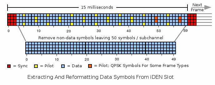
iDEN Frame Structure:
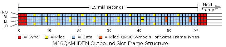

iDEN data is transmitted in 15ms time slots.  The precise start of a time slot can be determined by detecting the sync symbol sequence.  Demodulation of data symbols is assisted by pilot symbols of known magnitude and phase.  All together a typical iDEN outbound slot looks like:

iDEN Frame Structure, Outbound Slot
Above: Arrangement of an iDEN frame showing sync, pilot, and data symbols.  Pilot demodulation techniques and slot structures are described in U.S. Patents 5,519,730; 6,873,614; and 6,909,761.

Note that sync bursts can also serve as pilots and therefore an iDEN frame is always terminated with a sync burst (even if there is no following frame).  Also note that split outbound slot types transmit QPSK data on some pilot symbols; the pilot symbols can still be used as pilots since the expected magnitude is constant and the expected phase can be easily derived from the received symbol.

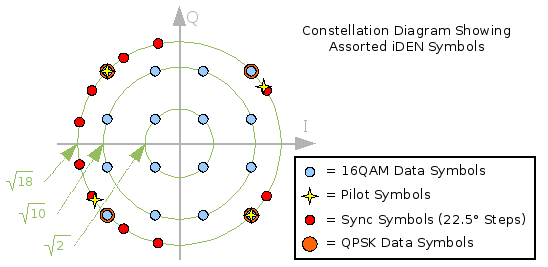
While all sync and pilot symbols have the same (maximum) amplitude they will have varying phases.  Essentially these symbols can be viewed as lower order phase modulated symbols:

Sub-channel RO

Sub-channel RI

Sub-channel LI

Sub-channel LO

Symbol #

Phase (°)

Symbol #

Phase (°)

Symbol #

Phase (°)

Symbol #

Phase (°)

0

-31

0

+102

0

-102

0

+31

1

-31

1

-123

1

+123

1

+31

2

+149

2

-168

2

+168

2

-149

5

+34

9

-45

9

+168

5

-21

13

-146

17

+135

17

-12

13

+159

21

+34

25

-45

25

+168

21

-21

29

-146

33

+135

33

-12

29

+159

37

+34

41

-45

41

+168

37

-21

45

-146

49

+135

49

-12

45

+159

53

+34

57

-45

57

+168

53

-21

60

-121

60

-168

60

+168

60

+121

61

-121

61

-33

61

+33

61

+121

62

+59

62

-78

62

+78

62

-59

Sync symbols are shown in red, pilot symbols in yellow.  Orange symbols may also be pilots carrying QPSK data.

Symbol locations are numbered from 0 (first sync symbol position on left) through 59 (last data symbol position on the right).

Technically symbols 60, 61, 62 belong to the next time-slot but they are shown above because they can be used as pilot references too.  Note the phase shifts caused by 60 symbol times (60 * 0.25ms = 15ms) on the 2250Hz and 6750Hz sub-carrier frequency offsets come out to plus and minus 90 degrees.  When we move to the next iDEN slot 15ms later symbols 60, 61, and 62 slide to positions 0, 1, and 2 with the phases as shown above.


Data symbols carry 4 bits of information in a 16QAM constellation.  Putting it all together we have:

Expected iDEN constellation structure
Above: iDEN sub-channel data symbol constellation with circles representing one of three possible symbol amplitudes.  Sync and pilot symbol locations also shown.

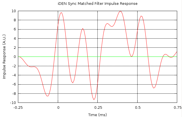
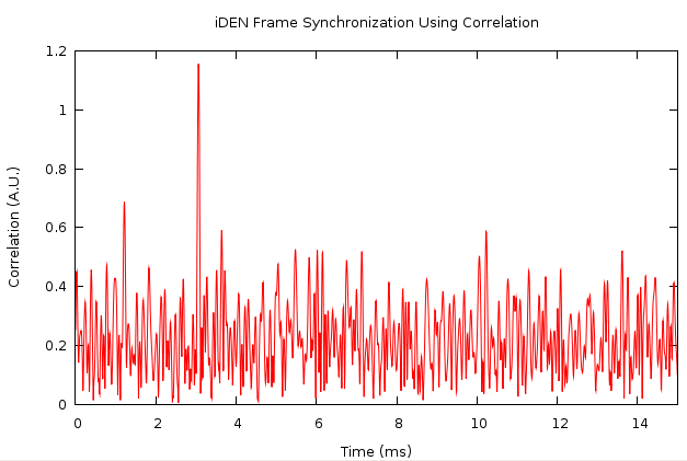
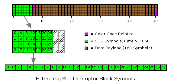
Getting In Sync With The iDEN Frame:


U.S. Patent 5,343,499 details how one may efficiently detect synchronization sequences in iDEN systems.  The basic idea is that the sync symbols collectively form a response waveform suitable for detection by matched filter correlation techniques.  By choosing a symmetric set of sync symbols one ends up with a purely real waveform (no quadrature component) which simplifies processing.
 
So first we need a matched filter response.  We create the appropriate sync symbol impulses for each sub-channel, RRC filter them (symbol rate 4000Hz, alpha = 0.2), frequency shift each sub-channel ±2250Hz or ±6750Hz as appropriate, and add everything together to get the following:

Calculated iDEN Sync Waveform
Above: Calculated sync symbol waveform.  In phase component shown in red; quadrature in green.  The quadrature component has become all zeros as expected.  Sync symbols are at t = 0, 0.25, and 0.5 ms.

We compare with some received data to verify we did our math correctly:

Actual Received iDEN Sync Waveform
Above: Actual received iDEN waveform centered on start of frame.  We have a good match with the calculated waveform in the region where the sync symbols are located.

So far so good.  Let's give our matched filter a try on some actual data.  We will use a 15ms window to ensure we get one and exactly one correlation peak indicating the start of the iDEN frame:

iDEN Frame Sync Via Correlation
Above: Successful Detection of iDEN frame start using correlation techniques.  Frame start has been found at ~3ms into the sampled data.

Perfect.  We are now able to reliably detect the start of iDEN frame with an accuracy better than 10 micro-seconds.


Extracting iDEN Data:
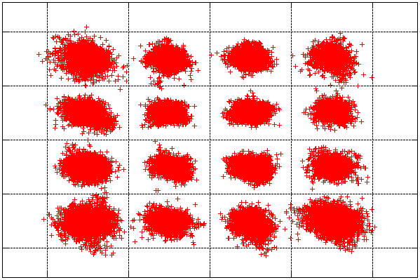

Extracting data
involves processing each iDEN sub-channel independently.  We shift each sub-channel to zero frequency and then apply the RRC symbol filter (symbol rate = 4000Hz; alpha = 0.2).  We linearly interpolate between the known pilot positions to create amplitude and phase references for each data symbol.  We can then correct each data symbol and map it to a position in the bit constellation.

We check everything is working correctly with a constellation diagram:


Good M16QAM Constellation
Above: Two seconds worth of iDEN data.  All four sub-channels plotted together.  Nice clean constellation with low bit error rate on received data.

The phase shift errors of the sync and pilot symbols of a received frame can be used to derive a frequency error which can be fed back for fine tuning.  This works very well for plus or minus a few hundred Hz but anything larger starts running into problems caused by the RRC symbol filtering being too far off.  So a different coarse tuning step is required to get the received frequency correct within a few hundred Hz.


Also of interest - iDEN is quite sensitive to system nonlinearities.  For example, the beautiful constellation diagram above can sometimes turn into this catastrophic state:

Distored M16QAM Constellation
Above: M16QAM constellation distortion caused by non-optimal USRP gain setting.
Please think of the children - avoid this situation!!!

One can always check the received signal with the usrp_fft.py sample program & ensure one is in the linear range by verifying USRP gain adjustments move the displayed spectrum up and down in tandem.  One must find a good compromise gain that avoids nonlinear gain compression on the high side while also avoiding having the signal sink into the noise floor on the low side.  But that's the price you pay for a 12 bit dynamic range.


Extracting iDEN Slot Descriptor Block Control Data:

Caution: Information in this section is preliminary and may be subject to correction.

Now that we are successfully receiving iDEN data slots it is time to turn our attention to the information being transmitted.  As a first step we discard all non-data symbols from the received time slot and reformat the bits into four contiguous sets of fifty symbols each (one for each subchannel).  Depicted graphically:

iDEN - Tossing away all non-data bits

At this point we will separate out the Slot Descriptor Block (SDB), a control data stream which consists of identification, timing information, payload modulation type, and similar status bits.
  Every iDEN slot has this SDB header regardless of the data payload.  Not a big surprise really since it is this very header that tells us what the data payload.  Outside of the SDB we have the data payload and four color code symbols.  The color codes are a fixed identifier transmitted by each base station to allow discrimination of the received signal from neighboring base stations that may share the same frequency.

We find there are 28 symbols devoted to the SDB.  We number the symbols from 0 to 27 inclusive and show their location relative to the entire data field:

Location of Slot Descriptor Block data symbols

Note that no fancy data interleaving is used.  We seem to have everything we need to successfully run the Viterbi algorithm on the received control data stream using rate ½ Trellis Coded Modulation (TCM).  Each QAM symbol is constructed from two dibits (one each for the I & Q phases) with each dibit containing one bit of information; the control channel data is a stream of these IQ IQ IQ ... symbols. 

We convert our received control data symbols into a binary data stream using the following table:


Rate ½
Dibits

I
-3
-1
+1
+3
Q

+3
10 01
11 01
01 01
00 01
+1
10 00
11 00
01 00
00 00
-1
10 10
11 10
01 10
00 10
-3
10 11
11 11
01 11
00 11

The above symbol mapping produces something that keeps the Viterbi algorithm happy when used with figures 6 and 7 of U.S. Patent 5,754,734.  The initial and ending states are both zero as expected and there are three zero flush bits.  So it looks like we have characterized the rate ½ TCM correctly.  It is an interesting but somewhat pointless observation that wrong symbol mappings can also produce data streams that can be run happily through the Viterbi algorithm but require non-zero initial and final states along with some non-zero flush bits which should be taken as an indicator that something is wrong.

For reference we show what has been derived from figures 6 and 7 of U.S. Patent 5,754,734 and what we have attempted to apply to the SDB:

Current State
Input Bit = 0
Input Bit = 1
0
0
1
1
2
3
2
4
5
3
6
7
4
0
1
5
2
3
6
4
5
7
6
7
TCM state transition table - new state as function of current state and input bit.  Follows U.S. Patent 5,754,734 Fig. 6.

Current State
Input Bit = 0
Input Bit = 1
0
01
10
1
00
11
2
10
01
3
11
00
4
10
01
5
11
00
6
01
10
7
00
11
Emitted symbol as function of TCM state and input bit.  Follows U.S. Patent 5,754,734 Fig. 7.


When all is said and done we end up with 53 SDB data bits (not counting the 3 flush bits).  But there is one further complication: parts of the SDB data fields appear to be xor'ed with the slot number (or more likely a data whitening sequence).


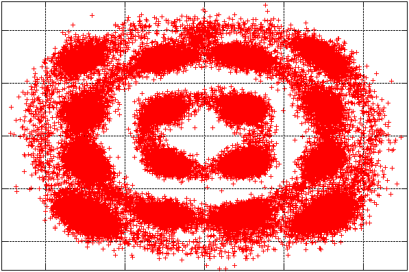
Ganging iDEN Channels Together:


The original impetus for ganging iDEN channels together was to increase potential packet data transmission throughput.  With up to four channels in tandem a 4x increase in potential data throughput can be realized.  Further throughput increases are achieved by going moving to higher order modulation formats (M64QAM) as channel conditions permit; with better reliability by dropping to QPSK when conditions dictate.  These enhancements are known as "wiDEN".

We suspect this is the reason iDEN channels like to show up in clusters.  As shown in the following time-frequency graph:

Spectrum of triple iDEN Base Station Transmission

Above: Time-frequency analysis of iDEN base station transmission utilizing 3 x 25 kHz channels. There is one 3:1 TDMA transmission (active timeslot every 45ms) and one 6:1 TDMA transmission (active timeslot every 90ms).

It appears as though individual channels cannot be independently turned on or off.  Either every channel is off or every channel is on even if there is nothing to transmit.  In this example 2/3rds of transmitted slots are split outbounds with idle data.

Screenshot made using baudline signal analysis software examining a raw USRP / GNU Radio over the air data capture.


iDEN Idle Data:

Care must be taken to discriminate iDEN idle conditions from actual data.  During idle states iDEN channels transmit pseudo-random sequences for signal time of arrival measurements.  When samples from multiple base stations are combined the physical location of the handset can be determined (U.S. enhanced 911 mandate related?).  For more details refer to U.S. Patent 6,396,825.

In a nutshell, the pseudo-random data consists of a fixed 47 word (16-bit) long circular buffer common to all devices. A starting position is calculated based on the base station color code and current time slot code.  41 consecutive words are then transmitted as the timeslot data payload under idle conditions. 
Sometimes this sequence appears as filler on an apparently unused half of a split outbound time slot.

A pedestrian inspection of iDEN transmissions quickly reveals the entire pseudo-random sequence.  This may then be used to cross-check color code and time slot codes.  It is also of some use in recognizing unused data fields but that is better handled by examining various fields elsewhere in the slot.

Next Steps:


Slot Descriptor Block data field characterization  + Cross checking + more iDEN trellis coding modulation + higher level protocols.

Somewhat further out: DVSI AMBE3000 decoder project for iDEN AMBE+2 6:1 voice codec.  VSELP codec work needed too.


Closing Comments:

M16QAM based radio systems have been designed and deployed in other parts of the world.  As an example, U.S. Patent 5,724,388 describes test equipment and protocols for a Japanese system (presumably iDRA) using a physical layer very similar to iDEN.

The techniques explored on this page are expected to be directly applicable to the APCO-34 (TIA-902) wideband public safety data networks scheduled for deployment in parts of the former U.S. analog TV spectrum (767-773 MHz base to mobile; 797-803 MHz Mobile to base).  The notable differences are a higher 4800 symbol/second sub-channel data rate; more sub-channels; and a very wiDENish Scalable Adaptive Modulation (SAM) physical layer supporting QPSK, 16QAM, and 64QAM formats.


Back to radiorausch home page