back to table of contents
Updated January 12, 2000: The OrCAD schematics have been updated with the tuning meter and FSK modulator circuit corrections from the Technical Correspondence section.Photographs
- Introduction
- System Architecture and Limitations
- Point-to-Point Gunnplexer Communications
- Operation without Ethernet Collision-Handling
- Connectivity with Ethernet Hardware via 10-Mbit/s Attachment Unit Interface (AUI)
- Availability of an Unobstructed Line-of-Sight Path
- Design and Construction Notes
- Antenna Considerations
- Microwave Transceiver Modules
- IF Strip
- FSK Demodulator
- Output Buffer
- FSK Modulator
- Tuning and AFC Considerations
- Tuning/Fault Meter Circuit
- S-Meter Circuit and Signal Strength Interpretation
- Power Supply, Shielding, and Decoupling Considerations
- Alignment and Testing
- Gunnplexer Frequency Calibration
- FSK Demodulator Calibration
- FSK Modulator Deviation Adjustment
- Testing and Troubleshooting
- Component and Data Sources
- RF Safety and Regulatory Issues
- Acknowledgements
- Technical Correspondence
Waveforms
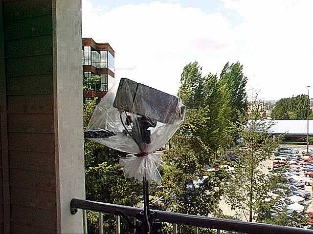
- Transceiver unit mounted atop a tripod on apartment balcony
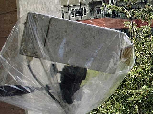
- A closer view of the tripod-mounted unit, showing separate chassis for modulator and receiver circuits
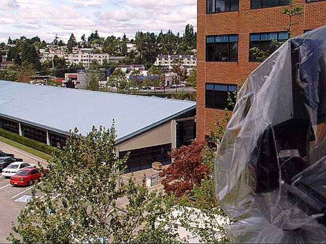
- Signal path, approximately 50 meters. Remote unit is located inside office by wooden crate on sidewalk.
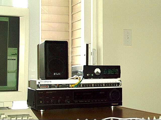
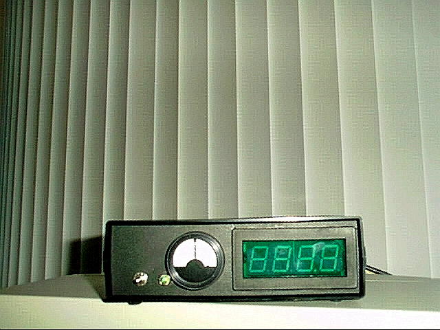
- Link control unit with its associated 10BaseT hub
- A closer view of the link control unit, showing signal-strength and tuning indicators
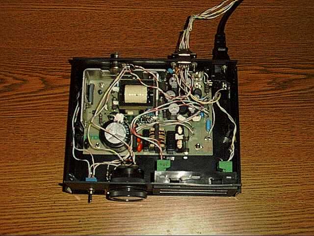
- Inside the link control unit, showing power supply and meter wiring
- Inside the transceiver unit, with subassembly covers in place
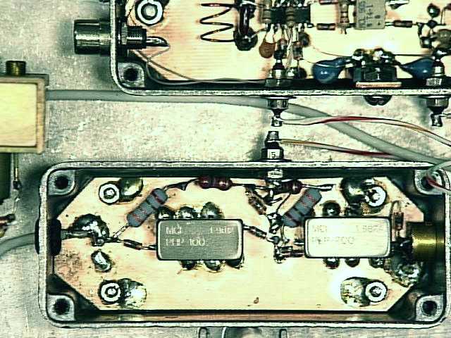
- Inside the IF amplifier subassembly, revealing MAR-6 MMICs and filters
- Inside the MC13155-based FSK demodulator subassembly
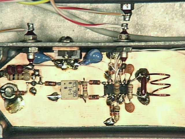
- A closer view of the MC13155 and its associated components
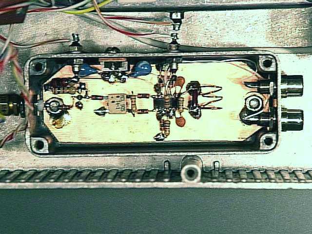
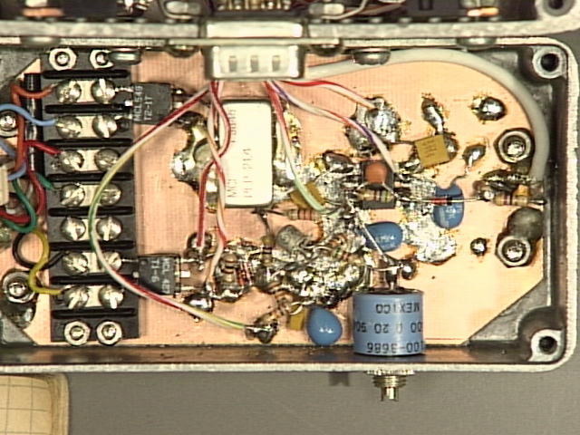
- Inside the Ethernet AUI interface and Gunn varactor modulator subchassis
Schematics
- Ethernet signal as transmitted from AUI Tx port, before filtering and amplification
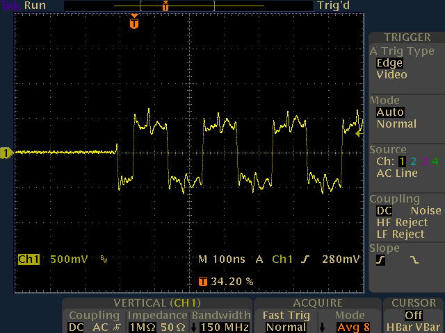
- Amplified and filtered Ethernet signal as applied to Gunnplexer varactor diode
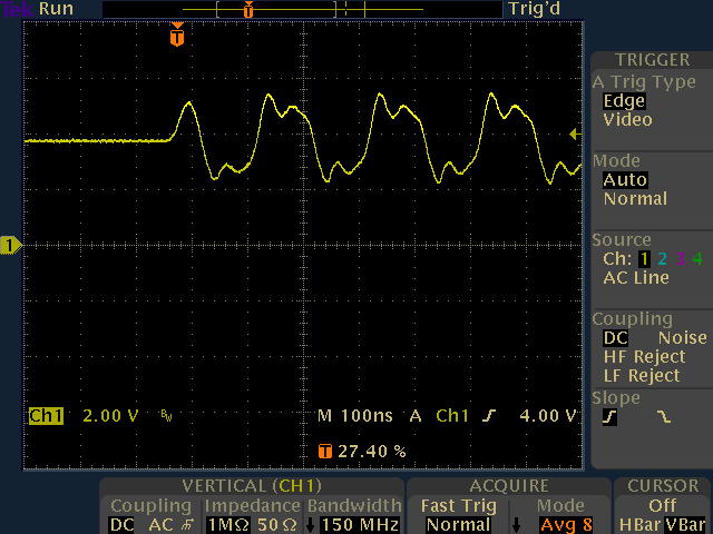
- Received Ethernet signal as delivered to AUI Rx port, after demodulation and filtering
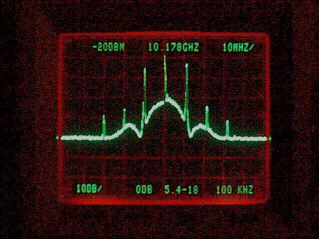
- Spectrum analysis of 10.178 GHz output from Gunnplexer, modulated by 10-Mbit/s Ethernet traffic
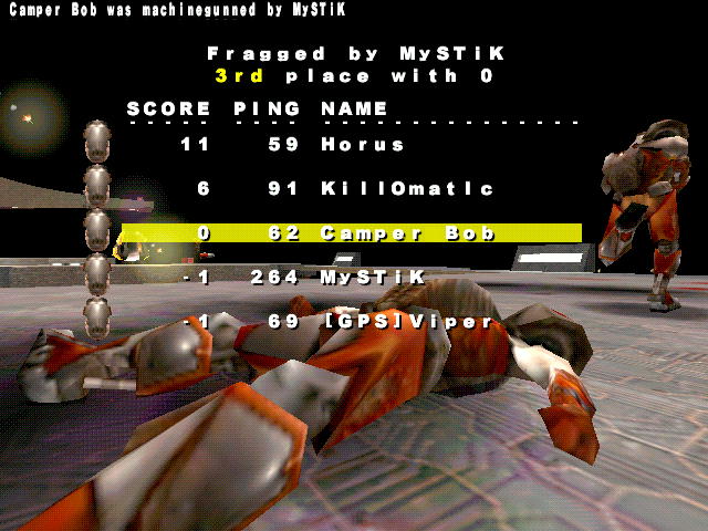
- Qualitative indication of excessive packet loss in early prototype
PC Boards
- PC board design (untested, courtesy of Luis Yanes EB7GWL -- all comments regarding these boards should be directed to Luis)
Copyright © 1999 John Miles. All rights reserved.