By Brian Oblivion
Equipment Required:
-------------------
Dremel or equivelant rotory tool with gouging bit
Tamper bits, (star with center hole)
Small metal file
Soldering iron (A weller will do the trick)
Vise or some sort of third hand
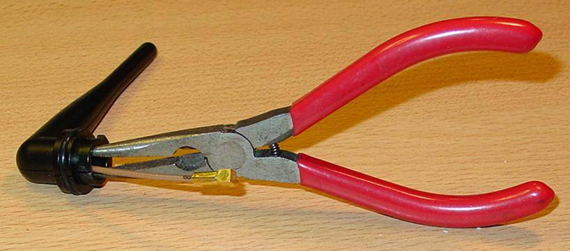
Small needle nose pliers
A pair of fine dykes
A fine dental pic or a straight pin
X-acto knife
Safety Glasses
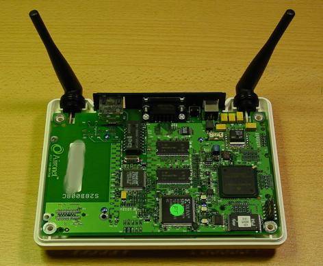
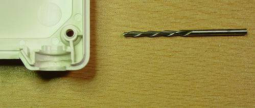
Picture of the Players. Not pictured: Tamper bits, small metal file.
Materials:
----------
Modification:
-------------
1. First thing to do is disconnect all cabling, and turn the unit over to gain access to the four tamper bit screws on the bottom of the unit. Remove the screws.
2. Flip the unit over, and remove the top cover. Unit should now look like this.
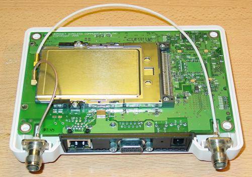
3. Remove the two antenna's from the plastic chassis carefully, and then remove the board, setting it in from of you with the PCMCIA card facing you. Disconnect the antenna pigtails from the card, and put the main board aside.
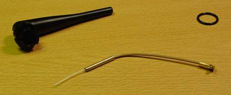
4. Take one antenna, and remove the rubber ring. You will notice that the antenna is hollow and made up of two halves. Close your needlenose pliers and insert into the hole. The idea here is to seperate the two halfs by opening the needlenose pliers seperating the two halves. You don't need to seperate completely, just enough to remove the coax and the brass tubing. The result should look like this.
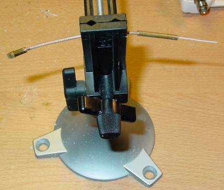
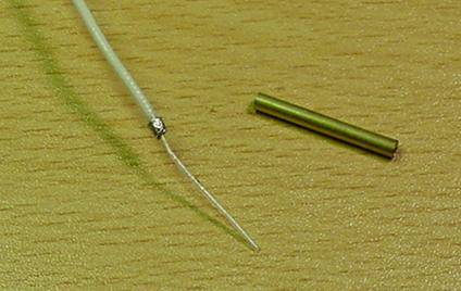
5. Now we remove the brass tubing. Arrange the coax like so in a vise. Apply heat to the end of the tube where the brass is soldered to the braid, but also heat the rest of the tube slightly. Then pull the coax through the tubing slowly while applying heat to the tube. Eventually, it will slide right through. I'm sure there are other ways to do this.. use this method as a guide. You should end up with something like this. Perfrom this on the remaining coax as well. Set aside until next step is complete.
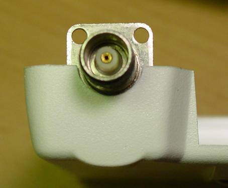
6. It is important to do these steps in order, unless you have extra bulknead connectors to use as fitting samples. It is much easier to check fit of modifications with a connector without the pigtail attached. Now we will retrofit the top chassis to accomodate the RF connectors. When looking at the chassis where the old antenna's sat, there are two plastic slots. The first slot has two plastic posts in it that need to be cut town slighly to accomodate the bulkhead connector. Cut them down with dykes and remove with needlenose pliers until the installed bulkhead appears like this. Repeat to the other side.
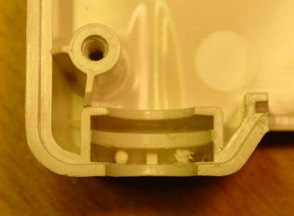
7. Next we perform a similar operation to the bottom half of the chassis. A plastic gnawing bit is used to chew into the plactic area to accomodate the new bulkhead connector. You will find that the plastic is rounded at the bottom of the slot, and that excess plastic should be removed with the bit down to the existing bottom of the slot. Depending on your connector, you should not need to route deeper. Use the slowest speed setting on the dremel, otherwise you liquify the plastic and make a mess and produce a nasty stench. Check fit often. A completed chassis and the proper bit is illustrated here. Repeat to other side.
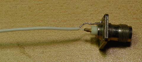
8. Now we attach the coax to the bulkhead connectors. On the TNC connector, there was no explicit way to solder the ground braid to the connector and requried additional preparation. In an area above the plastic insulator, make some groves with the metal file inorder to create an irregular surface for solder to adhere to. Create a solder blob on the irregular region. Solder then signal conductor to the center conductor of the bulkhead connector, make sure you left enough braid to reach the solder blob. Tinning the ground braid will provide extra rigidity needed to ensure that the ground braid and the signal conductor do not touch. Once the signal conductor is secured, solder the braid to the blob. The pigtail should now look like this. Perform the same to the other connector and pigtail assembly. Repeat to the other connector.
Re-Assembly:
------------
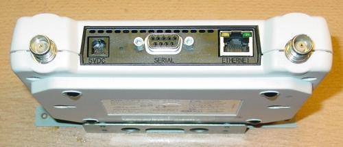
9. Connect the pigtails to the PCMCIA card. The short lead should go to the RF connector closest to the rear access pannel. After connected, place the circuit board into the _TOP_ chassis shell. Then arrange cabling as so. Then carefully put on the bottom chassis. Make sure you don't crimp the long pigtail, take care to start with the front of the chassis first, tucking the long pigtail up into the bottom chassis while lowering the rest of the way down. The reassembled unit should look like this. You may want to replace the screws with non-tamper screws at this point.
Note: These units can support diversity. Left/Right antenna diverstity designations in the firmware configuration menus remain valid as longa s you attack the short pigtail into the connector closest to the rear access pannel. Enjoy