A 2.4Ghz Vertical Collinear
Antenna for 802.11 Applications
By Brian Oblivion and
Capt.Kaboom
You have seen them in catalogs for $150 to $250. Now you can build one for a fraction of the cost at the expense of some time. Construction time can take as little as a few days up to a few weeks, depending on your drive and resourcefulness. Proper acquisition of materials and the tools at your disposal will speed up the construction time. We will go over some theory, tools and materials required, construction steps for the feeble minded, installation tips, and our actual measured results. Construction of an assembly jig will also be covered for those that wish to mass produce a few of these for your community users. Everyone will need at lease one of these units for the multipoint location. Also for those who desire to provide access to a geographic location outside of their immediate locality.
The collinear antenna was historically used by repeater sites, stacking various 1/2 wave dipole elements on top of each other for increased gain connected by some equipment to correct for phase error between the elements of the array. The higher in frequency the better in gain you can achieve in a relatively small assembly. The eight (8) element array we build here will yield 6dBi gain in a radome of less than a meter.
There are 3 main sections to this antenna. Starting from bottom to top of the antenna, they are the RF connector/decoupler section, the elemental array section, and the quarter-wave whip section at the top of the unit.
Components:

	2 meters LMR-400
	2 12" length of 5/16 K&S brass tubing
	1 12" length of 11/32 K&S brass tubing
	1 block of wood of at least (3.52ft) 1m long
	4 1" x 2" scrap wood blocks (or approximates)
	1 1/64th (2mm) thick piece of scrap metal
	1 brass toilet overflow tube ( EXACT DIMENSIONS NEEDED)
	1 US Quarter (or brass disk of equivelent measurements)
	solder (non-acid core plumbing solder)
	flux paste

Tools:

	Required:
	---------
	utility knife
	hacksaw
	High-wattage soldering gun (>260Watt)
	metal ruler (Metric/english)
	metal sandpaper
	metal file(s)

	Would make life MUCH easier:
	----------------------------
	hand-held pipe cutter
	rotary coax cutter
	vise(small)
	micrometer (optional)
	Dremel tool with metal grinding/cutting heads or metal grinder
First determine how much gain you would like the antenna to have. This will detemine how many elements you will need to construct. Choose from the following table:
		Gain		Number of	Length of
		in dB		elements	Antenna (cm)
		--------------------------------------------
		3.5		4		32
		6		8		56
		9		18		116
		10		21		134
For our initial experimentation we decided to build the 8 element 6dB gain antenna.
We chose LMR-400 as it was lying on the floor the night we decided to construct the antenna. LMR-400 coax has a velocity factor of %85, mostly due to it's semi-rigidness and foam dialectric. LMR-200 would be the ideal choice, as it has a smaller diameter dialectric, thus requiring a smaller diameter brass tubing. This makes sense, as the max ERP out for 802.11 is under 1W.
The antenna is designed to optimally operate at the center of the 802.11 2.4GHz band. The center of the band is determined by the following:
	802.11 frequency range:  2.4000GHz to 2.4835


			low_freq - high_freq
	center freq =  ------------------------
				   2


			2.4000 - 2.4835
	center freq =  ------------------------
				  2


	center freq =  2.441GHz
The center operating frequency is then used in the following formula to determine the length of the individual antenna segments:
				(  c  /  Fc  )
	segment length  =  ------------------------ x Vo
				     2

	Where:   c = speed of light in meters
		 fc = center freq.
		 Vo = velocity of coax
In our example:
	 c = 300000
	fc = 2441000000
	Vo = .85

				 ( 300000 / 2441000000 )
	segment length = -------------------------------------- x .85
					     2

	segment length = 52.2 mm
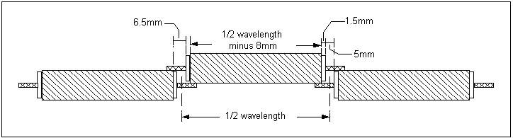
NOTE: This is the length of the antenna segments. The actual brass elements are 8mm shorter than this number, to account for the antenna segment spacing. (See diagram below).
Figure 1. Antenna segment measurements.
The schematic of the electrical components of the antenna is displayed in Figure 2. Note: this schematic is for an eight element collinear array. The 1/2 wavelength and 1/4 wavelength measurements calculated above are to be applied to the various elements in this schematic.
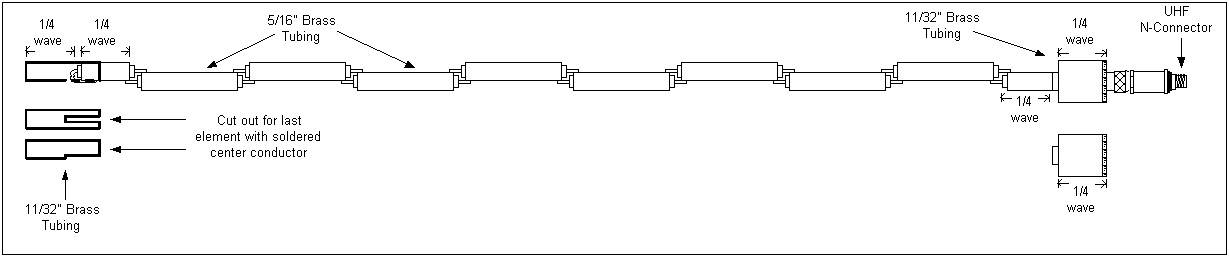
Figure 2. Electrical schematic of the collinear array.
We found that it was easier to cut coax and brass in batches, as you don't have to constantly adjust the micrometer.
Coax Preparation:
Coax length should be calculated in the following way:
coax length = 1/2 wavelength + 15mm
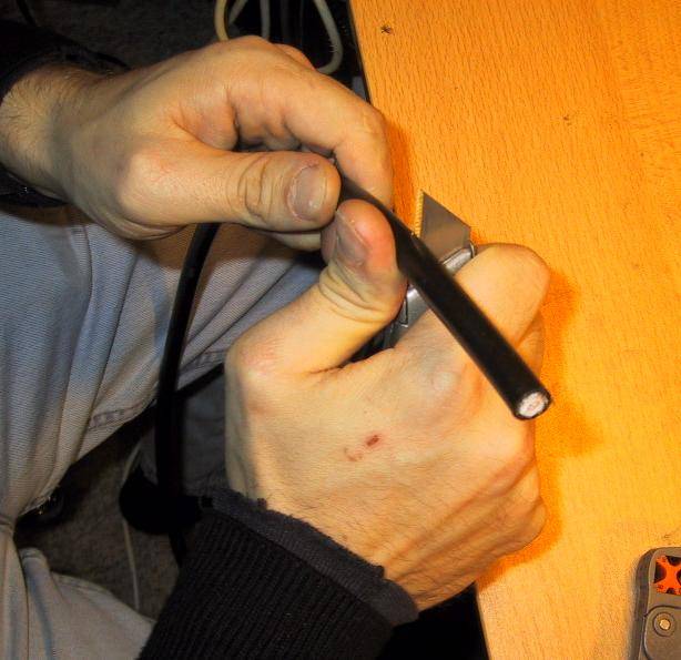
For coax: If you are not using a micrometer, but have access to a vise, mark the proper length (67.2mm) of the coax on the vise with a piece of tape. Align the "cut" end of the coax with the measurement indicated by the tape on the vise. The end of the vise is where you make the cut. (see how it's done). It may be easier to mark multiple sections for later cutting in a batch process. Use the coax cutter or a utility knife to cut the marked sections, and cut and strip away the cladding, braid, and the foil.
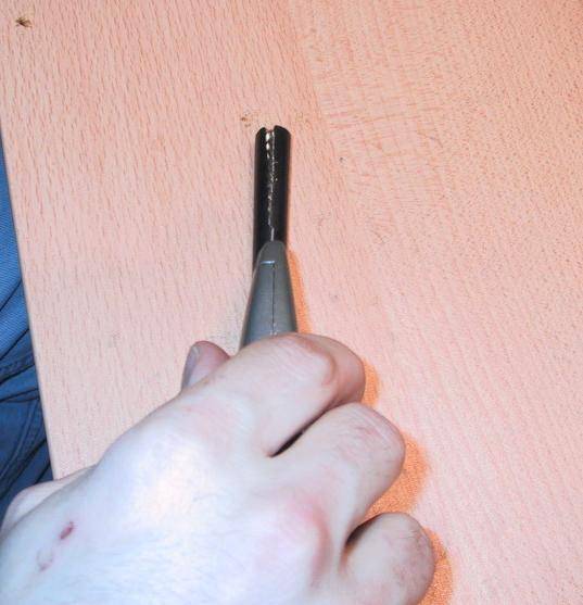
Remove 10mm of cladding from each side the coax segment. Your segment should now look like this. Set aside and prepare the rest of the segments.
Don't forget that the final element of the array is a 1/4 wave element. Cut a segment of coax to fit the 1/4 wave element as well.
Brass Tubing Preperation:
Mark off first 44.2mm segment of the 5/16" brass tubing. Using a circular pipe cutter, set the wheel of the cutter on the side of the mark to make the element a bit longer than the 44.2mm measurement. Cut the brass by moving the cutter in a circular motion around the brass tubing, slightly tightening the wheel with every three or four revolutions. Repeat until all uncut 5/16" brass tubing is exhausted.
Again, don't forget about the final 1/4 wave element! Cut a length of brass accordingly.
Element assembly:
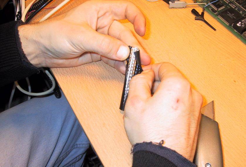
Pair up each of the brass tubing and coax segments. The 5/16" brass tubing fits snuggly over the LMR-400 foam dialetric. Slip a brass element over each coax segment. Slowly twist the brass tubing as you pass it over the dialectric, until it is in place with an equal amount of exposed dialectric on each side of the tubing, like so.
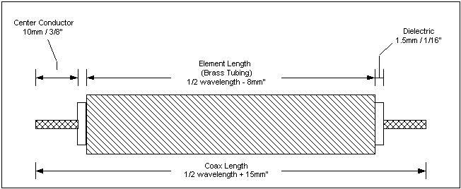
Figure X: Diagram of completed element assembly.
If you think you have the dexterity to solder the elements without the use of a jig, or you plan on only making one or two of these antenna's, then skip the Jig construction and jump ahead directly to the element soldering section.
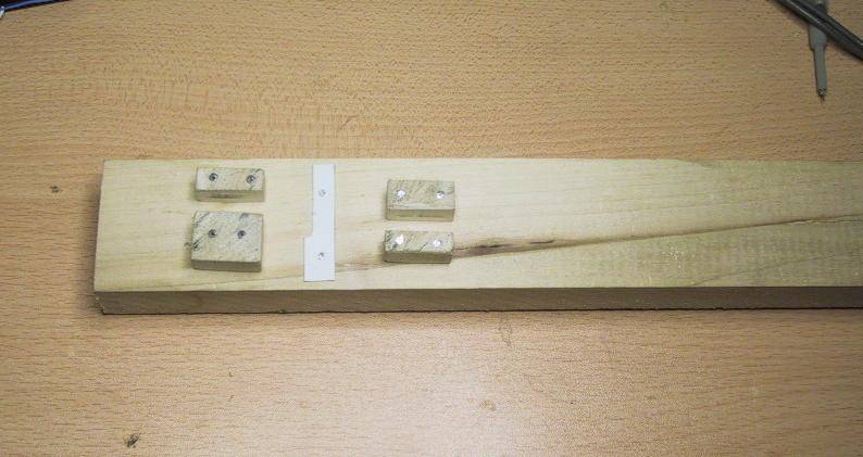
Jig Construction:
To facilitate the rapid construction of multiple antenna's, one should build a jig to assist in the construction. Even when not building multiples, the jig really helps when trying to solder the individual elements together.
Our jig was constructed out of 5ft long 1x2 inch scrap pine wood. a section of the wood was cut to make the four guiding posts used to "hold" the antenna elements in place when soldering together. You will need 10 nails and some scrap metal approx 1/16th thick (same thickness of the brass tubing). Metal PC slot fillers work well, and can be filed down to the proper width. Please refer to Figure 2 and 3 while reading the assembly instructions for visual assistance.
      Step 1: Obtain a 5 foot long 1x2 inch scrap pine wood, 10 finishing
	      nails and 1 PC expansion card slot filler.

      Step 2: Cut a 1 inch section off of the end of the 1x2 board,
              resulting in a 1x1x2 piece of wood.

      Step 3: Cut the 1x1x2 wood into 4 seperate equal pieces.

      Step 4: Drill two holes into each of the 4 wood pieces to
	      accomodate the finishing nails.  Make sure the hole you
              drill is not too large, as we only want to avoid splitting
              the wood when driving in the nails.

      Step 5: Cut away the excess metal from the PC expansion slot
              filler, leaving a two inch long piece of metal.  File away
              one side (or a little of both) to 8mm, and drill two holes
              into the metal to accommodate two finishing nails.  These
              nails will be used to attach the metal to the large piece
              of wood.

      Step 6: Attach the piece of metal 3 1/4 inches from one end of the
              large piece of wood.

      Step 7: Arrange two of the antenna elements in the jig. Use this as
              a guide for where to attach the wood blocks to the large
              piece of wood.

      That's it!
Element soldering:
Element soldering is pretty straight forward. Don't dink around with little 8 US dollar soldering irons for this. You need a high-wattage soldering gun for this job. Spend the $30, it is a worthy investment, and purchase the proper tool for the job. If you built the jig, follow the instructions in Step 7 of the proceeding section. See how easy it is to do it in the jig? If not, then you'll be performing a balancing act, and I hope you have a steady hand.
When soldering the final element(1/4 wave element), remember that the center conductor is bent over and soldered to it's own brass tubing. When completed, it should look like this and this.
Note: Be careful when applying the heat to the brass elements. It doesn't take much time to generate enough heat to begin to melt the foam dialectric.
Solder all the elements at this point before proceeding to the next section. This is what your element array should look like.
Quarter Wave Whip Assembly:
The 1/4 wave whip assembly slides over the end of the last element of the antenna. It See Figure 4 for exact measurements. Because the center conductor of the last element is soldered to the elements brass tubing, the top of the bend of the center conductor will be an arbitrary length unique to each antenna. The important thing here is for the top of the whip to be 1/4 wave in length from the end of the foam dialectric of the last element. Line up the 1/4 wave next to the last element and determine the length the notch will need to be.

Figure 4: Quarter Wave Whip Measurements and position
Use a dremel tool to cut out the notch to accomodate the soldered center conductor of the last element. If you are really slummin', use a hacksaw and file to make the notch. After the notch is cut and burr's are filed away, mount the 1/4 wave whip on the end of the last element.
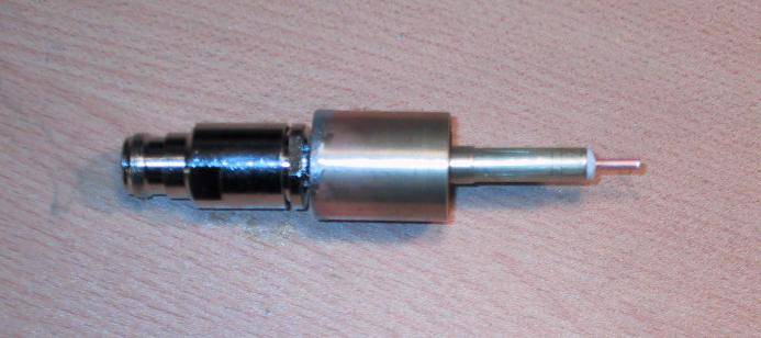
Decoupling and RF Connector Assembly:
The decoupling section is a bit involved, as it requires drilling a hole into a US Quarter, or similarly sized slug, and using a propane torch to solder it to the decoupling brass tubing.
There are two parts to this assembly. First, there is the feedline element, constructed in the same manner as the antenna elements. Second, is the decoupling sleeve, mounted over the feedline element.
The decoupler sleeve is constructed out of 1" brass tubing equal to 1/4 wavelength, a length of 11/32" brass tubing at least 1/4 wavelength, and 1 US Quarter with a center-drilled hole to accomodate the 11/32" brass tubing. A picture of the 1/4 wavelength 1" brass tubing with the 11/32" brass tubing soldered into the center of the US quarter along side. Here is a picture of the fully assembled unit from the top, and a picture from the bottom.
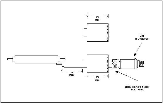
Figure X. Diagram of decoupling sleeve
The feedline is similar in construction to the antenna elements. The difference is the coax is of much longer length than the 5/16" brass tubing. The coax is prepared in a much different fashion since we solder the braid of the coax to the end of the brass tubing 1/4 wavelength up from the end of the N connector. Below this, the cladding remains intact and terminates in the N connector assembly. The brass tubing must be cut so that at least 1/2 wavelength of 5/16 brass tubing is between the end of the decoupler sleeve assembly and the 1st antenna element (see diagram). It must also accomodate the length of the decoupler sleeve assembly plus allowing a length for tuning of the sleeve to the feedling (this is done my sliding the sleeve up and down over the feedline tubing). In our example, the coax was 10.8cm(4 1/4"), and the 5/16" brass tubing was 6.8cm (2 11/16"), in length.
When completed it should look like this and this.
Side Note: We used an RG/8 female N connector because You-Blew-It electronics didn't have a LMR400 female N connector. The point is, it worked.
Tuning and final assembly
Tuning:
Unfortunately, without a spectrum analyzer or high end RF SWR/Power meter one cannot optimally tune the antenna, but one can coursely tune it using the linux wireless tools and two wireless NIC's. By adjusting the decoupling sleeve, you will notice a change in the RSSI reading as you slide the decoupling along the feedline element. Adjust until you reach a peak in the RSSI in the receiver. Only take measurements when not touching the antenna, and always return to a similar position when taking a reading. Your body changes the RF characteristics of the room you are working in. Once the antenna has been properly matched, fix the decoupler in place with a bead of solder and proceed to the next section.
Radome construction:
Outdoor electrical UV resistant conduit was used for the radome. It was cut to the appropriate length to accomodate the entire array, leaving the female N connector hang out the bottom by 1/2 inch. The array is held in place with plumbers epoxy. We used a PVC cap to cover the top, but it could have been sealed with plumbers epoxy as well. Using double sided sticky tape, the array is held in place at 2 locations within the tube.

Figure X: diagram of finished antenna in radome.