Design by clapp@aeonic.com. Address questions appropriately to this fellow.
It has been mentioned to me that 2.4GHz is not really the only frequency used by 802.11b. It is the begining of a band of frequencies on up to 2.4835GHz. As the frequency increases, the wavelength decreases, so to move towards the center of the band you will want to shorten your spacers.
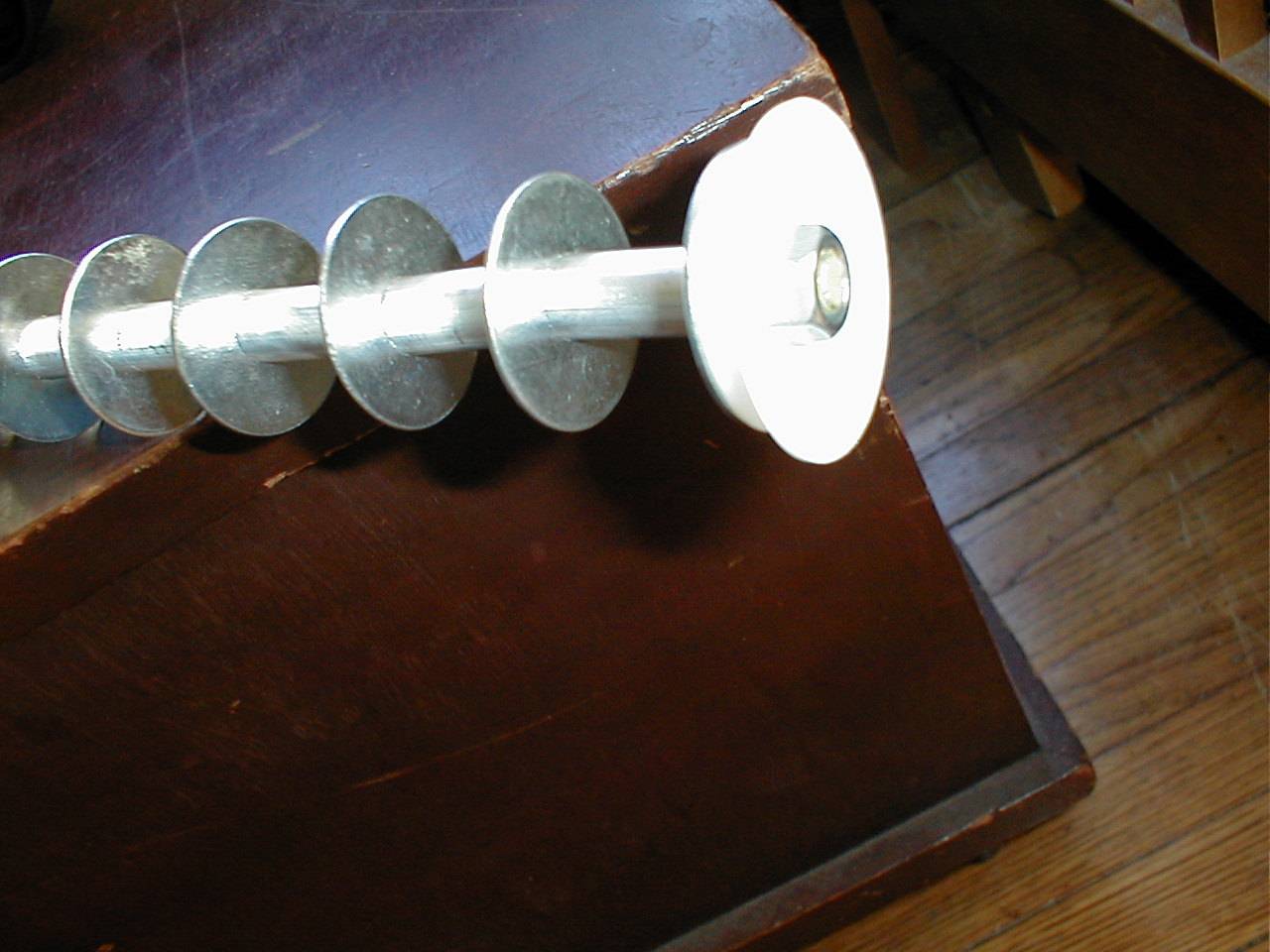
In my spacing (see below) on my antenna, I intentionally errored on the larger rather than smaller side of size. I did this because the hacksaw is fast, but makes less exact, sometimes slanted cuts. I used a file to flatten out the ends and bring the aluminum spacers down to a more precise size/shape. Ideally, when you know what frequency your particular device is, you can build accordingly. Something within 12.0-12.5cm should work out well. This is not rocket-science.
To calculate wavelength, we can start with some very basic math.
The wavelength is the distance that the radio wave
travels during one cycle. One can imagine a sine wave flying
through the air. This picture shows one cycle of a wave.
For our purposes, radio waves travel at the speed of light. That means our rate is about 3.0 x 10^8 meters per second. It's a constant, which means that Distance/Time will always be the same.
Rate * Time = Distance, or C * T = W
Notice how the time and the distance portion of our little equation are related. The time we are concerned about is the time it takes our radio wave to complete one cycle. This time is called the period of the wave. This will typically be measured as some small fraction of a second. Since the measurement of frequency is the number of cycles in 1 second, the frequency multiplied by the period will always be one.
1 = Period (length of time / 1 cycle) * Frequency (cycles / second)
or
T * F = 1

The Frequency of our 802.11b wireless equipment is 2.4 x 10^9 Hz.
(Hz is just short for cycles per second.)

So now we have two equations with two unknowns.  (Sound familiar? Good. :-)

W = 3.0 x 10^8 * T

and

T * 2.4 x 10^9 = 1

We want to solve the first equation for W.

W = 3.0x10^8 * (T)

And substitute the second one solved for T (in parenthesis).

W = 3.0x10^8 * (1/2.4x10^9)

W = 3.0x10^8 * 2.4x10^-9

= 3.0/2.4 * 10^-1 = .125m, which is 1/8 meter, or 12.5cm

(2.4835GHz yeilds 12.0797cm, which rounds nicely to 12.0 for now.)
Now that we know our wavelength, what do we do with it? Well, many folks have many ideas of what to do with it:
Here is what I did with it. My test platform is an Airport with a cigarette-ligher adaptor to plug into my car, and an old laptop with a lucent gold card, each with an antenna that I built as described below. I don't have a working mac, but Mark configured my airport with his mac. The laptop is currently running win2k, and I'm using lucent's software package for measurements. As soon as I get time to build some custom kernels, I hope to be running NetBSD. Then we'll see some extremely nifty things.
| Airport Antenna | Laptop Antenna | Distance | Highest Rate | Ping Times | Signal | Lucent Bars |
| None | None | 30 ft | 11 Mbits | 10 ms | -40 dB | 5 green |
| 36" yagi | 36" yagi | 1000 ft | 11 Mbits - ?% | 10 ms pings | -85 dB | 5 green |
| 18" yagi | 36" yagi | .7 Mile | ? Mbits - ?% | ? ms pings | -89 dB | 4 yellow |
| 36" yagi | 36" yagi | .7 Mile | ? Mbits - ?% | ? ms pings | -93 dB | 4 yellow |
I am currently suspecting that the higher precision I put into making the smaller antenna paid off. :-)
A particularly useful piece of information is that half-wave and quater-wave lengths can be used as well. You will find that the quater-wave is very popular in many antenna designs.
Our quater-wave length is .125 / 4 = .03125 meter. Remember this is the bottom of the frequency band. It's the "longest" end.
I chose to use materials that were most economic and readily available for my construction. If you want to spend money, go buy me a parabolic grid antenna. :-) If you want a fairly good antenna for a fairly reasonable price, go to Home Depot or your local hardware store and buy something like the following materials. I encourage you to try different things. Mine worked, but there are surely better ways to do this.
It is true that the longer your antenna, the more gain you will get.
More gain == good(tm). I've read somewhere (and it may or may not
be the case) that the gain increase levels off rapidly after 6 or 7
wavelengths and it's not important to design beyond that. The 36"
rod is (39.3700 inches per meter) about .9144 meter or a little over
7 wavelengths long. Overkill is a way of life.
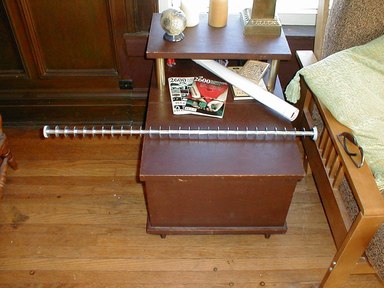
Whole Antenna
For a reflector, you will need to experiment. I've gotten away
with such things as a planters cashew nut can, a chicory coffee can,
a pirouline can, a pringles can, and I'm currently looking at
a old lighting fixture can cause it looks neat.
I used the pringles can for the smaller antenna.
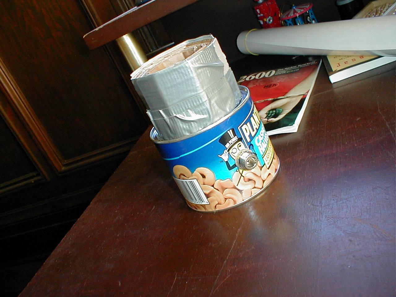
Cashew Can
The basic idea for a reflector is to mount an N connector in the
side of the can near the middle of it's length with some sort of
radial extension from it's center contact. The extension does not
need to touch the 36" rod. You should try adjusting the position
of the reflector relative to the antenna to get the best results.
Several Layers of Cardboard and Duct tape hold the abs pipe in place.
Reflector
Some interesting info from ISAAC on WEP
If anyone has anything to contribute or ideas to share or things to improve the design, please email me. :-) I'll keep this page updated with any new and useful data.
Thanks to Jeme for the use of his cool Olympus digital camera. And to Ricky for hosting the page until his server dies or his connection saturates (whee big pictures). Thanks also to Mark for inspiring the original beta test. Thanks to the gang at Seattle Wireless for the good antenna/airport info and pics. Thanks to Feef (the Mad Beamer, who beams at midnight) for the late night testing on the island. And thankyou great masses for all the feedback and comments.