by
Brian Oblivion
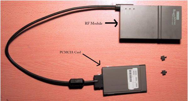
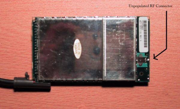
There is an unpopulated socket for an external antenna connector to be attached to the transceiver modules of the legacy wavelan type PCMCIA cards. The procedure of modifying this card follows.Prior to the Lucent Orinioco/Wavelan product line, they produced non-802.11 PCMCIA cards. These units can be identified by the external transceiver dongle. They were made under the Lucent, Cabletron, and Digital names (there may be others but they slip my mind). These cards surface from time to time at flea markets and on ebay, but are becoming much more scarce. There are two flavors of cards, 900Mhz and 2.4Ghz. The cards can be identified by examing the back of the transceiver unit for the FCC ID number.
FCC ID Transceiver Type IMR24PCMCIA 2.4Ghz IMR915PCMCIA 900Mhz There are two screws on the underside of the transceiver unit. Remove these screws and carefully pry the two halfs of the cover apart. You will see the unpopulated antenna footprint at the top of the transceiver PCB.
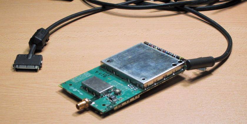
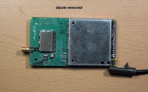
1. locate the dual integrated dipole antennas, desolder and remove. The foam blocks they sit upon just rip off with a little force. Go for it.Depending on your plastic widdling skillz, your finished modification should look like this, and this.2. Obtain a female 5-post(four ground, and center signal conductor) SMC PCB mount RF connector from your favorite RF connector source.
3. You will notice that the posts of the SMC PCB mount connector line up exactly with the ground and signal holes of the PCB, when mounted sideways on the edge of the board. The PCB is to be slid in between two of the ground posts and the signal conductor. The posts should rest on the through-hole solder pads evenly. Allow enough space to run a copper wire through the holes to provide better solderability.
4. The two remaining ground posts that do not sit directly on the PCB should be gingerly bent downward until they rest upon the opposite side of the ground pads.
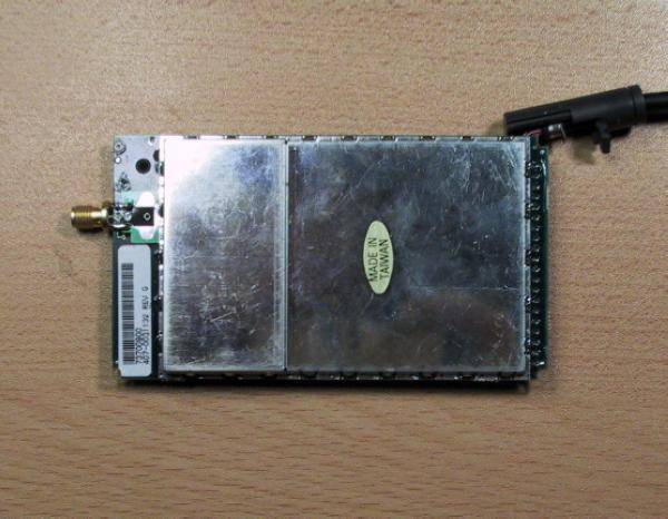
5. Solder all posts of the RF connector to the PCB pads. The result should look something like this. (Sorry about the blur.) Here is a top view and bottom view as well.
6. Cut holes in both top and bottom transceiver plastic housing to accomodate the new SMC connector.
7. Reassemble and enjoy!!!