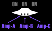
Above is a legend indicating the designation of the amplifiers from left to right. A, B, and C. The ON/OFF indications on top of the craft represent the Amplifiers A, B, and C respectively. Illustrated below are the various combinations of gravity amplifier lensing directions and states of operation and how they influence the movement of the craft.
See also DELTA & OMICRON configurations.
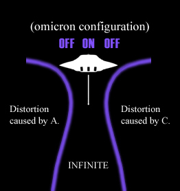
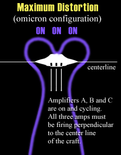
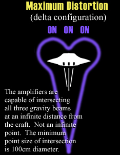
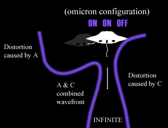
The illustration below left indicates how the craft achieves lateral movement. The depression or distorted wavefront creates an area that the craft simply rolls or falls into. Perpetuating this effect combined with the lift of the single amplifier results in the craft moving lateraly in a constant fall to the left. This accounts for the craft looking very wobbley at low altitudes and speeds when not in a maximum distortion state. Compare this to the illustration to the right which indicates a simple hover mode. The two illustrations at the bottom compare the maximum distortion state for both the Delta and Omicron configurations. |
 |
|
| |
|