SHOOTOUT!
Hear an actual head-to-head demonstration (stored as an MPEG layer 3 file [3.73MB]) of an actual
working air chain consistiing of these circuits, versus several FM stations
around the dial. I think you won't have any trouble telling the differences between the
flagship radio station and the rest of the crowd, despite the fact that these
circuits, designed and built in 1982, are being compared against state-of-the-art 1998
radio stations. Also note that despite the fact that the receiver is literally right under
the transmitting antenna, the 2nd adjacent stations receive no interference whatsoever
from the test station. Also note that according to my modulation analyzer, this test
station one of only 3 stations on the dial that is within 100% deviation limits. The
majority of the stations are running 104-105%, without subcarriers. Now that's modulation
control! :-)
 |
 |
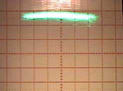
| The local 50kW vectorscope display. Note
fuzzy, non-definate deviation boundaries at left and right edges. 25Khz/div 120dBu |
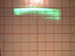
My single-band limiter vectorscope
display. Note sharply-defined deviation boundaries at left and right edges. 25Khz/div
120dBu |
Recently, I discovered what a
"piece of cake" American recordings are as far as technical challenge to
broadcast audio. They seem to be optimized for good on air sound. My airchain sounds even
more impressive with the selections from Michael Jackson's BAD album. Notice the
brighter, crisper highs, louder midrange and deeper, woofer-shaking bass in the flagship
station's audio. Click the right hand demo sample for a familiar program content to
compare with. Note that the file extention is MPEG, but is really and MP3. The ISP won't
accept MP3 uploads, so the alternate name was a necessary trick.
|