 |
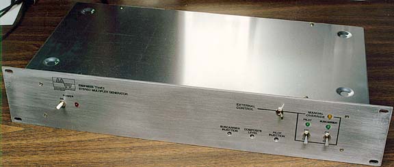
| The completed Stereo Generator, housed in a BUD chassis with 2RU front panel. |
Contained herein are schematics and photos of a Stereo Generator which I recently completed construction of. This is a true broadcast-quality generator, offering superb channel separation, audio low pass filtering and remote control capabilities. Particular attention was paid to the filtering of the pilot and subcarrier. Harmonic distortion is so low that a sweep from 20cps to 16,000cps revealed no audible beat hetrodynes at the critical frequencies of 9500cps and 13500cps, or any other frequency within the operating range. This test was performed both with one channel driven and with both channels driven. This absence of beat hetrodynes results in this generator's unique CD-like sound quality and sparkling treble clarity. (SAMPLE AUDIO, MP3, 671Kbytes, recorded off the air on a high quality tuner.)
|
| The completed Stereo Generator, housed in a BUD chassis with 2RU front panel. |
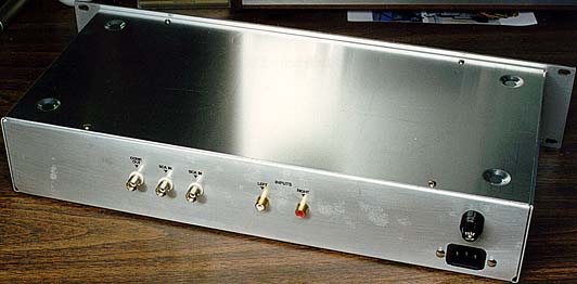 |
| Rear apron view of the Stereo Generator. |
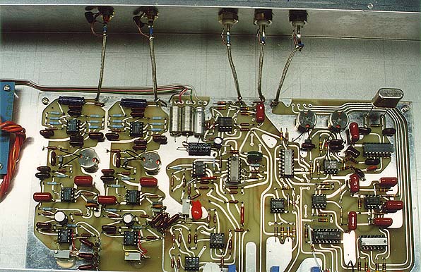 |
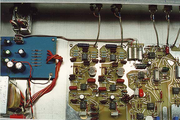
| This is the main PCB for the stereo generator. The master timebase, using a Pierce crystal oscillator in conjunction with a 4066 IC, is at upper right, along with the filtering circuits. Audio LPFs are at the left. 4-quadrant multiplier (1496) and associated circuitry is at center, just above the matrix. Lower right contains remote control logic, carrier detectors and switching. |
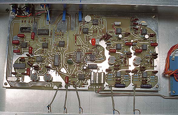 |
| A slightly better view showing the front panel wiring. |
 |
| This view shows the power supply to the left. Power transformer was oriented for minimum magnetic field in the direction of the audio circuits. Power supply PCB uses my exclusive "Two Point" grounding system to isolate center tap ground switcing spikes from voltage regulator output ground. Note use of CorCom EMI filter at upper left. |
This is an excellent stereo generator that will give at least 50DB of channel separation (I've measured over 60dB of separation while monitoring my broadcast on a Sequerra Model 1) and a frequency response from 20-16,500hz (+/- 0.25dB from 16cps - 15,000cps, -3dB point at 16,000 cps), using a unique low pass filter design that's so sharp we were able to extend the upper frequency limit by 1.5Khz. Your listeners will notice the difference, with clearer, more open treble and lower distortion.
NOTE: These images were scanned directly from the original photo
etch master film at 300DPI.
COMPONENT NOTE: The Siliconix DG201 Analog Switch is available from Temic Semiconductors. Data sheet available in Adobe Acrobat PDF format on their web site at: DG201B
Download PCB Layout for Component Side of MUX board
Download PCB Layout for Solder Side of MUX board
| CUSTOM CRYSTAL may be obtained from: JAN Crystal Tel: 800-526-9825; Fax: 941-936-3750 |
| THE PROOF IS IN THE PILOT | ||
| Recently, there has been some debate over the quality of pilot tones and the necessity for a spectrally-pure pilot tone. Controlled laboratory testing has demonstrated that the purity of the pilot has a direct influence on the quality of treble audio, particularly bells and chimes with high pitched, pure sounds. | 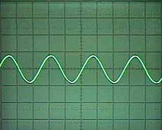 |
Here is the output of my second generation stereo generator, whose schematic is above on this page. While the oscilloscope can't show it, all harmonic output is filtered and attenuated to >-80dB below pilot fundamental. This has resulted in excellent 60dB stereo separation all the way to 15KHz. |