FM Transmitting
Antenna Page
The following design is being offered in the public domain for
the benefit of those who wish to do their part in the defense of
freedom, justice and the American way by exercising freedom of
the airwaves.This is a very effective antenna system, for getting
the most out of a small transmitter.
FCC WARNING - Many small
transmitters are capable of exceeding Part 15 of the Rules for
low-power broadcasting when connected to this antenna. Please be
aware that it is possible to use this equipment in a manner that
can place you in violation of federal laws. Before you construct
this antenna, you should familiarize yourself with FCC rules with
regard to radio transmission devices, and be aware of the
boundary between legal operation and illegal, unauthorized
operation. It is up to you to assume legal responsibility for
your actions as you use this equipment.
The antenna system about to be described here is a superset of
the classic "J-Pole" design. The basic J-Pole has a
gain comparable to a dipole - about 2.5DBi. The author wanted
something better, so he investigated several types of antennas.
An omnidirectional pattern was desired. Also, minimal skyward
radiation and minimal radiation back to the building on which the
antenna is installed was a requirement. A vertical design
addressed these concerns. The radiation pattern of this antenna
approximates that of a doughnut lying on its side. Maximal
coverage of populated areas is achieved in this way. The gain of
the antenna described herein is about 8.8DBi. Switching to this
antenna has much the same effect as tripling or quadrupling
transmitter power.
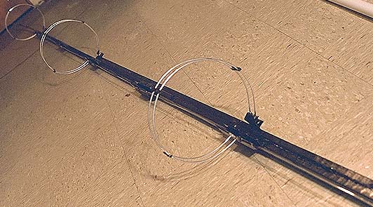
The 4-bay J-Pole antenna, nearing completion, just after the
wooden mast received a coat of black epoxy paint. Note circular
phasing stubs, which are non-radiating 1/2-wave transmission
lines. The entire radiating element set is formed of one
continuous piece of 10 AWG aluminum wire, measured and bent at
the precise 1/2-wave intervals. Light weight was a major
engineering requirement for this project, so laminated wooden
strips and aluminum wire were chosen as the main materials. This
antenna's support is tapered thinner at the top end. The design
was successful, since the bottom of the antenna may be easily
lifted and the antenna held out horizontally in front of the
person, without bending or snapping in half. Such a strength to
weight ratio makes it possible for a single man to raise this 30
foot antenna, nailed to the end of a 12 foot 2x3 without
assistance. The entire antenna, by itself, weighs just about 8
pounds. Earlier designs became too heavy after more than 2 bays
were included.
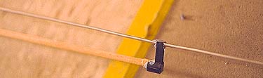
![matchxfr.jpg - Matching Tfr]()
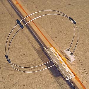
Detail of the matching transformer assembly and phasing stub
assembly. The matching system is of the classic "J"
variety, functioning much like an autotransformer voltage step-up
at R.F. frequencies. The phasing stub at right is a half-wave
delay line -- essentially, a half-wave antenna, folded back on
itself so it does not radiate. (See "Phasing Stub Operating
Principles" later in this document.) The spacers for the
phasing stubs are 1-1/4" cut pieces of computer card cage
guides. Snap-in holes to snugly wrap around the 10 AWG aluminum
wire were formed in the plastic by melting through with the tip
of a hot soldering iron.
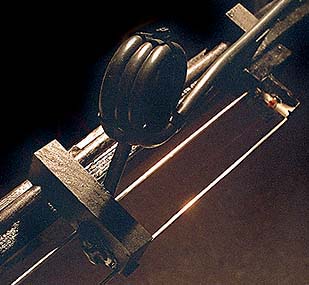
Detail of a choke balun, or current balun. Unbalanced antenna
currents naturally flow back on the outside of coax feeder lines;
this choke presents a high resistance to those currents,
effectively blocking antenna currents from carrying back down the
outside of the feeder and causing various potential problems with
SWR, loss of power at the antenna, etc. Two of these baluns are
placed 1/2 wave apart for very effective suppression. Note the
wooden slider assembly made from furniture-grade Ash wood and a
hardwood dowel. The photo at right shows the sandwiched PC boards
that form the sliding contacts which connect the feeder line.
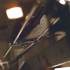
A detail shot of the top section radiator and how it's supported
by a pair of lightweight wooden dowels.


Updated Photos
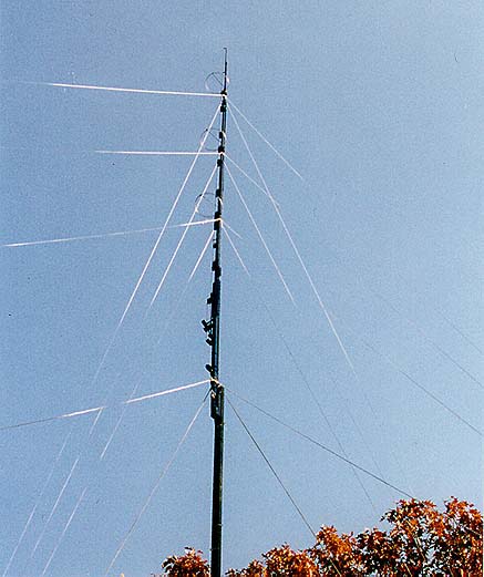
Two views of the finished installation on a third-story
rooftop. Due to the severe battering hurricanes, the number of
guy wires was increased to 16. The antenna height was increased
by 13-1/2 feet. The active radiating element area is
approximately 23 feet long (between the horizontal phasing
"rings," which lends a little perspective to how
massive this antenna is). The RG-11 feeder coax has low radiation
in this installation and antenna performance is several orders of
magnitude better than prior 2- and 3-bay J-Poles the author
previously constructed from copper pipe. Note the two choke
baluns just above the first guy cables. The top of this antenna
is roughly 82 feet above ground on a 1253' AMSL elevation.
A carefully-constructed antenna can make all the difference
between good coverage and enjoyable listening for your audience,
and no listeners at all. The antenna project described here has
been tested and has shown that a dramatic increase in signal
strength can be obtained over more conventional antennas, just by
increasing antenna gain. I leave these designs in the public
domain for those hearty technical people who wish to build a
better station than what they could get by buying a kit. Use them
to further the goal of free radio broadcasting and the American
way!