 |
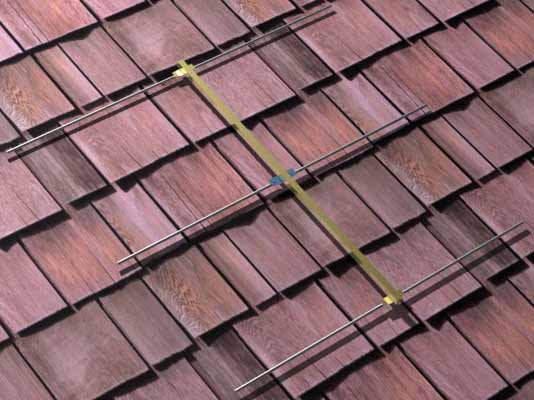
The completed
Yagi antenna, just before attachment of coax and coax
balun. Top of picture is the reflector, driven element is the middle and director is closest at bottom. |
Very often, the necessity for strong coverage in a narrow zone calls for the characteristics of a beam or "Yagi" antenna. Many microbroadcaters take the simple approach and use an off-the-shelf antenna, such as the ever-popular 6-element beam from radio Shack. These can work quite well, but one must bear in mind that such antennas are designed for a 20% bandwidth-to-frequency ratio and employ a greater number of elements and trade off some gain, not to mention lightweightness and simplicity, to do this. A better approach is available to the enterprising microbroadcaster who enjoys getting into the nitty-gritty of antenna construction. And so I present my 3-element Yagi design.
FCC WARNING - Many small transmitters are capable of exceeding Part 15 of the Rules for low-power broadcasting when connected to this antenna. Please be aware that it is possible to use this equipment in a manner that can place you in violation of federal laws. Before you construct this antenna, you should familiarize yourself with FCC rules with regard to radio transmission devices, and be aware of the boundry between legal operation and illegal, unauthorized operation. It is up to you to assume legal responsibility for your actions as you use this equipment.
Obviously, as a broadcast station, your outfit is not concerned with receiving frequencies over a 20Mhz bandwidth. You transmit on just ONE frequency. To this end, the optimized design focuses on resonating all driven and parasitic elements at the carrier frequency. This design allows a slightly higher gain to be achieved with half the number of elements. The Yagi featured here offers just a tad over 8dBi gain with just 3 elements, in a package with a boom length of just 56 inches (shorter, if you operate on the middle or upper end of the band). Additionally, an antenna, designed for your frequency, will present a lower SWR than a standard broadband receiving antenna.
|
The completed
Yagi antenna, just before attachment of coax and coax
balun. Top of picture is the reflector, driven element is the middle and director is closest at bottom. |
While entertaining alternate ideas for a replacement antenna system, I reconsidered the Yagi. And I happened to have a 34-year-old TV antenna that was a veteran of the great tornado of 1964, and was presently providing a nifty obstacle course for the various ground vegetation growing in my yard. I discovered many salvageable parts on this behemoth of a late 1950s TV antenna. Armed with a 1/8" drill and a hack saw, I drilled out all the rivets holding elements and sections together. I cut bent sections that were beyond repair off of the salavaged elements. The boom length needed was much shorter than the original --about half the length --so I cut that to the desired calculated length of 56".
While there is no fixed, hard rule that dictates a particular element spacing, I chose 2/10ths of a wavelength between elements as that spacing was in the midrange for optimum gain. Wide bandwidth was not necessary, so I designed for maximum gain with minimum SWR at the operating frequency. Element dimensions, as a function of wavelength, are given in the table below:
| Reflector length =
501/F(MHz) Driven element length = 473/F(MHz) Director length = 445/F(MHz) |
The completed antenna presented an SWR of less than 1.2:1 at the operating frequency, and the impedance presented to the MFJ-259 test set was in the neighborhood of 70 ohms. Because of this, no 4:1 matching balun is needed, as with the commercial receiving antennas. I did insert a simple choke balun, by simply winding three turns of the coax at a 3" diameter, as a measure to isolate antenna currents from flowing back on the feedline shield.
Using recycled parts from the original TV antenna, the Yagi was assembled with the aid of 8-32 x 1-3/4" screw hardware. I measured off the locations for the elements and drilled 1/8" holes at those locations. being that the the rivets were drilled out from the original brackets, it was easy to mount them in the new locations. The elements themselves, several of which were left riveted to their brackets because their condition was good enough to warrant reuse, and the fact that they were long enough to meet the dimension requirements, could be reused in some instances without drilling out the swivel rivets on the brackets. Others were deemed too damaged, or too short and those were drilled out and the brackets reused with 7/8" 6-32 screws with locknuts, to afix new 1/2" aluminum tubing which was cut to spec. A hacksaw was handy for all cutting operations and worked well for the job. Mounting the Yagi to a 1-1/4" aluminum pole is accomplished by drilling two 5/16" holes through the side of the boom at spacings which match those of the Radio Shack "U-clamp" antenna mounting bracket. A good place to place this bracket is equally between the reflector and driven element. Make sure all mechanical mounting is tight, so as to prevent the antenna from spinning around like a wind vane.
For the driven element bracket, the fiberglass/plastic bracket was reused. However, due to the nature of the original threaded terminals being part of a long pop rivet that had been drilled out, it was necessary to replace these terminals with 2" long 10-32 screws, and use some 1/2" stainless steel bushings which I had scrounged out of my junk box, as spacers and mounting plates for terminals. By using two nuts on each stud, one locks in the stud to the bracket, and the other is used for connections to the feedline. Some flat washers between the nuts complete the terminal assembly.
This Yagi provides a 60-degree azimuth spread for the 3dB down points in the E-plane (electric field) and a 120-degree spread in the H-plane (magnetic field). Performance is as good or slightly better than the Radio Shack 6-element beam, despite an uneven playing field which gave the 6-element antenna a 20' height advantage and RG-11 coax versus some old scrap bin RG-6 TV coax for the Yagi under test. I hope to document the performance again using RG-11 at the full height, when I switch antennas.
This antenna can be used singularly, or in an array of antennas, as this author intends. When stacking two antennas, a simple matching transformer is needed, to transform the impedance of two parallel-connected Yagis to a feedline (in my case, 70-ohm RG-11). Since my Yagis are each 70 ohms, the two in parallel yield half that impedance. A quarter-wave linear transformer, consisting of a section of RG-8 (50-ohm) coax was the perfect match to create the desired surge impedance to the feedline. Since the velocity factor of this RG-8 is 0.8, I simply use the formula (246/frequency) x 0.8 to determine the needed length of RG-8. I verified the accuracy of the cut with the impedance meter and found it to be "dead nuts" accurate and in need of no trimming. This got connected to the junction of the two antenna feedlines that come down from the Yagis (which are of identical length). The other side of the "transformer" feeds the coax feedline to the transmitter. If you use an array of four Yagis, connect them in groups of two, each with their own transformers, to a third transformer, as if connecting two Yagis above. The topography of the connections forms a branch with a hierarchy of 70-ohm tap points which get paralleled with another branch. In this manner it is possible to connect multiple Yagis to form arrays inexpensively.
Stacking two Yagis at 1/2 wavelength spacing, aimed in the same direction offers vertical beam compression and 2.5 dB of additional gain over the one Yagi. Stacking and staggering two Yagis by 60 degrees, offers a 120-degree wide coverage area at the 3dB-down points. While this type of antenna still hits the shack and close-in surrounding areas directly in front of the director element with a disruptively-strong RF field, it also provides one of the strongest signals in the favored direction toward which it is aimed, of any antenna design available. My advice is not to aim this in the direction of populated areas, and for your own safety, mount it as high up as possible, and where possible, aimed away from your studio location. This antenna does have an excellent front-to-back ratio of 35dB, so you can be directly behind it and receive almost no dangerous levels of RF radiation, even with 50 watts feeding it.