|
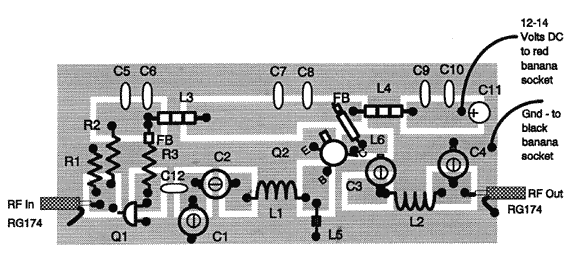
Begin by laying out the parts on the circuit board to get a feel for the situation.
Solder the components to the pads and areas indicated in the layout diagram below.
Keep coil, resistor, capacitor, and inductor leads as short as possible and raised
about 1/16 to 1/8 inches above the surface of the circuit board. The area
surrounding the pads is ground. C1 & C2 are soldered at one end to the ground
area as well as the shield braid on the coax cables. Slip the top hat heat sink
on Q2 for proper heat dissipation.
 With an input level of 10-15mw, tune variable trip capacitors C1-C4 for maximum
power - do not exceed 1 watt. Be sure to have a proper dummy load (50 ohms) or
tuned antenna connected to the output, doing otherwise will likely destroy the
transmitter.

Parts List
| Quantity | Description | Part Number(s) |
| 4 | 10-50 pF variable trimmer capacitor (orange or yellow) | C1, C2, C3, C4 |
| 4 | 0.001 mF capacitor (marked 102) | C5, C7, C9, C12 |
| 3 | -.1 mF capacitor (marked 104) | C6, C8, C10 |
| 1 | 10 uF electrolytic capacitor (observe correct polarity) | C11 |
| 1 | 4 1/2 turns #18 tinned bus wire, 3/8" dia. | L1 |
| 1 | 6 1/2 turns #18 tinned bus wire, 3/8" dia. | L2 |
| 2 | three ferrite beads of #20 bus wire | L3, L4 |
| 1 | 6 turns #26 enamel wire through ferrite bead | L5 |
| 1 | 0.5 uH inductor with ferrite bead on the lead connected to 12 volts | L6 |
| 1 | 2N4401 or MPS918 | Q1 |
| 1 | 2N4427
(note: a 2SC1970 can be substituted for higher power output if proper heat sinking is
observed. this transistor can be ordered as an option with the correct heat sink for
$8 postage and handling included)
| Q2 |
| 1 | 1.5K 1/4 watt resistor | R1 |
| 1 | 20K 1/4 watt resistor | R2 |
| 1 | 300 resistor with ferrite bead on the lead connected to 12 volts | R3 |
| 2 | SO239 socket | |
| 2 | banana plugs (1 each red and black) | |
| 2 | banana sockets (1 each red and black) | |
| 5 | ferrite beads | |
| 4-40 nuts | |
| 4-40 bolts | |
| RG174 coaxial cable | |
| hookup wire | |
| soldering lugs | |
|

