This is a Very-Low Frequency (VLF) converter to increase the frequency response of a radio receiver operating below 500 kHz. This front-end converter uses a stable 10 MHz Local Oscillator (LO) to "upconvert" the 1 - 500 kHz band to 10.001 - 10.500 MHz.
A standard HF receiver (or spectrum analyzer, computer soundcard, etc.) can then be used to further break down and examine the target RF signal(s). For example, the 15.75 kHz horizontal synchronization signal from a standard NTSC video camera would be converted to 10.01575 MHz. At this slightly higher frequency, it's easier to construct narrowband filters or utilize a receiver with a finer tuning frequency "step."
There are numerous VLF converter schematics on the Internet, many of which are much simpler in design. The circuit shown here was designed for high-performance RF test lab or TSCM operations, so some of the parts may be expensive or difficult to track down. The overall concepts can be used for your own design, if necessary.
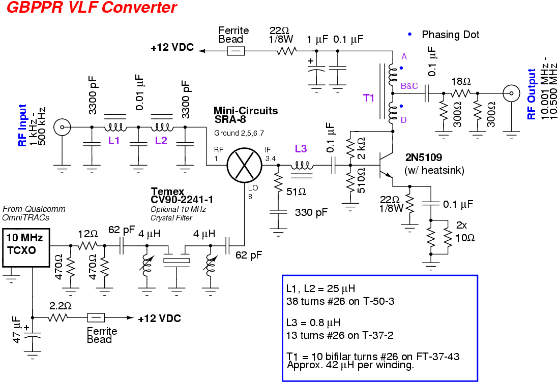
The GBPPR VLF Converter consists of a Mini-Circuits SRA-8 mixer feed via a 5-pole Butterworth 500 kHz low-pass filter on its RF port. The low-pass filter utilizes high-Q silver mica capacitors and T-50-3 powdered iron toroid inductors for optimal response. Filtering the RF input to the mixer is highly recommended in order to keep as much AM radio interference out of the mixer as possible. The Mini-Circuits SRA-8 mixer was chosen because of its exceptional low frequency reponse (down to 500 Hz) on its RF port and its high port-to-port isolation.
The local oscillator port of the SRA-8 mixer is fed via a 10 MHz Temperature-Compensated Crystal Oscillator (TCXO) unit from a surplus Qualcomm OmniTRACS unit. The output from the TCXO is passed through an optional 10 MHz crystal filter to further reduce the phase noise or spurs produced by the TCXO. The 10 MHz LO signal is about +6 dBm at this point. A fancy 10 MHz TCXO unit is not required for this circuit, though it's recommended. A LO signal made from a standard 10 MHz crystal wired in a Pierce oscillator configuration can also be used. Refer to the article "A High-Performance Low-Frequency Converter" by Tim Brannon (KF5CQ) in The LOWDOWN (www.lwca.org) for a suitable design.
The Intermediate Frequency (IF) output from the SRA-8 is terminated and amplified by a diplexer circuit and a single 2N5109 transistor. The diplexer circuit helps the SRA-8 "see" 50 ohms at all frequencies to help reduce intermodulation products. The 2N5109 is in a standard "post-mixer amplifier" configuration which has around 18 dB of gain. A 3 dB pad on the output of the 2N5109 forces it to see 50 ohms on both its input and output. A small ferrite impedance matching transformer will need to be constructed for the 2N5109 to step down its collector output impedance from around 200 ohms to 50 ohms.
Some example very-low frequencies:
15.75 kHz       NTSC Video Horizontal Syncronization
32.768 kHz      Common Timing Crystal
58.0 kHz        Electronic Article Surveillance (Anti-Theft Devices)
455.0 kHz       Common Intermediate Frequency in Radios
120.0 kHz       x10 Protocol Carrier-Current Data Burts
75 - 455 kHz    AID/Westinghouse Federal Carrier-Current Bugs (Spread-Spectrum Modulation)
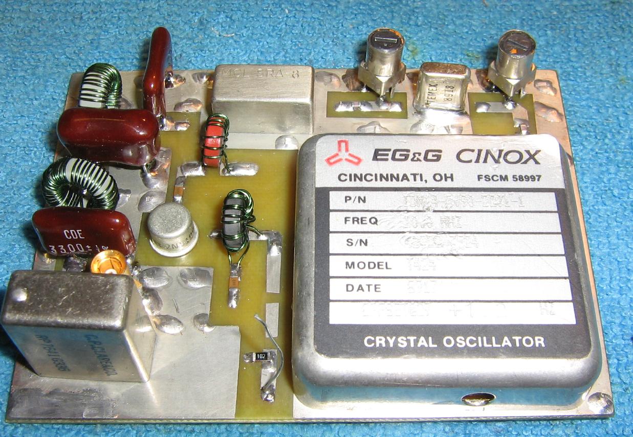
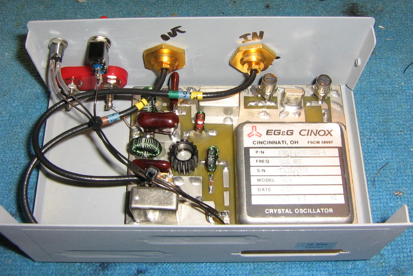
Overview of the GBPPR VLF Converter circuit.
The 5-pole low-pass filter is along the left-hand side.
The silver rectangle along the top is the Mini-Circuits SRA-8 mixer.
To the right of the mixer, is the optional 10 MHz crystal filter which is on the output of the 10 MHz TCXO, which is on the lower-right.
The 10 MHz TCXO is model number T424 and made by EG&G Frequency Products, Inc. This unit was discussed in much more detail in GBPPR 'Zine Issue #72. Its stock sine wave output is around 500 mV p-p with a 50 ohm load.
The large silver rectangle on the bottom-left is an optional RF relay used to switch the converter in-and-out. When the relay is not energized, the RF input to the VLF converter passes directly to the RF output, bypassing the frequency conversion circuit.
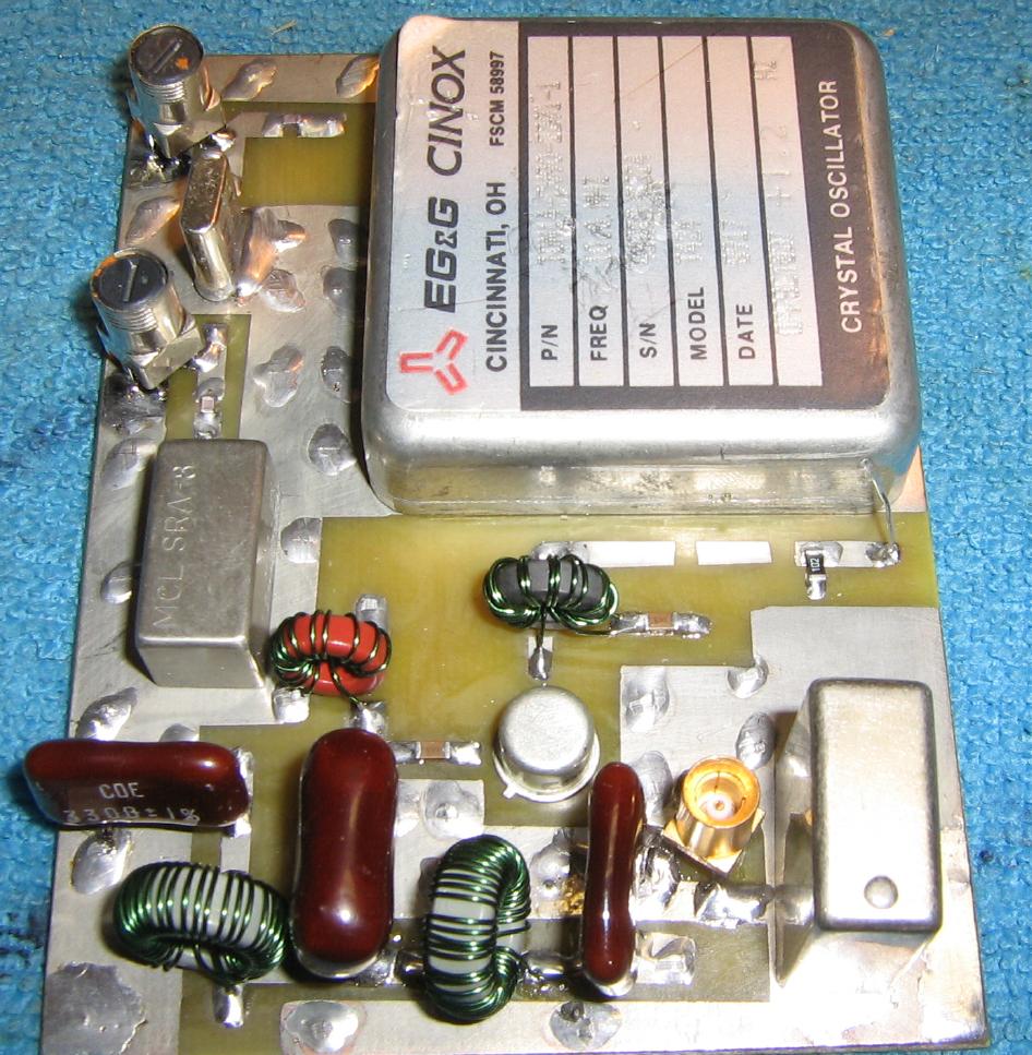
Alternate view of the GBPPR VLF Converter circuit.
Along the bottom are the silver mica capacitors and T-50-3 toroids (gray) making up the input 500 kHz low-pass filter.
The TO-5 transistor in the middle is the 2N5109 making up the post-mixer amplifier.
The T-37-2 toroid (red) makes up part of the post-mixer diplexer circuit.
The FT-37-43 toroid in the middle makes up the output impedance matching network for the 2N5109.
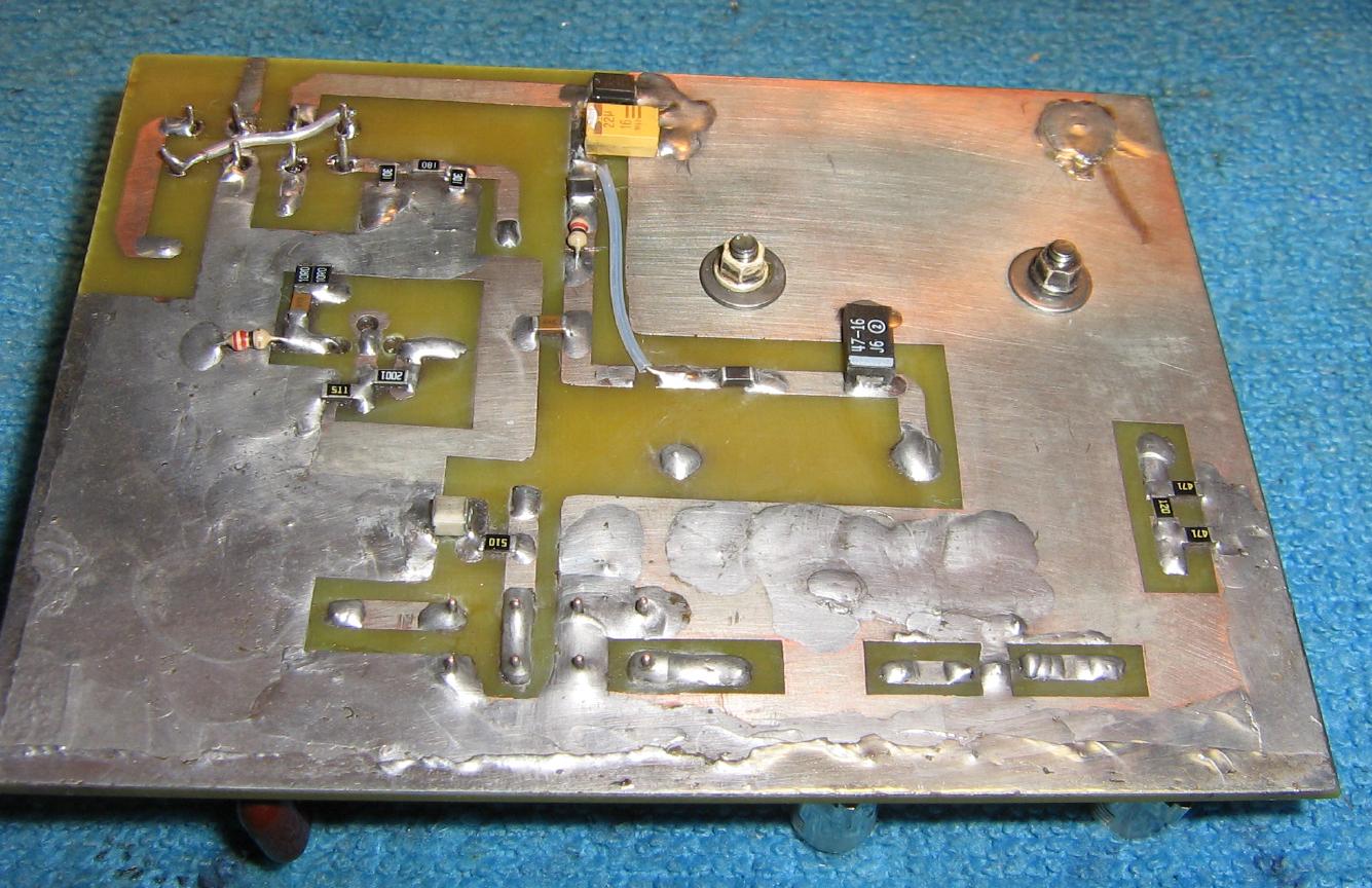
Bottom view of the circuit board.
A "psuedo double-sided" layout was used.
You'll want to use a large ground plane and observe proper RF layout techniques. Even though this circuit operates at low frequencies, it's still not a good ideal to skimp on the construction details.
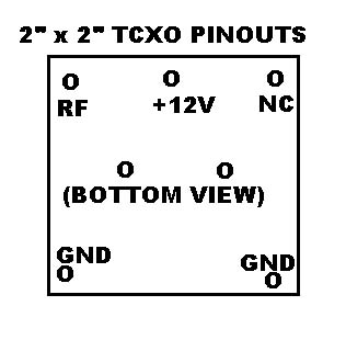
The pinout for the EG&G TCXO and the wiring diagram for the FT-37-43 toroid transformer are shown below:
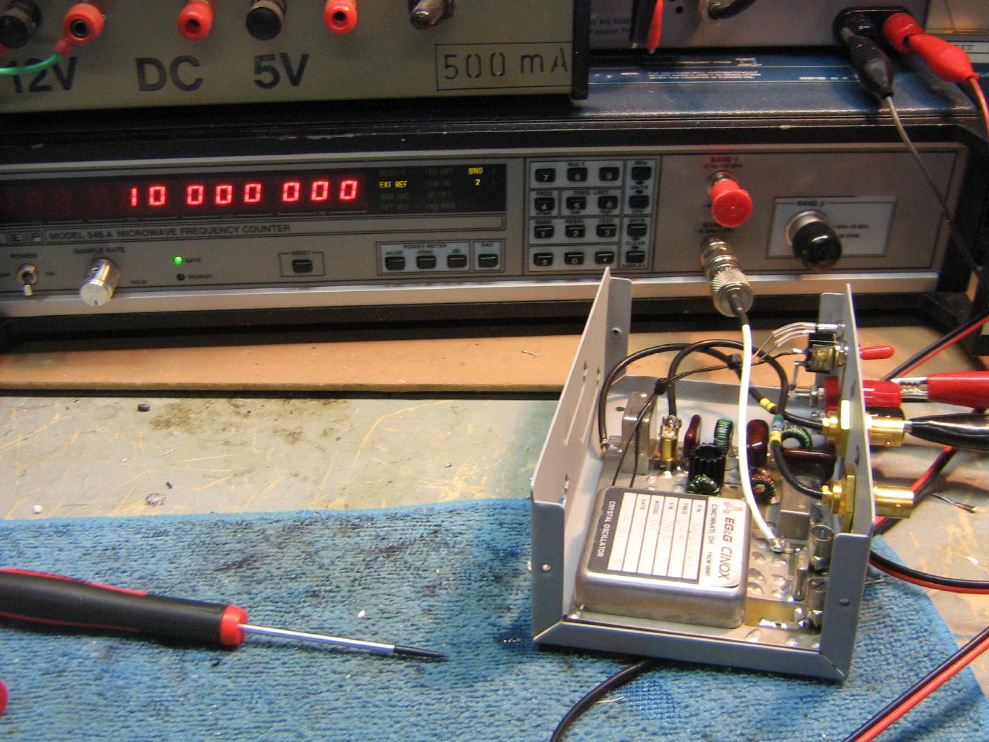
Adjusting the trimmer cap on the rear of the TCXO to provide a local oscillator signal of exactly 10 MHz.
You can "zero-beat" to WWV if you don't have an accurate frequency counter.
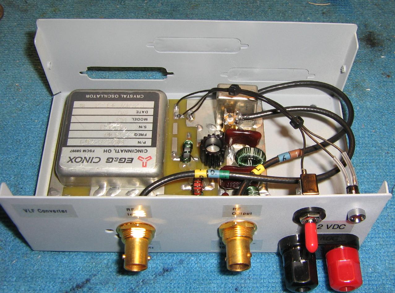
Mounting the circuit board inside an old printer switch case.
The banana jacks on the upper-left are for the +12 VDC power input.
A power LED and switch are mounted above it.
The two panel-mount BNC jacks are for the RF input and RF output.
Completed overview.
The 1 - 500 kHz RF input is via the left BNC jack. The 10.001 - 10.500 MHz RF output is via the right BNC jack.
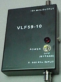
The VLF59-10 is an up-converter that moves 5 - 500 kHz to 10.005 - 10.500 MHz. Although specifically designed for use with the Avcom PSA 65x series of spectrum analyzers, it works well with any receiver that can cover its frequency range.
Operation: Connect the VLF59-10 BNC to the Avcom RF INPUT jack. The unit is supplied with two antennas that permit connection to the power line ground or telephone line. Other antenna configurations may be used as long as the wire is isolated with a capacitor having at least a 500 volt rating. Turn ON the VLF converter and AVCOM and set the REFERENCE LEVEL switch at 0 dBm, the SPAN switch at .2 MHz/DIV and the VAR SPAN at vertical. With NO antenna connected to the VLF59-10, tune the AVCOM to 10 MHz and locate the 10.000 MHz local oscillator signal of the VLF59-10. Slowly tune the Avcom to move this signal to the LEFT edge of the screen. Signals from 5 kHz to 500 kHz appear to the RIGHT of the 10.000 MHz signal. Connect an antenna. When the VLF59-10 is turned OFF the ANTENNA input is connected directly to the RF INPUT of the spectrum analyzer. Do not use the VLF converter with any of the AVCOM frequency extenders.
A single 9 volt Alkaline battery powers the unit. Normal battery life is in excess of 200 hours. Newer models convert 5 kHz - 5 MHz to 10.005-15.000 MHz.