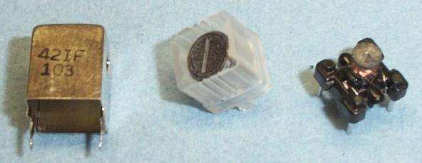
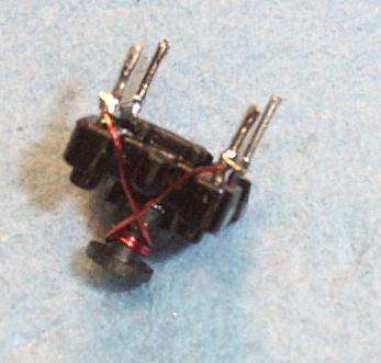
One of the most difficult parts of this project is making the modulation transformer for the transmitter section. It's not hard, but requires some patience. The transmitter's transformer is made from a modified Xicon 42IF103 455 kHz IF Transformer (Mouser Part # 42IF103). The three parts of the transformer are (left-to-right) the shield, the tunable ferrite cap, and the core.
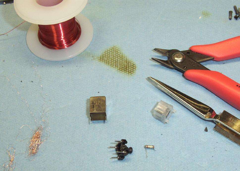
Start by taking the stock transformer apart. Heat it gently with a hot air gun and the transformer's core should just slide out.
Be sure to carefully study and document the transformer's original pin layout and construction, as you'll need to put it back together!
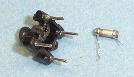
Next, cut the fine wire which is wrapped around the transformer's core. You'll need to unravel all the wire and de-solder it from the transformer's pins. Also be sure to remove the transformer's capacitor. It's the little brown/silver cylinder in the picture.
Close up of the bare transformer core and its internal capacitor. The center-tap pin on the transformer broke while removing it. It will still work.
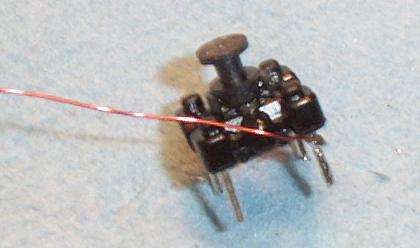
You'll need to add your own windings to this coil. Start with the SECONDARY winding. This will be three turns of 30-gauge enamelled magnet wire (Radio Shack Part # 278-1345). Start by stripping (with a X-acto knife) and tinning one end, then solder that to one of the pins on the transformer core.
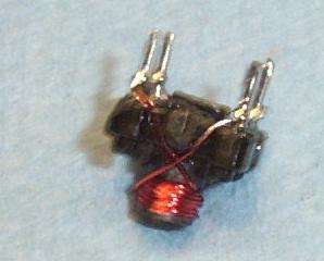
Completed SECONDARY winding. Be sure to use the correct pins.
Completed PRIMARY winding over the SECONDARY winding.
The PRIMARY winding will have twenty turns of 30-gauge enamelled magnet wire. It's final inductance should be around 10.2 µH. Its exact value is not too critical, as the ferrite cap allows the transformer to be "tweaked."
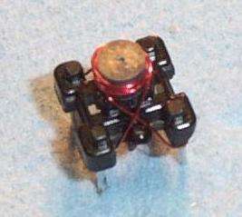
Overhead view of the completed transmitter transformer core.
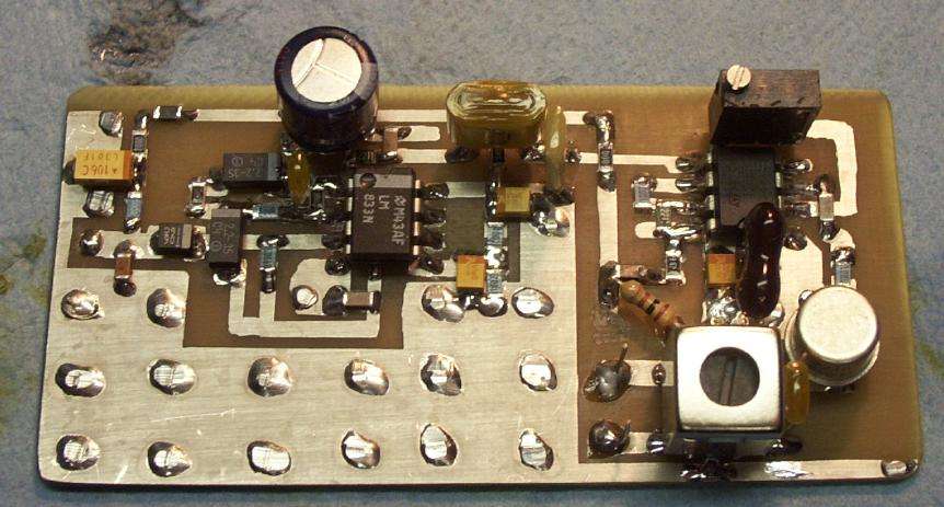
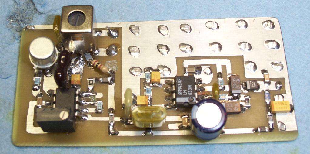
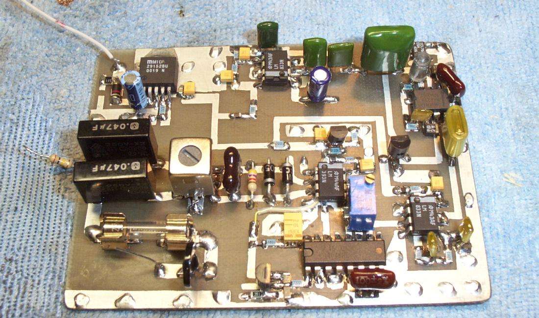
Carrier-current transmitter overview. Electret microphone input is on the left, and it feeds one-half of the LM833 op-amp. The gain is around 40 dB and it's set to roll-off around 7 kHz. The other-half of the LM833 acts as an active bias for the first op-amp. The output of the LM833 is sent through a simple RC low-pass filter to remove any remaining ultrasonic frequencies which could interfere with the FM carrier. It finally feeds a CMOS 555-timer configured to generate a square-wave carrier frequency at around 300 kHz. It's exact value is also not critical, but it should be near 300 kHz. The version shown above oscillates around 270 kHz (it will vary slightly with temperature), and works fine.
The audio input signal to the 555 frequency modulates the timer's 300 kHz carrier output. This output on pin 3 of the 555 is sent to a 2N2219A transistor. The capacitor/resistor/diode protect the transistor's base-emitter junction. In the transistor's collector path, is the PRIMARY of our new modulation transformer. This inductor value (10.2 µH) and a parallel 0.033 µF capacitor form a tuned circuit which is resonant around 300 kHz. Adjust the transformer's ferrite cap to "peak" the output from the transformer. The SECONDARY winding of the modulation transformer connects to the AC power line via a series 0.1 µF 250 volt, AC-rated capacitor. This capacitor has a reactance of around 26,525 ohms at 60 Hz and only 5.3 ohms at 300 kHz. This is how it can connect to the AC power line without blowing up.
Capacitive reactance is found via the following Perl equation:
$Cap_React = 1 / (2 * pi * $Frequency_in_Hertz * $Capacitance_in_Farads);
A parallel inductor/capacitor (LC) resonant frequency is found via the following Perl equation:
$Frequency_in_Hertz = 1 / (2 * pi * (sqrt ($Capacitance_in_Farads * $Inductance_in_Henries)));

Example: 0.033 µF and 10.2 µH in parallel = 274.3 kHz
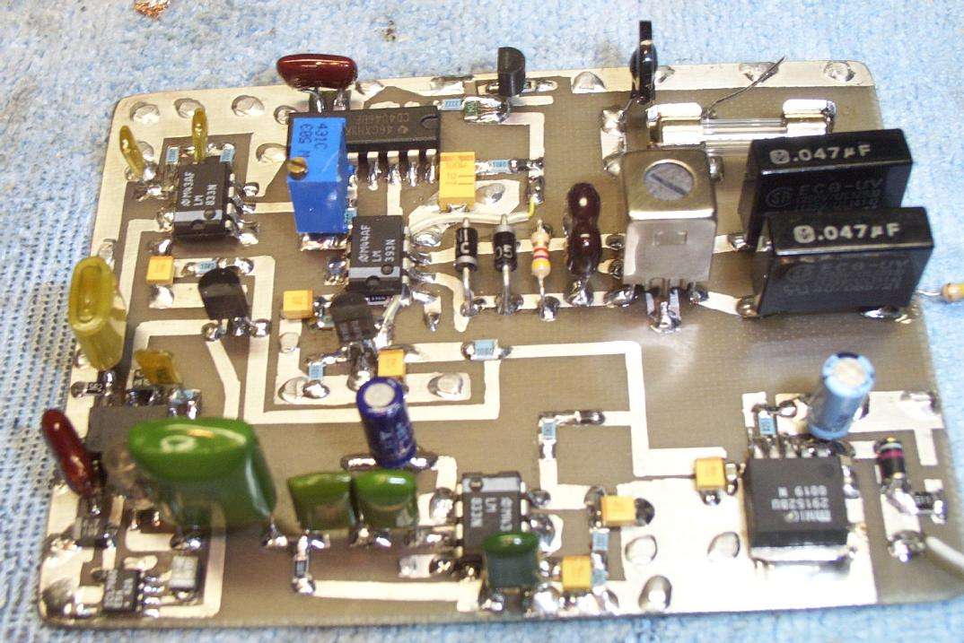
Alternate view of transmitter. It varies a bit from the schematic due to experimenting.
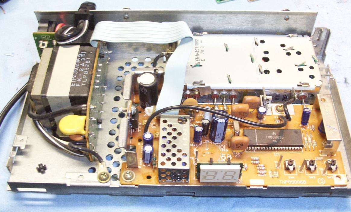
Internal picture of a cable box where the bug will be planted for this experiment. This cable box was chosen for a varity of reasons. There is alot of room inside, it offers a "loop-through" AC output on the back for easy connection, it is always powered on (remote control activated devices never actually power down), it uses a linear power supply so there is no switching noise, and the voltage regulator is a common 7812, so tapping into its output lines is quite easy.
Internal view of the cable box. The 7812 voltage regulator is shown in the middle. Its output is the right-most pin.
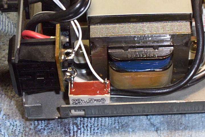
Close up view of the AC input and step-down transformer inside the cable box. The loop-through socket is on the left with the series 0.1 µF capacitor.
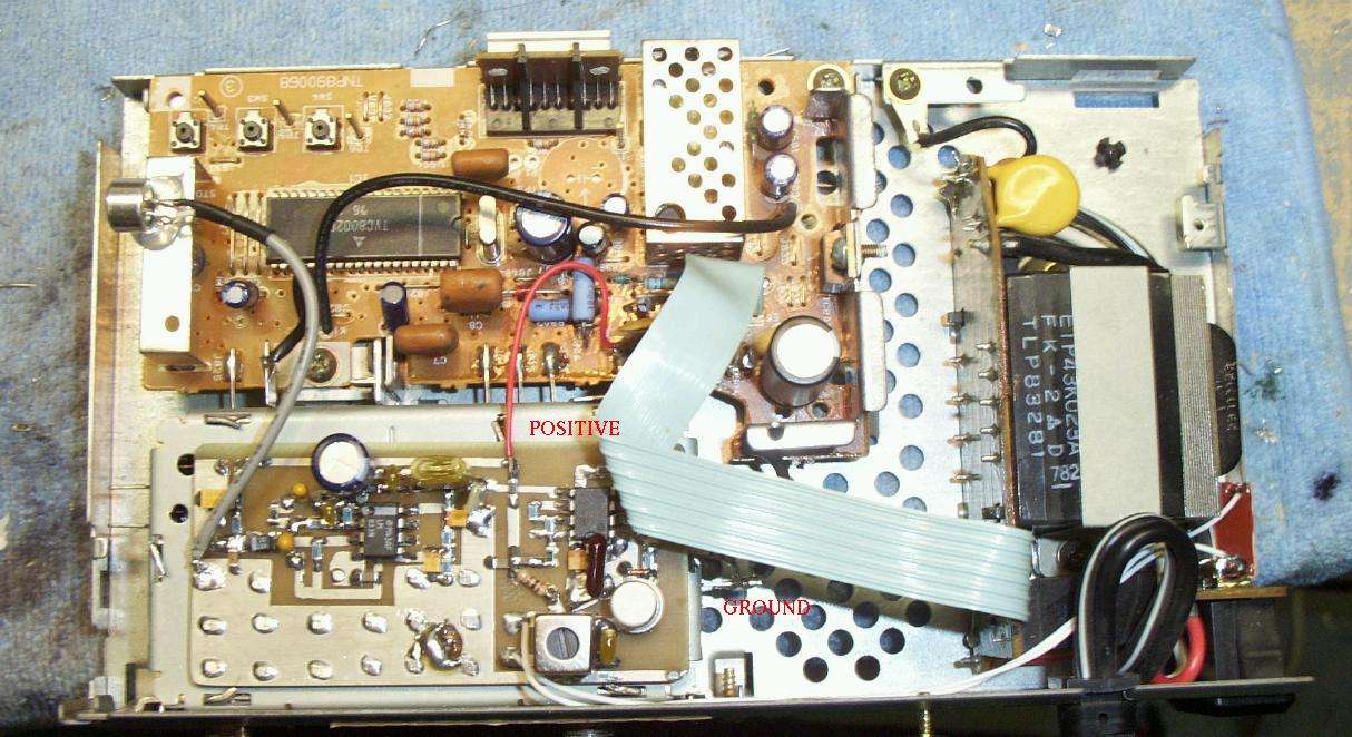
Carrier-current surveillance bug planted inside the cable box. The red wire taps the cable box's +12 VDC. The small braid connection on the right is the circuit's ground. The microphone is positioned such that the audio can enter via the ventilation slots on the side of the case.
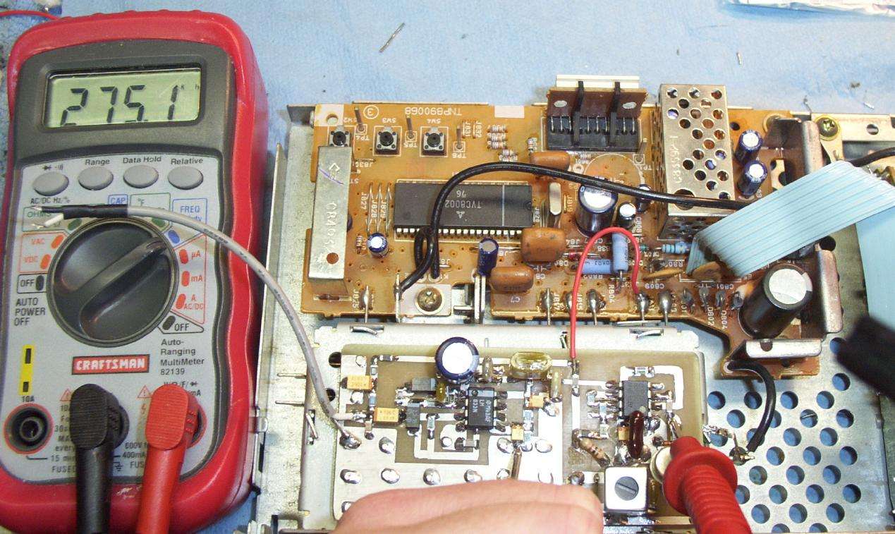
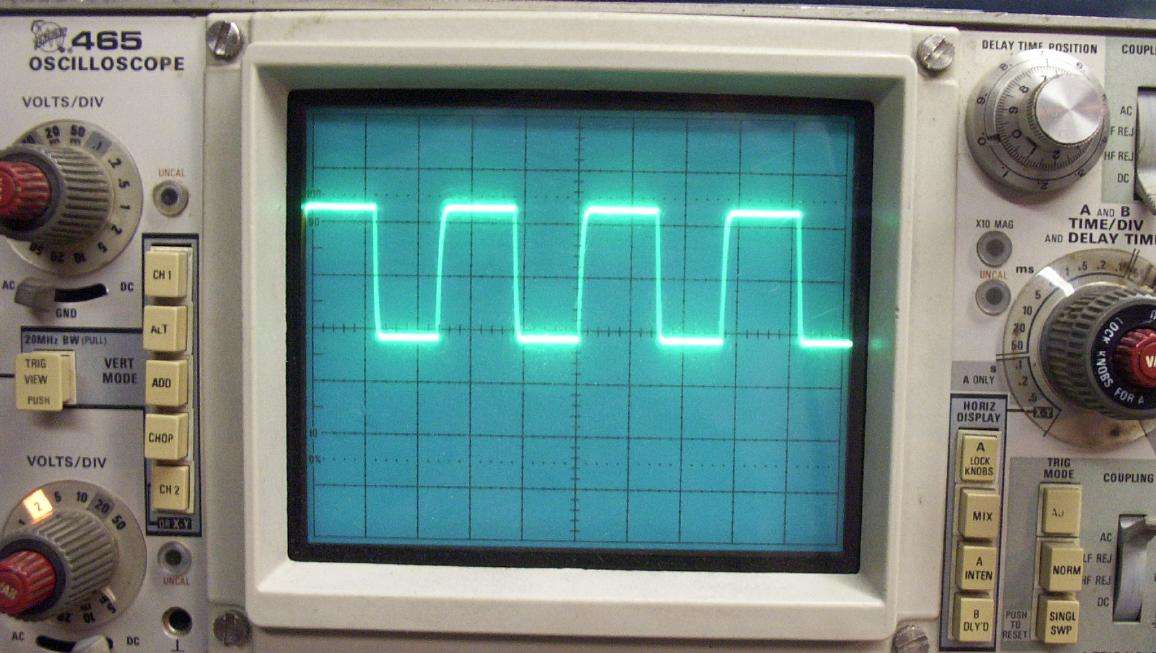
Checking the 555-timer's carrier frequency at Test Point #1 (TP1 in the schematic). The carrier frequency is reading 275.1 kHz. This is close enough to the target frequency of 300 kHz.
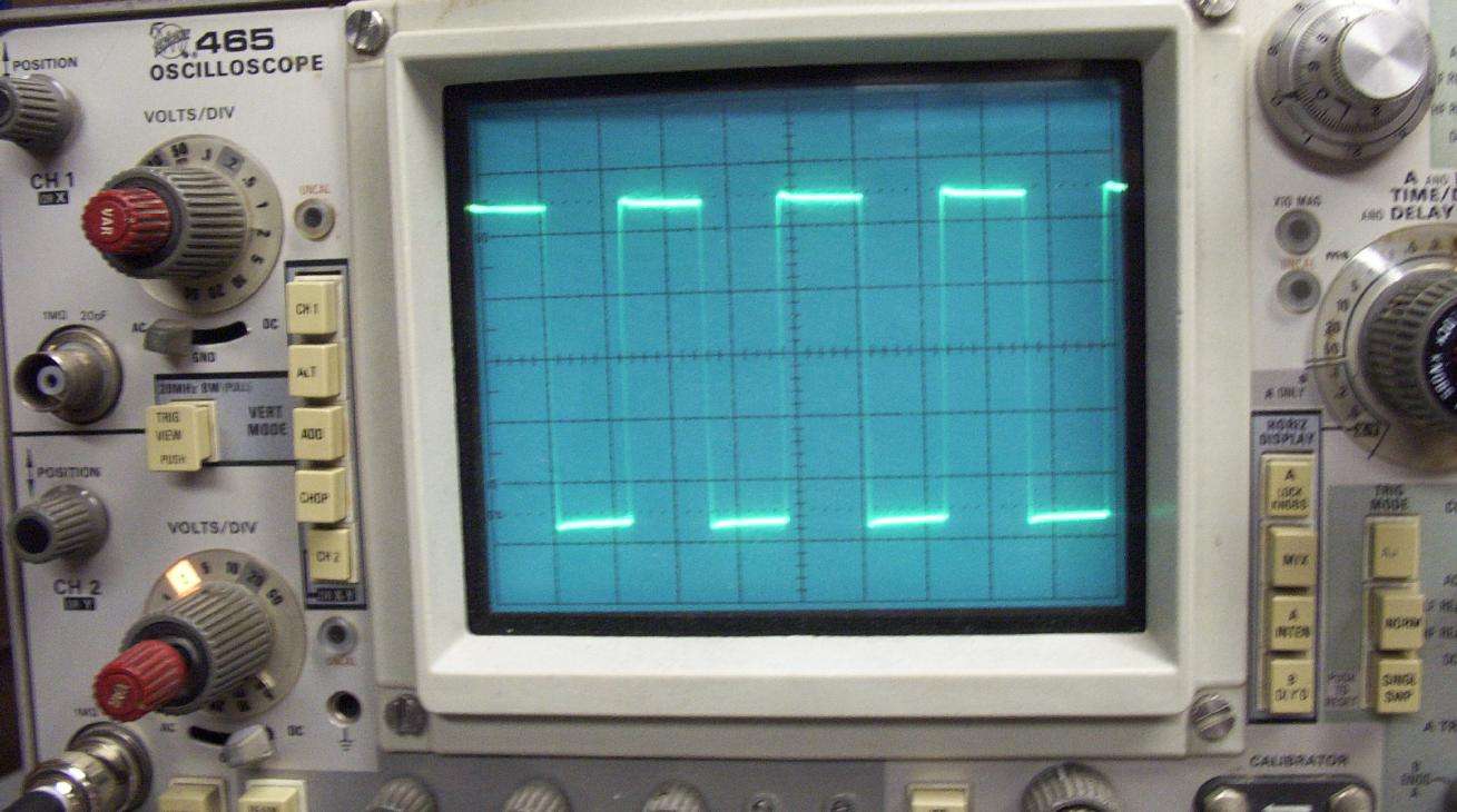
Oscilloscope view of the waveform at Test Point #1.
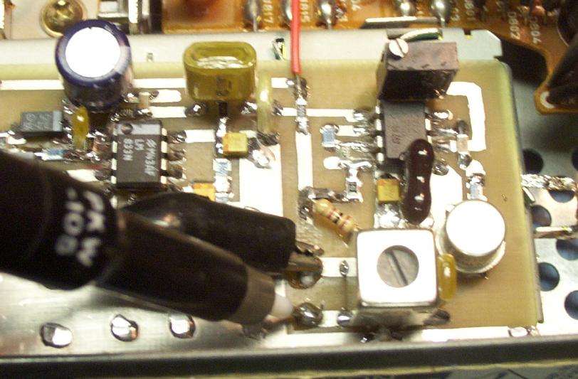
Peaking the output of the modulation transformer. Connect it to an oscilloscope and "peak" the output waveform by adjusting the ferrite cap inside the transformer with a plastic tuning tool.
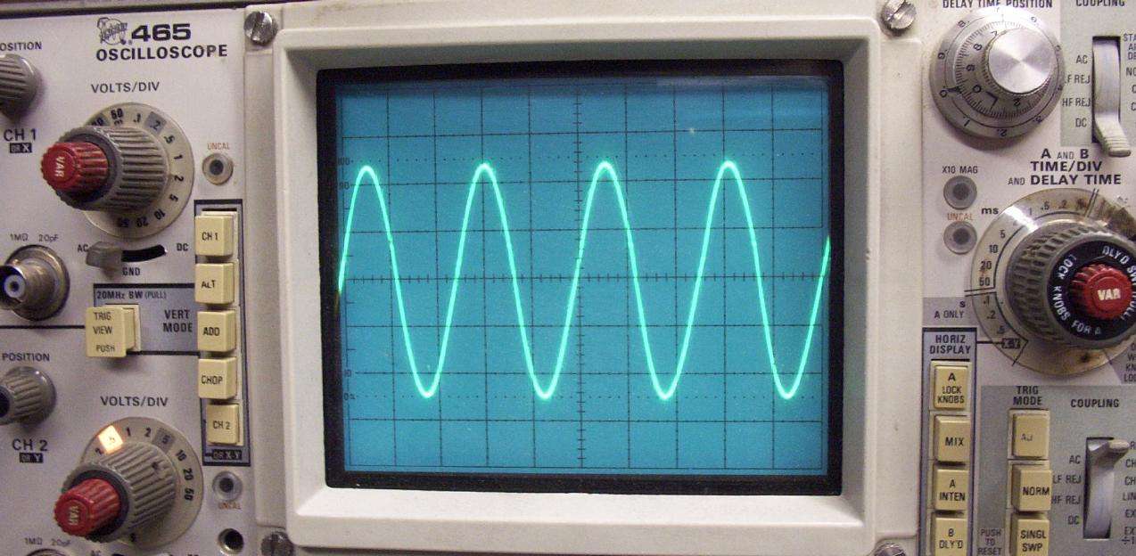
Oscilloscope view of the transmitter's modulation transformer peaked output waveform.
Picture of the carrier-current receiver board. It too differs from the schematic due to experimentation. The AC line input is on the lower-left. One side passes through one of those low-value resistor things that are found in switching power supplies, then through a 250 mA fuse, then a series 0.1 µF 250 volt, AC-rated capacitor. It is then connected to the SECONDARY side (the side with only two pins) of a stock Xicon 42IF103 455 kHz IF transformer. The modulation output is taken on the PRIMARY side of the transformer, and the transformer's center-tap must be grounded. This is important to properly bias the LM393. An external, parallel 330 pF capacitor lowers the resonant frequency of the transformer's tuned circuit to around 270 kHz. The 42IF103, in its stock 455 kHz configuration, has an inductance value of 680 µH and capacitance of 180 pF. A parallel 4.7 kohm resistor lowers the Q of the tuned circuit, making "off-frequency" reception possible. Two back-to-back diodes clip the waveform going into the LM393 to avoid overloading.
The LM393 is configured as a zero-crossing detector. It turns the received 300 kHz sine wave into a series of square waves. These square waves should look similar to those of the 555-timer in the transmitter. They are directly coupled into a CD4046 phase-lock loop IC configured as a FM demodulator. The CD4046 generates its own carrier frequency near 300 kHz. This internally generated frequency is compared to the input frequency. The resulting phase "difference" in the two frequencies is caused by the audio modulation. The CD4046 outputs this phase difference signal on pin 10. It is then buffered and low-pass filtered to strip the carrier by a LM833 op-amp. You'll notice that the LM393 and the CD4046 are both run from a TL431 precision, low-noise +5 VDC regulator. This help keeps the CD4046's internal oscillator on frequency. It is optional, but recommended.
The signal passes through another LM833, this time configured as a 300 Hz high-pass filter. This helps to remove any 60 Hz hum or low-frequency rumbles. It passes through a 10 kohm volume potentiometer (with an integrated switch) and then onto a MC34119 (or NJM2113) audio power amplifier. Headphones or a low-power speaker can be driven.
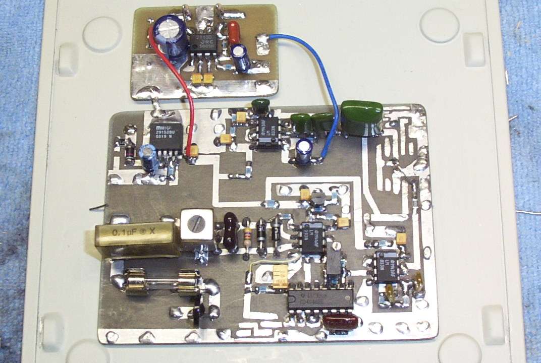
Alternate view. A Maxim MAX295 was inserted to try and remove some of the in-band noise, but it didn't work too well. Total noise removal might require DSP filtering or digital modulation. Also, on pin 1 of the CD4046, was an attempt to use the loop unlock signal for something, that didn't work out either. Only one 0.1 µF capacitor is really needed on the AC line input. The voltage regulator is a Micrel MIC29152, configured for +9 VDC.
Waveform of the LM393's output going into pin 14 of the CD4046. It should be fairly close to a square wave. Adjust the LM393's 1 Mohm feedback resistor (up to 10 Mohms) to fiddle with the waveform.
CD4046's internal oscillator output at Test Point #2 (TP2 in the schematic). Measure this without the receiver connected. It should be near the target carrier frequency of 300 kHz. This particular unit was measured at 263 kHz, with the parts shown in the schematic.
Completed receiver with a NJM2113-based audio amplifier mounted on the side. The final audio amplifier can be replaced with a high-power version, like a LM380, for driving a bigger speaker.
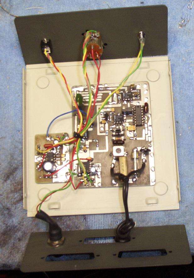
Installation in the case. Power is provided via a wall-wart power supply (lower-left). A separate AC power cord is used for the carrier-current pick-up (lower-right). The top panel, from left-to-right, is the headphone jack, volume pot and on/off switch, and a power LED.
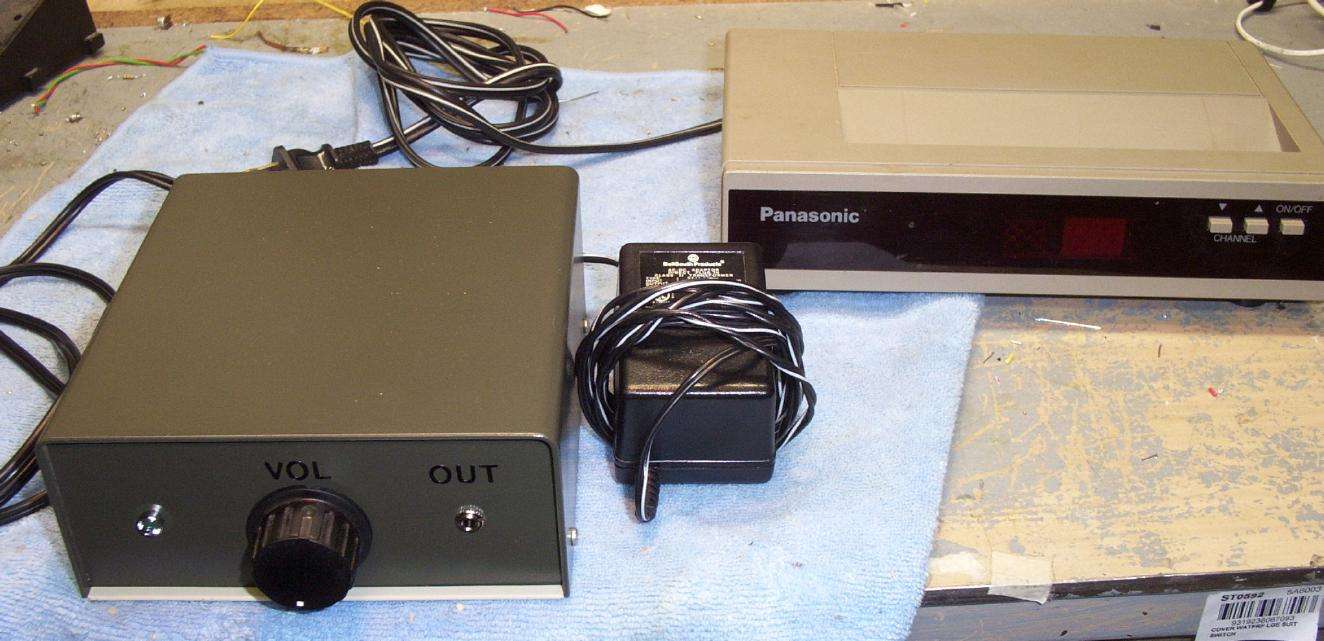
Completed carrier-current receiver (left) and the transmitter hidden inside a cable TV converter box (right). The receiver is using an external wall-wart DC power supply. The AC pick-up is from a separate power cord coming out the back. To connect the receiver to something other than AC power lines (say, phone lines), build a breakout box from an old outlet and run the lines into that.
