The goal of the project described here is to develop a prototype NDE tool for inspecting bridge decks. The system design is based on concepts developed at LLNL under its Ground Penetrating Imaging Radar (GPIR) development project 1, 2. The prototype is intended to demonstrate concept feasibility and enable the Department of Transportation (DOT) to demonstrate the technology to its customers. The system will collect inspection data and produce high-resolution images enabling users to visualize bridge deck internal structural features and flaws.
Damage caused by corrosion is hidden from the view of inspectors by concrete and overlaying asphalt layers. Corrosion problems are usually found in the top layer of rebar in the deck, under a 2 inch cover layer of concrete and up to 4 inches of asphalt pavement. Delamination of deck concrete occurs when rebars corrode after long-term exposure to chloride ions and moisture that penetrate into the concrete. Corrosion products generated during this process produce tensile forces within the surrounding concrete which eventually cause fracturing and cracking. As the corrosion process progresses, cracks form between adjacent rebars which delaminate the top layer of concrete from the underlying structure. Figure 1 illustrates the effects of corrosion and resulting concrete delamination.
Delaminations effectively decouple the concrete from rebar strengthening members resulting in a loss of structural strength and a rapid deterioration of the deck wearing surface. The resulting damage is costly to repair and usually results in bridge closure during restoration. If it goes undetected, delamination can progress to a point where the entire bridge deck, including structural reinforcement, must be replaced. Timely identification and location of this condition would permit remedial action to be taken before failure could occur, and it could enable bridge operators to prioritize spending on bridge maintenance on the basis of structural need.
A vehicle mounted imaging radar for bridge deck inspection, designed to collect inspection data at or near normal traffic speeds, has the near-term potential to address a critical national and international need for reliable, cost effective NDE of bridges. To be effective, it is important that the bridge deck inspection system have a high probability of detecting rebar delaminations. Detection capabilities will depend primarily on the ability of the radar to detect thin layers or voids. We are evaluating that capability experimentally. In addition, high cross-range resolution will be required to accurately characterize and map the extent of delaminations that are detected.
The proposed concept includes three inspection modes to provide operational flexibility. These modes are:
Quick Inspection Mode: Provides a means to collect inspection data while minimizing the impact of the inspection on traffic flow. This mode offers the highest inspection vehicle speed, the lowest resolution, and the highest data storage capacity. This mode is intended for preliminary assessments of deck condition and should provide an inspector with data that is adequate to determine if more detailed inspections are needed.
Limited Depth Inspection Mode: Provides a means for collecting high-resolution data to a depth that permits evaluation of the top layer of rebars while maximizing inspection vehicle speed. The resolution in this mode is the same as for the detailed inspection mode enabling identification of areas of bridge deck where delaminations in the top layer of rebar are a problem.
Detailed Inspection Mode: This mode provides the highest resolution and the lowest vehicle speed. It also enables collecting inspection data for the full thickness of the bridge deck, up to a maximum thickness of 40 cm.
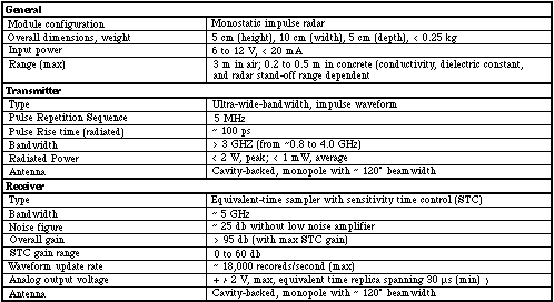
The prototype bridge deck inspection system uses arrays of MIR modules configured as range-finding radars. The range-finder is a compact, low-cost ultra-wideband radar with a swept range gate. The range-finder uses a unique equivalent-time sampling system (similar to those used in sampling oscilloscopes, but much lower in cost) which reduces ultra-wide-band signal bandwidth by as much as three orders of magnitude, with no loss of information content. Lower bandwidth, equivalent-time radar return signal replicas can then digitized using low-cost analog-to-digital converters. Technical specifications for a single range-finder module, designed for use in the bridge deck inspection prototype, are summarized in Table 1.
Cross-range resolution is achieved by forming a large aperture and populating it with sensors like the MIR modules. Since individual MIR elements are low in cost and compact, it is feasible to connect several elements into a compact array to span the desired aperture. The resolution achieved depends on the wavelength, range, single element beam pattern, element spacing, and overall dimension of the aperture. A large aperture can be real or it can be synthesized by scanning a smaller aperture device (a single antenna or a small array) to fully sample the desired aperture. In our most recent experiments (reported below), we synthesized a 0.8 meter aperture, using a single MIR module, with 1.6 cm element spacing and achieved cross range resolution of <5 cm at ~12 cm depth (beneath 5 cm of asphalt and 7 cm of concrete).
To achieve high resolution in both cross-range directions, it is necessary to form a 2-D synthetic array. In our experiments, we did this synthetically by scanning a single MIR element in a raster scan pattern. In a bridge deck inspection operation it is more practical to use a 1-D array and scan once in the orthogonal dimension to form the synthetic 2-D aperture.
LLNL has developed diffraction-tomography and time-domain based imaging software necessary to reconstruct the 2-D and 3-D images 3, 4. The software is written in portable C code, and can run on a workstation or laptop portable computer.
In our experiments, we used a single MIR module to synthesize a 2-D aperture. Data collected in this manner was used to calculate a 3-D image of the volume and internal details of each slab. The aperture size used for these experiments was 80 cm by 75 cm, and the radar was maintained at a distance of 3 cm above the surface of the slab. The radar used to collect this data has a peak radiated power of <100 mW, usable spectrum from ~800 MHz to <4 GHz, pulse repetition frequency of 2 MHz, and receiver gain of ~90 dB. In our experiments, we focused our attention on the smallest and thinnest delamination simulations.
Figure 8 is a set of 2-D planar slices through the calculated 3-D image of Slab 1; the slices are parallel to the surface of the slab. In the figure, at a depth of 5.5 cm, both the 4-inch by 4-inch by 1/8-inch thick and the 6-inch by 6-inch by 1/8-inch thick delaminations are clearly visible. At the 5.5 cm depth, rebar used in the construction also begins to appear. The rebars appear here because of the construction of the rebar mat used in the slab. Note in Figure 4, the top layer of rebar is constructed with overlapping rebars placed at the edge of the slab. It is the overlapping rebar pieces, which are positioned above the spanning rebars, that appear first at the 5.5 cm depth in the 3-D image. The overlapping rebars are also evident at the 8.5 cm depth, and the second (orthogonal ) layer of rebar appears at the 10 cm depth.
Figure 9 is a set of 2-D planar slices through the 3-D image of Slab 2. This slab has a 2 inch thick overlay of asphalt over the reinforced concrete. In the figure, at a depth of 10.5 cm beneath the asphalt surface, the 1/8-inch thick delaminations are also clearly visible. At a depth of 13.5 cm, the top rebar mat appears. Again, the overlapping rebars are clearly displayed at this depth. Finally, at the 15 cm depth, the second layer of rebar appears.
Mast, J.E., and E.M. Johansson, Three-Dimensional Ground Penetrating Radar Imaging Using Multi-Frequency Diffraction Tomography, SPIE Vol. 2275, Advanced Microwave and Millimeter Wave Detectors, July 25-26, 1994.
Nelson, S.D., Electromagnetic Modeling for Ground Penetrating Radar Using Finite Difference Time Domain Modeling Codes, SPIE Vol. 2275, Advanced Microwave and Millimeter Wave Detectors, July 25-26, 1994.
Warhus, J.P., J.E. Mast, E.M. Johansson, and S.D. Nelson, Advanced Ground Penetrating Radar, SPIE Vol. 2275, Advanced Microwave and Millimeter Wave Detectors, July 25-26, 1994.
Table 1. MIR Module Specifications for Bridge Deck Inspection Radar

Table 2. Baseline System Performance Goals
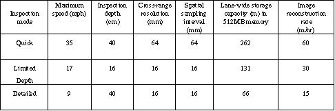

Figure 1. Concrete Delamination Caused by Corrosion of Steel Reinforcement

Figure 2. Bridge Inspection Vehicle Concept

Figure 3. Micropower Impulse Radar Circuit Board
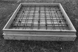
Figure 4. Concrete Slabs Used in Delamination Detection Experiments
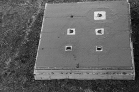
Figure 5. Layout of Concrete Slabs Used in Experiments
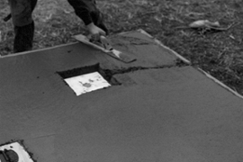
Figure 6. Two-Dimensional Planar Slices of Delaminations and Rebars in Slab 1
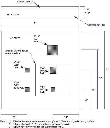
Figure 7. Two-Dimensional Planar Slices of Delaminations and Rebars in Slab 2