This is a simple little 800 MHz band cellular phone jammer which can be easily built from commonly available parts. Most homebrew cellular phone jammers are based around a sweeping RF oscillator which, while more "jamming" efficient, can be quite difficult for the beginner to construct without access to expensive RF test equipment. This project can also be used to help take the load off certain people who receive 15 million emails a day from strangers asking them how to build their own cellular phone jammers...
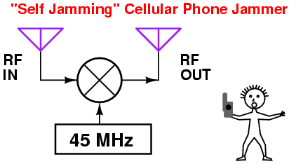
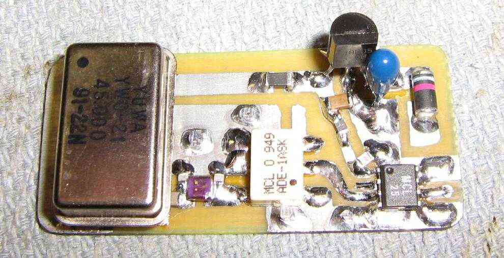
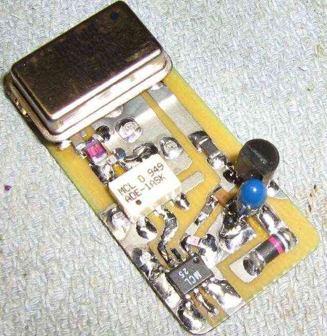
This cellular jammer is based around a common 45 MHz clock oscillator driving the Local Oscillator (LO) port on a Mini-Circuits ADE-1ASK mixer. This LO signal also passes through a simple impedance matching network to transform the high impedance of the clock oscillator down to the mixer port's 50 ohm impedance.
The mixer's RF port (RF input) is connected directly to a 800 MHz band cellular phone antenna, and the IF port (RF output) is sent to a Mini-Circuits VNA-25 MMIC amplifier which increases the output jamming power by around 16 dB. This is then sent onto another 800 MHz band cellular phone antenna.
Here's the theory of operation... Any cellular phone that attempts to call out is immediately "jammed" by its own signal! This works because every 800 MHz band cellular phone's transmit and receive frequency are always separated by exactly 45 MHz.
Example: Say your cellular phone is transmitting at 837 MHz and receiving at 882 MHz. If you were to mix the 837 MHz transmitted signal with a 45 MHz signal, the new mixer output frequency would be 882 MHz - and the phone would essentially be jamming itself by "hearing" its own signal. This appears to work quite well on most cellular phones and should also work on full-duplex Nextel transmissions.
These types of jammers are also useful for defeating cellular-based vehicle tracking systems which record your travels via GPS then "burst" out a phone call in the middle of the night. It should also be useful for defeating GM's OnStar system and maybe even cellular phone detonated IEDs.
