 <--- NBFM DSSS --->
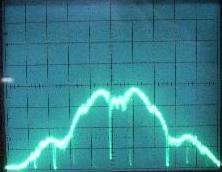
<--- NBFM DSSS --->
Spread Spectrum (SS) audio surveillance transmitters are used to prevent the accidental, or intentional, reception of the RF signal by an external party. They offer fairly strong protection from small-time listeners (ham radio/scanner operators) and even protection from some of the "lesser-informed" Technical Surveillance Counter Measures (TSCM) sweepers. Anyone with a good spectrum analyzer (or a good physical sweep) will be able to track this transmitter down.
The best part about this particular transmitter is - there is nothing to build! Direct Sequence (DS) and Frequency Hopping (FH) spread spectrum audio transmitters can be bought at your local consumer electronics store in the form of "high-security" cordless phones. You can even pick these phones up at thrift stores and rummage sales for only a few dollars. People will often throw away the entire phone when the rechargeable battery pack dies. I've picked up a few of these phones, and every single one worked when powered from a new battery or external DC power supply.
The cordless phone used in this project is a GE Model No. 2-911SSTA, labeled: "Digital 900 MHz Spread Spectrum Cordless Phone", and the FCC ID is G9H2-910SST. The base transceiver requires +9 VDC at around 600 mA and the handset needs +3.6 VDC / 200 mA. The handset transmit frequency is centered around 926 MHz and is about 4 MHz wide.
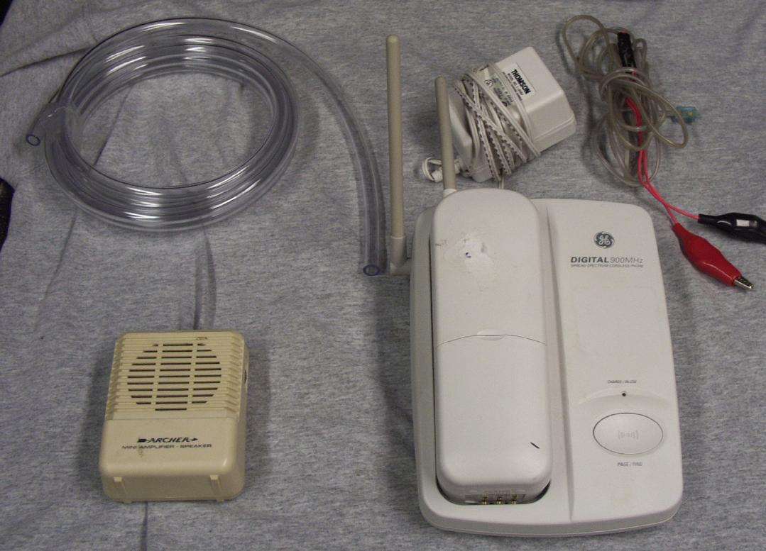
Tools you'll need. Clockwise from the upper left, a length of 3/8-inch I.D. flexible tubing, a RJ-11 phone jack which terminates with a set of alligator clips, the spread spectrum cordless phone, and a "Radio Shack Mini-Amplifier / Speaker", part number 277-1008C. You'll also need some sort of adapter to connect the RJ-11/alligator clips to the mini-amplifier, if you don't want to take the amplifier apart.
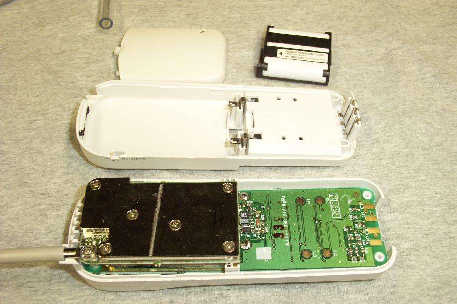
Inside view of the cordless phone's handset. This will become the actual "bug." The plastic case, keypad, speaker, and battery can be removed.
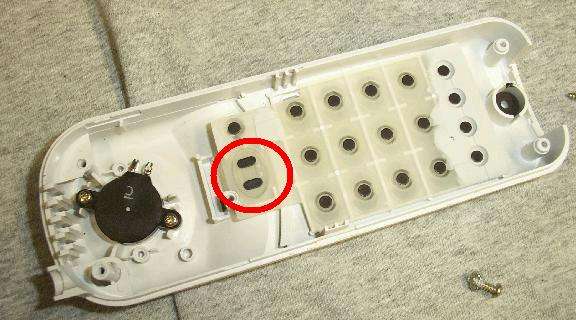
Make a note of the "Talk" button on the keypad. You'll need to solder jumpers across the circuit board pads for this key to permanently place the handset into "transmit" mode.
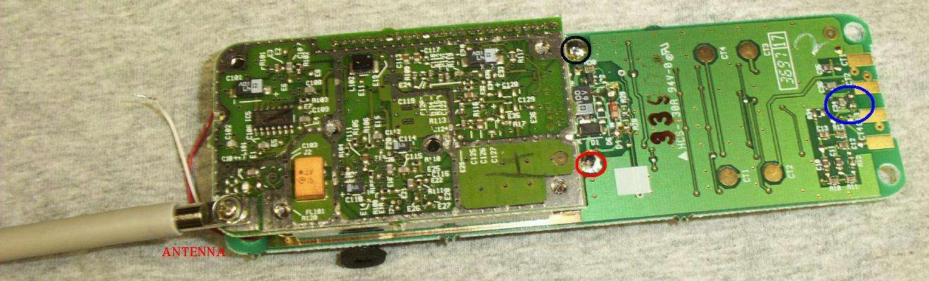
Closeup internal view of the handset. The antenna/RF section is on the left. The RED circle indicates the POSITIVE (+3.6 VDC) connection for the battery, the BLUE circle indicates the NEGATIVE or GROUND connection for the battery. The BLACK circle is the solder connection for the handset's internal electret microphone. You may want to replace the phone's original electret mic with one that has better sensivitity and signal-to-noise ratio, but that's optional.
Also, some cordless phones utilize "noise-cancelling" microphones. These should be replaced as they don't offer the best sensitivity for surveillance purposes.
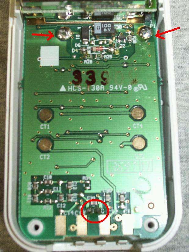
Alternate view of the above connections.
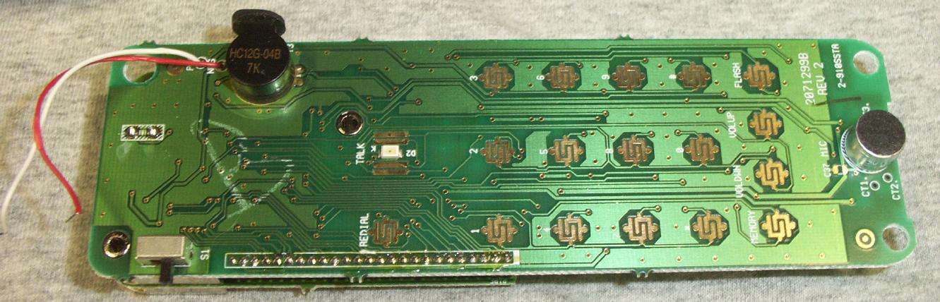
Closeup view of the keypad side of the handset's circuit board. The speaker has been removed. The black plastic thing on the left is the handset's ringer/buzzer. The handset's electret microphone is mounted on the right. Note the circuit pads marked "Talk". That is a surface-mount LED between them.
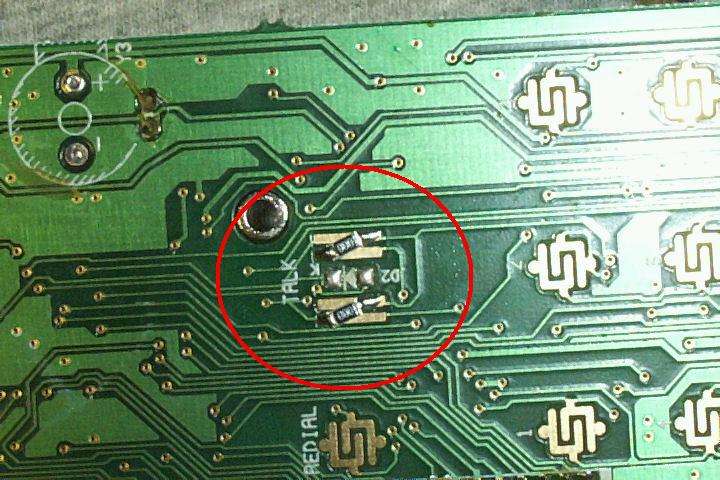
Closeup view of two zero-ohm resistors installed across the exposed pads of the "Talk" button. Most phone's will be different, but the overall theory should be the same. This forces the handset into "continuous transmit" mode the instant it powers up. The surface-mount LED and the ringer/buzzer have also been removed.
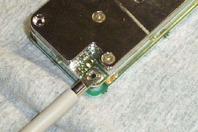
The handset is put back together. The antenna has been soldered to its circuit pad instead of using hardware. This actually increases the output RF power slightly as the electrical connection is much better.
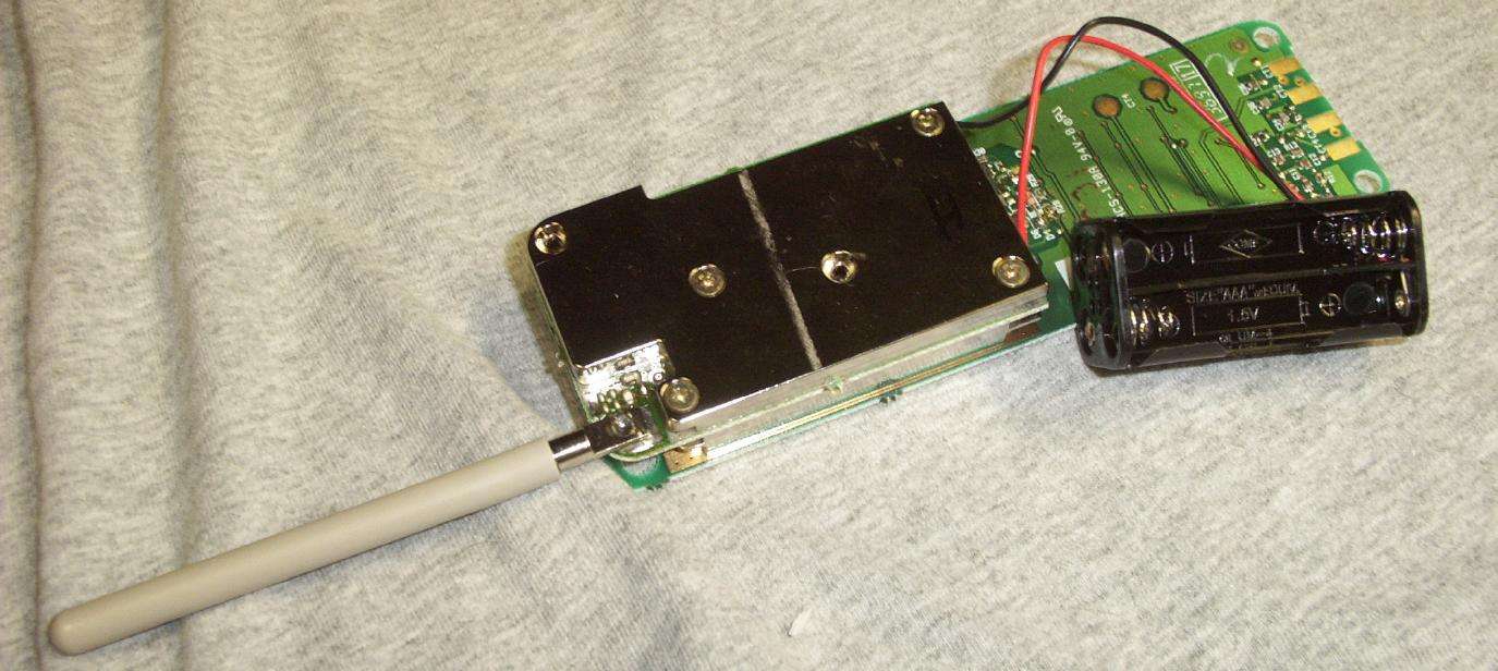
The completed surveillance bug. The DC power supply comes from four "AAA"-size batteries. You should use NiCad rechargeable batteries as these only output 1.2 Volts each (+4.8 VDC total). The use of regular alkaline batteries will require the use of some type of voltage regulator to reduce the input voltage to under +5 Volts.
As soon as the batteries are put in, this bug will start transmitting. Be sure the cordless phone base station is powered and ready (and in radio line-of-sight) so the handset can "sync" its signal, otherwise the handset will require a complete power-down (removal of the batteries), and this could be difficult in covert operations.
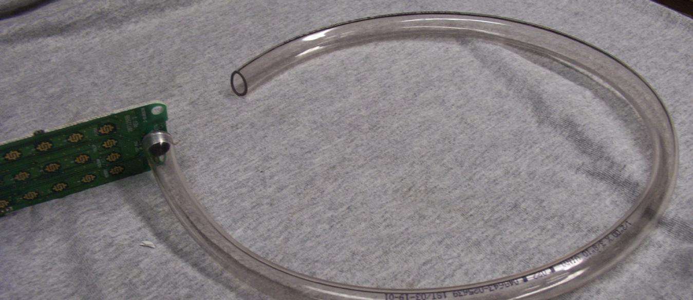
This is what the tubing is used for. When you don't want, or can't, extend the wires of the electret microphone, just place a piece of tubing over the mic and run the tubing to the location which needs to be monitored. The tubing can be run a considerable distance with no degradation of audio quality. Be careful not to break the microphone leads though.
Placing your transmitter/microphone at the end of a length of tubing is also a good way to defeat some metal detectors and non-linear junction detectors during a TSCM sweep.
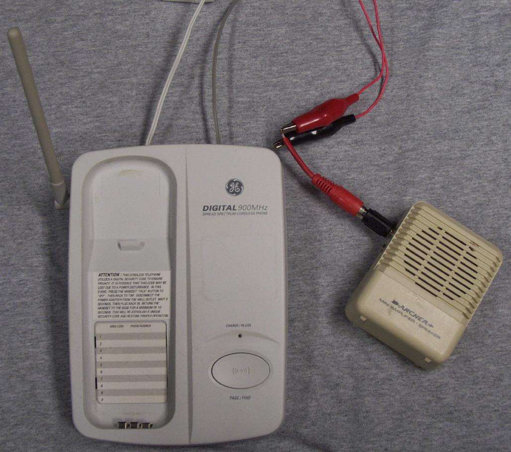
Base station "listening post" setup. Not really much is needed. Power the base station off the phone's standard wall-wart power supply. Instead of connecting the base station to the phone line, connect the output of the RJ-11 jack (via the alligator clips / adapter) to the mini-amplifier. You can also use a tape recorder in place of the amplifier, or even a lineman's handset. Polarity of the audio coupling should not matter.
If the base station needs to see phone line "off-hook voltage" before it starts to transmit, connect a +9 Volt battery to the tip & ring of the RJ-11 connection and take the audio off the line via a 0.1 µF DC blocking capacitor.
See GBPPR 'Zine, Issue #7 for more information on a high-performance 900 MHz receiving setup.
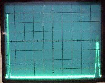
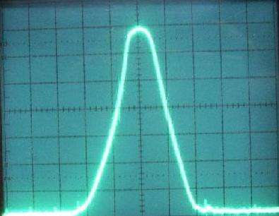
GBPPR Spectrum Analyzer view of the RF output. A conventional narrowband FM trasmitter at 845 MHz is shown on the left, the direct sequence spread spectrum signal (at approximately 926 MHz) is on the right.
Schematics for the GBPPR Spectrum Analyzer are available at: http://www.qsl.net/n9zia/spec/index.html
Notes
The following was from a post on the "TSCM-L" list maintaind by James M. Atkinson: http://www.tscm.com
To: TSCM-L@tscm.com
From: "James M. Atkinson, Comm-Eng" <jmatk@tscm.com>
Subject: Spread Spectrum Update

Several weeks ago I had a chance to examine a number
of spread spectrum microwave bugging devices.

Since that time I've conducted some analysis and
gathered further intelligence on the circuit.

Here are a few of my observations.

   =======  C O N F I D E N T I A L  ========

1) Most of the products use a high bandwidth QPSK/BPSK
modulator, multi channel audio CODEC, and a RISC
micro-controller chip (all components are either
surface mounted ICs or multiple dice potted in epoxy).

2) RF Circuit seems to be a simple homodyne audio
transmitter (6 Ghz Gilbert Cell Mixer) which is driven
by a single CPU/microcontroller (with a clock speed of 180 Mhz).

3) Frequencies used for the ultra low power device are
clean from 130 Mhz to 4 Ghz, circuit starts to fail
above 5.5 Ghz (but is still operable to about 8 Ghz).

4) Emitter is driven directly from vector modulator chip,
with no power amp circuits. PIN diode found on output
appears to provide gain control or disconnect of
circuit, but provides no amplification of signal.

5) Noise floor of circuit is -135 dBm (below 2 ghz),
-142 dBm (2-4 ghz), and -150 dBm above 4 Ghz.

6) Signal has a variable bandwidth which varies between
350 Mhz and 900 Mhz. Appears to be designed for a
900 Mhz bandwidth signal. Device operates "deep" inside
the noise floor.

7) Virtually impossible to detect at close range with a
conventional RF spectrum analyzer (492/494/8566/etc).

8) Detectable with most wideband systems (with IF BW
above 300 - 900 Mhz, 700 Mhz ideal).

8) VCC = +3.0 VDC, all circuits functional 2.3 to 6.8 VDC

9) Output applied to PIN diode ranges between -28 and
-42 dBm (depending on frequency and span)

10)  Device enters some type of sleep mode when power
is present but audio level is low (seems to auto
squelch). Total current draw when in sleep mode is 12
µA. Device does not emit RF energy when in sleep mode.

11) One of the devices has no type of connection for
external power, but instead uses a uses a network of
Schottky diodes and capacitors which constitute an
effective RF to DC converter.

12) The RF to DC circuit requires an un-modulated 10-15
Ghz RF signal, and seems to respond well to X-Band
microwave motion detectors used for many corporate
alarm systems.

13) Device also has a small microphone built onto the
circuit, microphone measures 4.5mm * 1.6mm * 4.1mm.

14) Entire device measured 3.2 cm * 5.2 cm and about 3
mm thick (or about the thickness of a standard
business envelope).

15) Device contains some type of adhesive on both
sides of a foil backing. Suspect it's applied as some type
of "sticky label". Once the device is installed any
attempt to remove results in its total destruction
(unless you freeze it off).

16) The French government has been know to use a
similar device in some of its "Diplomatic" activities.

-jma
POTS Audio Interceptor
Modify a Bell 2500-type telephone handset into an audio monitor for the base station listening post or for monitoring an analog phone line. The audio level will be quite low, but useable. The transformer/capacitor/resistor help isolate the line to reduce any induced noise.
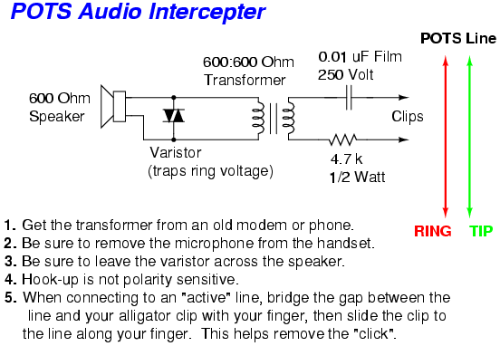
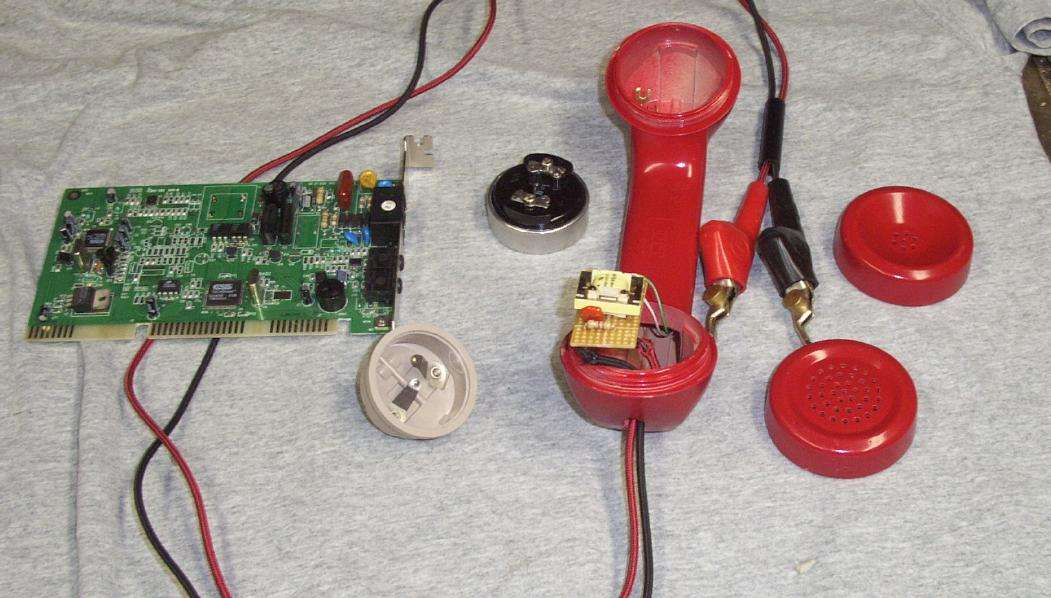
Picture of the POTS Audio Interceptor. The coupling transformer is from an old modem.

Closeup view.