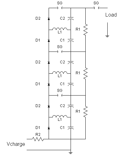
There's an error in this drawing.. there should not be a short from R2 to ground.
The Fitch circuit is used when better control of the impulse voltage is required than can be provided by the Marx circuit.

There's an error in this drawing.. there should not be a short from R2 to ground.
Let's just consider a couple of stages.
ChargingDuring charging, the capacitors charge through D1 and L1. Current passes to the next stage through D2. The polarity of the voltages on C1 and C2 are reversed, so there is no net voltage on the two. Ia is the charging current throug D1, L, and C1. Ib is the charging current through D1, L, C2, and R2. Ic is the charging current through D1, D2, D1 (in the second stage), L(second stage), and C1(second stage). And so forth. |
|
Now we are charged and ready to fire.
Erection, phase 1Now, we trigger the gaps, so current starts to flow in the resonant circuit C2, L1, D2, SG, shown by loop ILC. D1 is reverse biased during this time: C1, L, D1, SG. |
 |
Erection, phase 2A half period later, the voltage on C2 is entirely reversed, but it cannot discharge, because D2 would be reverse biased. The spark gap extinguishes. C1 and C2 are now in series with the same polarity, so the stage voltage is twice the original charge voltage. The fall time is set by the resistance of R2 |
 |
L must be able to store all the energy in C2 in this circuit. One would also want to keep the loop current high enough that the spark gap stays "ignited" (on the order of 4-5 Amps), but low enough that the diode D2 doesn't disappear in a puff of smoke. Most diodes, though, have a Ipk substantially higher (10-20 times) than their continuous rating (1N400x series of 1Amp diodes have an IFSM of 30A, 1N540x (3Amp) series has IFSM of 200A).
Say we have a stage voltage of 50 kV, and 1 uF capacitors (i.e. a stored energy of 1.25 kJ). We want to keep the peak current below 150A (we're using some form of 3Amp diodes..), and since E=0.5 L I^2, we can calculate the inductance as L = 2500/(150*150) or 0.11 Henry, which seems quite high...
Perhaps, if one used much smaller capacitors... 10 nF, for example. Then, the inductance would be 1.1 mH, which, although high, would start to be more practical. In this case, the half period ( 2*pi*sqrt(L*C2)) would be about 20 microseconds.
One would probably want erection times substantially less than a microsecond, though, so a more reasonable inductance would be even smaller, although, that will raise the peak diode current.
Bazelyan and Raizer, Spark Discharge, pp 97-98
Copyright 1998, Jim Lux / fitch.htm / 22 August 2002 / Back to HV Home / Back to home page / Mail to Jim