The required grounding for a tesla coil is the subject of much discussion, theorizing, and commotion. This page describes the various factors and things to consider.
There are three basic kinds of grounding to contemplate in respect of a tesla coil:
The first one is essentially a "don't burn down the building" and "don't electrocute the user" sort of ground, and the second two are more concerned with the "performance" of the tesla coil. However, we need to consider both, because they DO interact, and are often connected together.
Electrical Safety Ground (i.e. the "green wire" ground) designed to make sure that a presumably grounded person won't get hurt if they touch some part of the chassis. The safety ground is also to make sure that if there is an internal short from the AC power line to the chassis, that a fault current will flow, tripping the breaker or blowing a fuse, rather than making the outside case (i.e. what a person might touch) "hot".
Another approach to this function is to "double insulate", a strategy that is widely used on AC powered appliances (VCRs, TVs, etc.). Here the philosophy is that if there are two "stages" of insulation between the AC line and the case, if one stage fails, the case is still isolated from the AC line, and won't float hot.
What to watch out for: Stray capacitance from line to case.
Considerations for the HV secondary. In many tesla coil circuits (particularly those using Neon Sign Transformers), the HV transformer secondary is connected to the chassis or core of the transformer. This is done to reduce the peak voltage stress between the secondary winding and the core. However, this now means that the secondary is not insulated/isolated from ground.
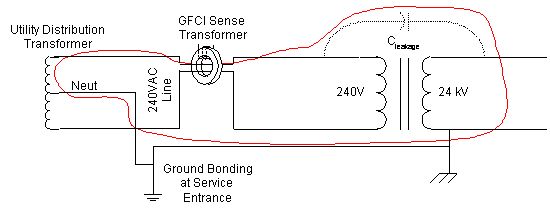
Stray capacitance that would be of negligible concern at 120 or 240V is now a significant problem. Consider a stray capacitance of 100 pF. At 60 Hz, the impedance is 26 Megohm. At 240V, you'd get only 9 microAmp of leakage current. However, at 24 kV, the story is a bit different, because you'll get 0.9 mA, which something you can definitely feel, and may be enough to trip a GFCI. Let's look at the circuit for this last case. The red line traces the leakage current path.

What you don't want on the safety ground: RF
You don't want any significant RF current to flow over the safety ground wire for a number of reasons. First is a philosophical objection: The safety ground is to carry fault currents, ONLY, and shouldn't be used as an intentional circuit conductor. A more practical reason is that a lot of things are connected to that safety ground wire (like VCRs, computers, appliances, etc.). If you put significant RF current through the safety ground, then there will be significant RF voltages in the system. The typical RF bypass circuitry in consumer equipment is designed to deal with millivolts, not tens of volts. So, how does RF get onto the safety ground?

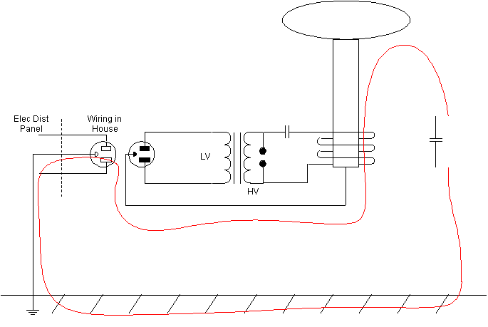
This figure shows a typical tesla coil circuit. The TC secondary circuit is composed of the inductance of the secondary in series with the capacitance of the secondary. That capacitance is the "topload" and the "self C" of the secondary, but, what's usually not stated is that the capacitance is with reference to the ground. There is some capacitance from the topload to the bottom of the secondary winding. This sort of C is what makes a bare coil of wire have a self-resonant frequency, but, for most TCs, there is significant capacitance from the topload to the ground under the coil (i.e. the floor).
The fact that there may be 100 feet of wire from the tesla coil, through the wall socket, back to the electrical panel, and then to a ground rod, doesn't make a huge difference. At 100 kHz, that's still a small fraction of a wavelength (100 kHz = 3000 meter wavelength), the DC resistance is only a tenth of an ohm or so, and skin effect makes the resistance maybe 2 or 3 times that. However, one would want to worry about the resistance of all the connections along the way, and what effect the capacitance from the ground wire to surrounding metal objects might have.
(just for an example, what might the typical RF current be? Assuming a 1200 Watt input, and 120 bangs/second, each bang is 10 Joules. For a tesla coil 4" in diameter, 20" long secondary, wound with AWG24, the Lsec is around 13.4 mH, Cself is 9.3 pF, Ctop would be around 37 pF, for a resonant frequency very close to 200 kHz.
hv/tcground.htm - 19 March 2003 - Jim Lux
(hv index) (Jim's
home page)