Overview
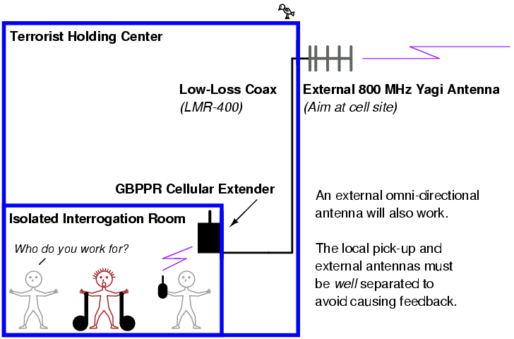
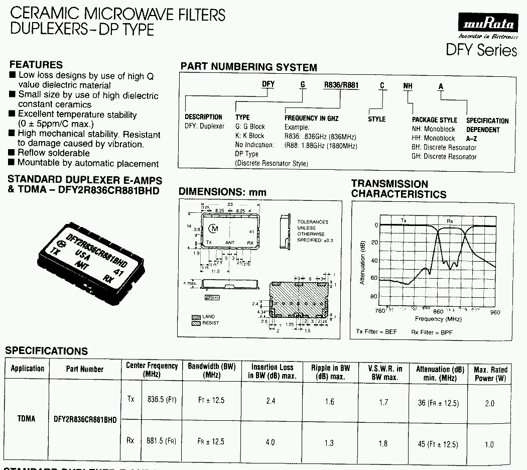
The GBPPR Celluar Extender is an experimental hardware device to extend the coverage area for any cellular phone operating in the 800 MHz band. It is useful for providing cellular phone service to shielded or isolated locations. Cellular extenders work by capturing and amplifying the radio signals as they travel in both directions. The operation is very similar to a regular ham radio or C.B. linear amplifier, except there is no need for any transmit/receive switching. Since cellular phones operating the in 800 MHz band are offset by 45 MHz (825-850 MHz handset transmit, 870-895 MHz handset receive), the high isolation needed for the separate transmit and receive amplifier paths can be accomplished using salvaged duplex antenna filters from old cellular phones. These duplex filters are designed to highly isolate the transmit and receive ports using a series of high-pass & low-pass tuned filters, and also provide a common 50-ohm port for the antenna.
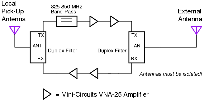
When two of these duplex filters are used, and amplifiers are placed between the two ports, one can easily amplify each of the separate transmit and receive frequencies. Commercial devices utilize lots of gain, up to 50 dB, and with transmit output powers hitting +30 to +33 dBm (1 to 2 Watts). This particular device will have a much lower output RF power because it's still an experimental device. Lower RF output power devices are much easier to operate and construct, and technically, you'd need some sort of automatic power level control circuit to make the Failed Clown College boys happy. That ain't gonna happen. Also, this device, as constructed, will not function with Motorola iDEN, Nextel, or other conventional 800 MHz radio systems.
How it Works & Operation
Excerpt from: Wireless Extenders Model YX500-PCS Cell Phone Signal Booster
Theory of Operation
Note: This covers a PCS version operating in the 1.9 GHz cellular band.
As a bi-directional amplifier, the YX500-PCS amplifies both the downlink (tower to phone, 1930-1990 MHz) and the uplink (phone to tower, 1850-1910 MHz). The outdoor network signal (downlink) is captured by the Signal Antenna, transferred through the coaxial cable, and arrives at the Base Unit. Inside the Base Unit, a duplexer diverts the downlink signal, amplifies the full band, isolates it from the uplink, and detects the power level. The downlink band is then recombined with another duplexer where the Base Unit Antenna sends the signal inside the home or office. Similarly, the cell phone signal (uplink) is captured by the Base Unit Antenna and, inside the Base Unit, a duplexer diverts the uplink signal, amplifies the full band, isolates it from the downlink, and detects the power level. The uplink band is then recombined with another duplexer where it exits the Base Unit, is transferred through the coaxial cable to the Signal Antenna which sends the signal to the outdoor network. The detected power levels are monitored by a microcontroller. The microcontroller limits the maximum output power to keep the amplifiers linear without interfering with the network power control. It also detects low-level self-oscillation and either corrects it or alerts the user with LED outputs.
Block Diagrams
Pictures
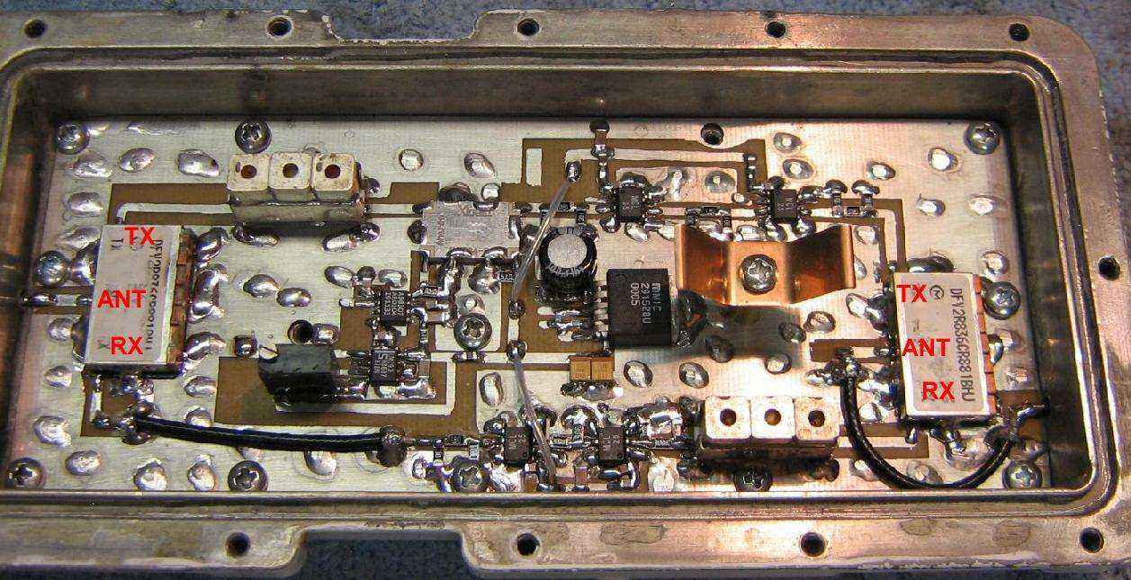
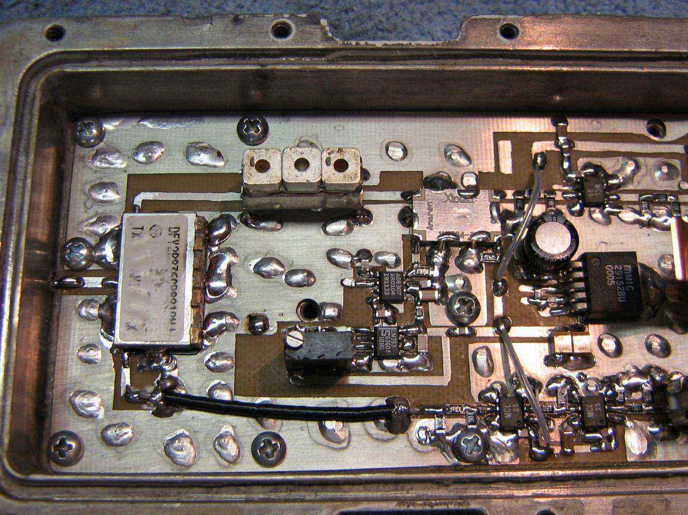
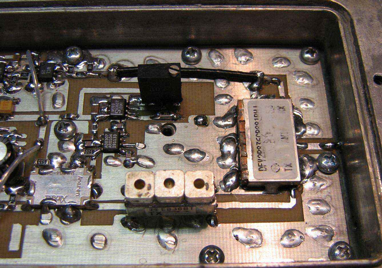
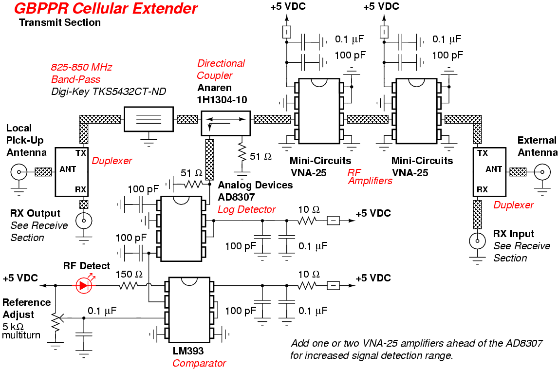
Overview of the GBPPR Celluar Extender. There is a reason it looks like it was built over a weekend... Local pick-up antenna input is on the left. It then passes onto a salvaged Murata DFY2R836CR881BHJ duplex filter. The Transmit Path (825-850 MHz) is on the top left. It then passes through a salvaged Toko 6DFB-836E-10 (or equiv.) 3-pole band-pass filter and onto a Anaren 10 dB directional coupler. The directional coupler samples the input RF and passes it onto an Analog Devices AD8307 logarithmic detector and LM393 comparator. This should light an LED when receiving any RF input. After the directional coupler, the signal is amplified by two Mini-Circuits VNA-25 MMIC amplifiers and then finally onto the output duplex filter. The external antenna input is on the right.
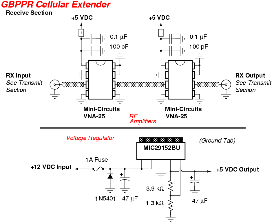
The Receive Path (870-895 MHz) is along the bottom. The signal comes in the external antenna input on the right, passes through a salvaged Toko 6DFB-881E-10 (or equiv.) 3-pole band-pass filter (which is optional, as the duplex filter acts as a band-pass filter on the receive port), and is also amplified by two Mini-Circuits VNA-25 MMIC amplifiers. Its finally output to the local pick-up antenna on the left.
The particular amplifier shown in these photos has 3 dB resistive attenuator pads on all the VNA-25's inputs and outputs. This was done to prevent the amplifiers from breaking into oscillation. You'd need access to good RF test equipment to detect and cure this. The attenuator pads can be eliminated if all the RF paths maintain a perfect 50 ohms impedance.
Also, placing a VNA-25 (or two) amplifier ahead of the AD8307 will help to increase the signal detect range for lighting the LED.
Digi-Key sells a AMPS Duplexer Surface Mount Ceramic Filter, if you can't find some in old cell phones. Part number 410-1022-1-ND for $28.
Commerical cellular extenders often use a RF Micro Devices RF3108 triple-band amplifier module for the final power amplifier on both the 800 MHz and 1.9 GHz bands. Mini-Circuits MNA-5s are used as the gain stages.
Also, two back-to-back directional (Yagi) UHF TV antennas will work as a "passive repeater." Point one towards the cellular site an d one towards the "problem" area. Connect them with a short piece of RG-6 coax.
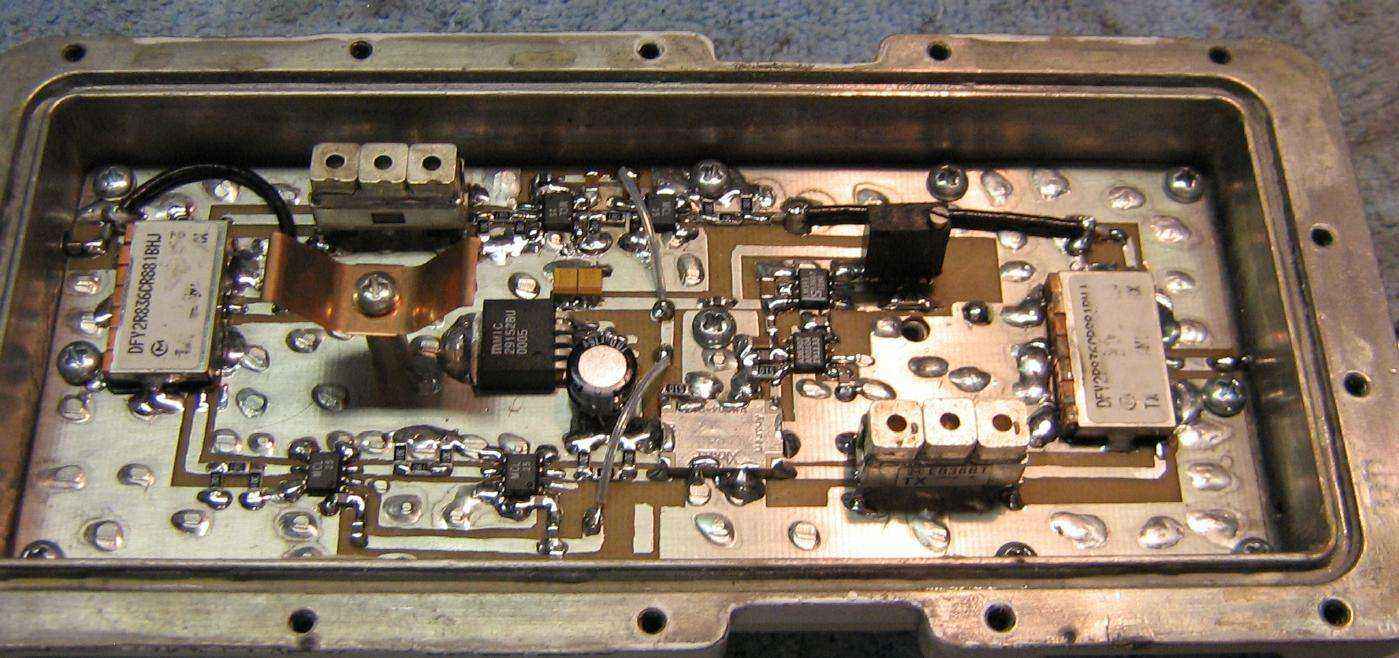
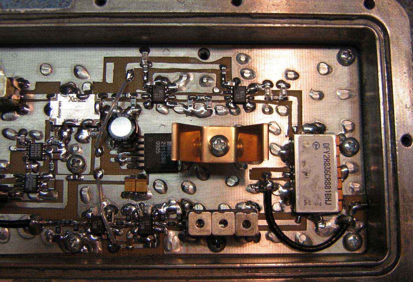
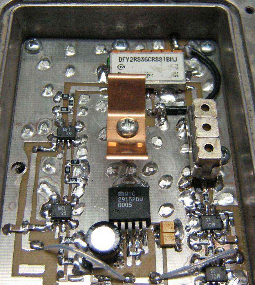
Rotated view. A Micrel MIC29152 (center) provides the +5 VDC voltage regulation for the entire circuit. The black multiturn potentiometer sets the reference voltage for the LM393 comparator. When the AD8307 logarithmic detector receives a strong enough RF input signal, its voltage output will exceed the reference voltage. A red LED is then lit as a "RF Detect" indicator.
Close up of the local pick-up antenna side.
Close up of the external antenna side. The external antenna needs a large amount of free-space isolation to avoid feeding back into the local pick-up antenna. You might have to experiment a bit to get everything working. One commerical cellular extender recommends separating the antennas by at least 16 feet, with 8 feet of vertical separation. This corresponds to over 50 dB of free-space isolation.
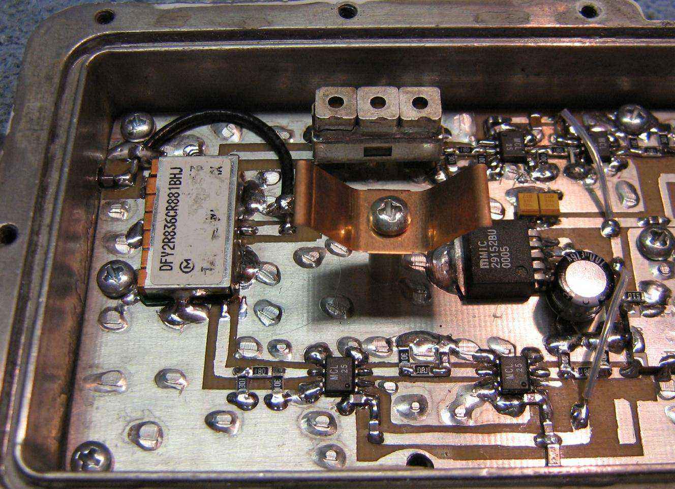
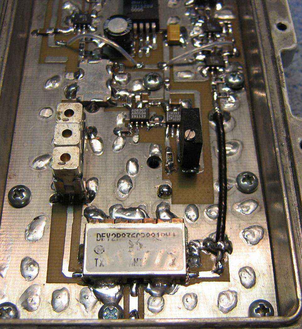
Alternate view. External antenna side.
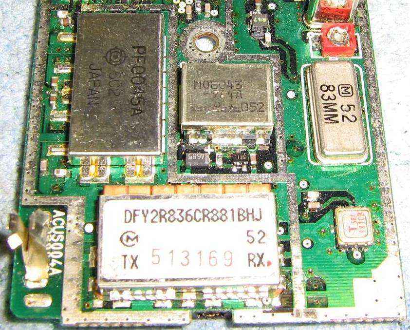
Picture of a Murata duplex filter installed in an old cellular phone (don't remember the model).
Alternate view. Local pick-up antenna side.
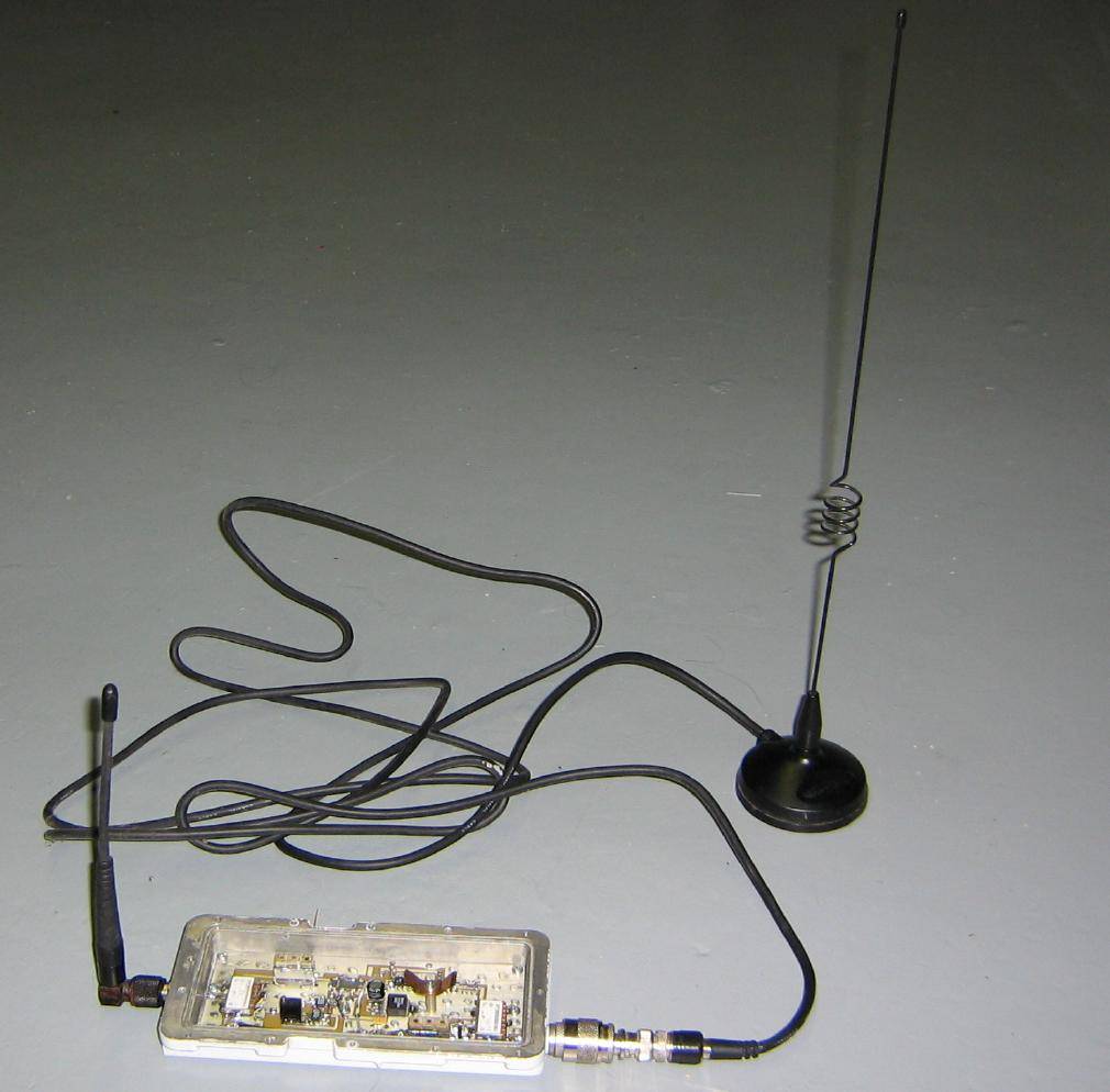
Example of the GBPPR Celluar Extender using a rubber duck local pick-up antenna and a mag-mount cellular antenna.
Another view. Transmit side is on the left, receive side is on the right. "Real world" models should have a bit of copper shielding to further isolate the two sides.
Another view. Local pick-up antenna port on the bottom, transmit on the left, receive on the right.
Schematics
- GBPPR Cellular Extender - Schematic #1 Transmit Stage
- GBPPR Cellular Extender - Schematic #2 Receive Stage / Voltage Regulator
Datasheets & Notes
- Higher resolution pictures and the original project article are available in GBPPR 'Zine Issue #25
- Murata Cellular Duplexer Information
- Mini-Circuits VNA25 MMIC Amplifier (55k PDF)
- Micrel MIC29152 Positive Voltage Regulator (148k PDF)