Overview
This is a simple, and portable, over-the-air television station made from some components and video modules which were found in a local cable TV company's dumpster. The heart of the television station is based around a Holland Electronics HM55 Audio/Video Modulator. This is the device the cable TV company uses in their "head-end" to generate the TV signal which is eventually distributed throughout their coaxial cable network. This particular model HM55 modulator is set to transmit on CATV channel 8 (180-186 MHz). This frequency also happens to correspond to over-the-air TV channel 8. You should also try to find a modulator which transmits on standard over-the-air, VHF middle-band frequencies. The VHF-mid band allows for the use of physically smaller antennas, better overall RF coverage, and the option of using converted amateur radio or two-way radio RF power amplifiers and test equipment. Avoid the 55-88 MHz VHF low-band (TV channels 2, 3, 4, 5, & 6), if you can, and the 470-880 MHz UHF frequencies (TV channels 14-83). UHF frequencies attenuate much faster than lower frequencies, and everything tends to be much more "fussy" at those higher frequencies. Chances are you won't be able to find the exact same components as used in this project, but similar models do appear on eBay from time-to-time.
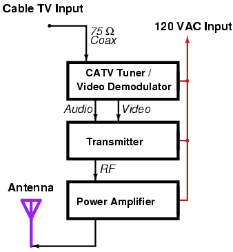
What this project does, basically, is to use a standard cable TV tuner module to demodulate the cable TV company's audio and video signals, then rebroadcasts those same audio and video signals at a frequency which a normal TV can receive. This allows others in your neighborhood or surrounding area to watch your favorite cable TV channels without having to pay $50 a month! Isn't that nice? The transmitter's video input signal doesn't have to be from a cable TV tuner module. It can be any standard NTSC video signal source such as VCRs, DVDs, camcorders, video games, etc. The use of a 1.2 GHz or 2.4 GHz amateur radio television link can be adapted for use as a poor man's Studio-to-Transmitter (STL) link. Broadcasing porno videos around your neighborhood is not recommended.
An old cable TV "bridger" hybrid amplifier module is used to amplify the final RF signal generated by the Holland video modulator up to a more reasonable output power level. These amplifiers are what you'll find inside those little silver boxes hanging from the overhead coaxial lines up on the poles. Your local cable TV company's dumpster should have a few working, or easily fixed non-working ones, inside it. Check often, or just ask them. Grab some 75 ohm hardline scraps and connectors for your scanner radio runs while your at it, also. The amplifier module will require around +24 to +28 VDC at around 500 mA. The voltage polarity usually isn't marked on the amplifier's case, so be careful and reverse engineer the connections out ahead of time. There may be two or more potentiometers accessible from the outside of the amplifier module's case. If one is marked "slope," leave it alone. If one is marked "gain," then crank that puppy up! Don't expect to get more than 800 mW of RF power out of a single hybrid amplifier module. A few of them will hit two watts (+33 dBm) will a little tweaking. Consult standard VHF class-A linear amplifier schematics and application notes if you want any more RF output power (you will). TV RF power amplifiers need to be linearly biased to pass all the synchronization signals without any distortion. Non-linear class-C or class-AB amplifiers, like those found in some two-way radios, can be used in a pinch, but the resulting video picture will look like crap, if the television is even able to lock onto it. Experiment around. Non-linear amplifiers can, however, be used to amplify just the audio carrier section of the television signal, which can be also be quite useful.
The radiating antenna will be nothing more than a slightly tweaked set of rabbit ears and a common 300-to-75 ohm impedance matching transformer. Transmitted television signals are normally horizontally polarized, but for portable emergency operations, vertical polarization may be better. Anyone watching on one of those cheap $20 portable TV sets will most likely have their antenna raised vertically.
The main hardware components will be mounted within a small homebrew 19-inch rack carrier made from common 3/4-inch square aluminum tubing and L-brackets. View the constuction pictures for more information on how to build the overall structure. It doesn't have to be the same, but try to keep it portable, if needed.
Block Diagram
Construction & Pictures
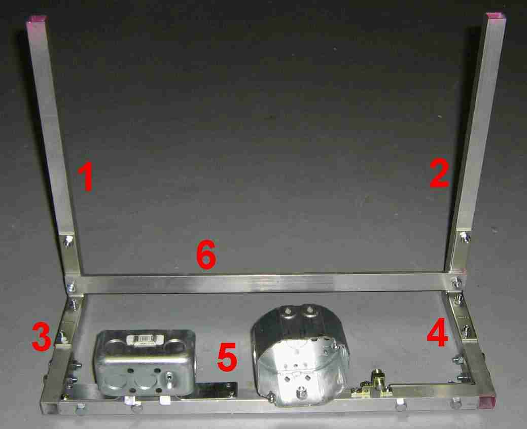
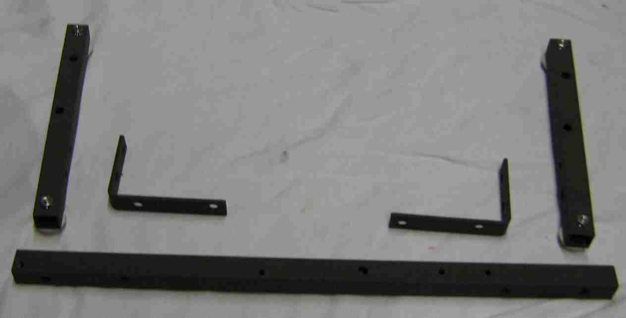
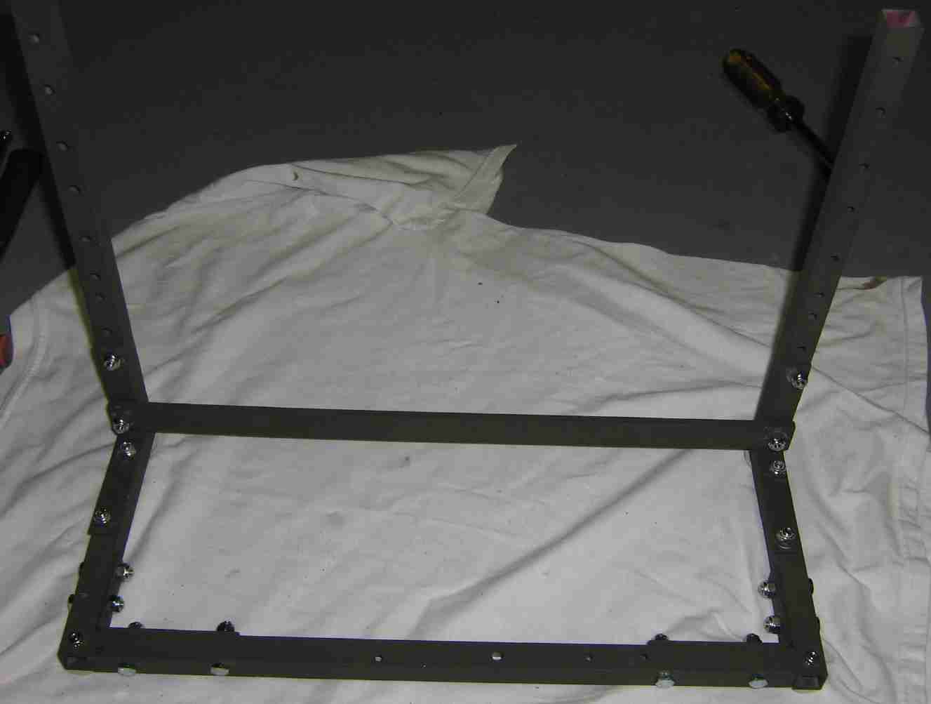
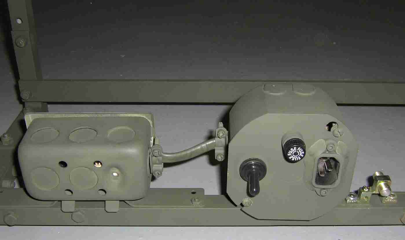
Prototype and testing setup. It is made from two pieces of three foot long, 3/4-inch square aluminum tubing, four 4-inch long by 3/4-inch wide L-brackets, a single 19-inch piece of 1-inch wide by 1/4-inch thick aluminum bar stock (#6 across the bottom), and assorted 1/4-inch bolts, nuts, washers, etc. A metal outlet and octagon box are for the 120 VAC input, power switch, and filtering. The CATV coax input is via a standard ground block.
Cutting Chart
Piece #    Length (inches)
-------    ---------------

1          13.5
2          13.5
3           8.0
4           8.0
5          17.5
6          19.0
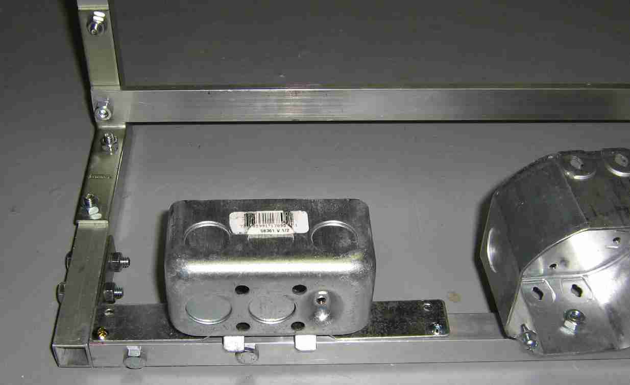
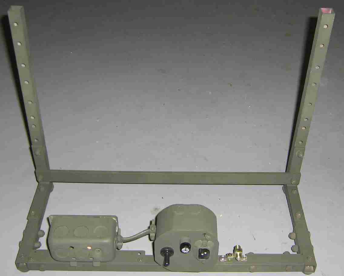
Close up of the rear side, near the outlet box. If you look closely, you'll notice the inside L-bracket had to be cut down a little to fit.
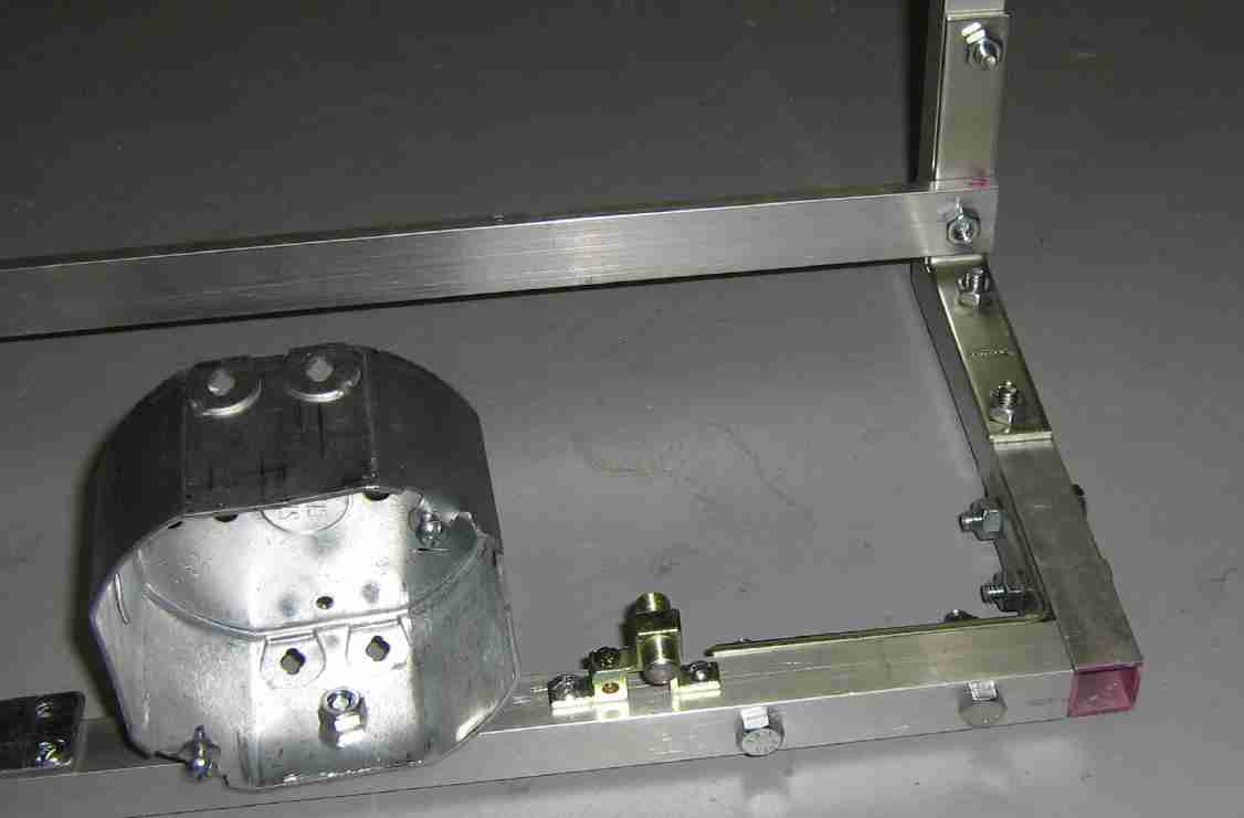
Other side, rear view showing the octagon box and the CATV grounding block.
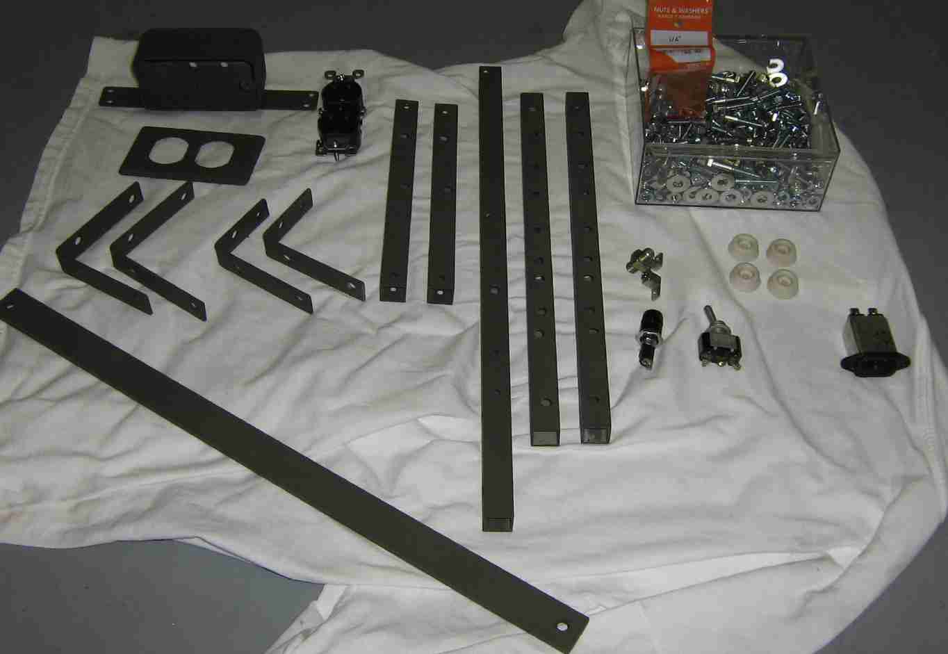
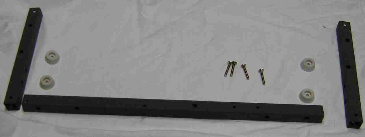
All the parts are disconnected, cleaned, and spray painted camo green. The hardware shown on the right side: assorted 1/4-inch hardware, CATV ground block, four rubber feet, fuse holder, power switch, and an AC input filter. The top left shows the parts for the filtered AC outlet.
Assembly of the rear section. Four holes and rubber feet were added to prevent the scratching of any surfaces. Swap out the stock rubber feet hardware for some 1-1/4 inch long, #8-32 "stove head" bolts. Those are the ones with the big, flat heads.
Rubber feet added. Rear L-brackets are next. Note how I had to cut one side of them down to fit (they hit the bolts on the top bracket). This is because I'm a retard and didn't think anything out ahead of time. You'll need to cut and redrill them, or extend the length of the side pieces.
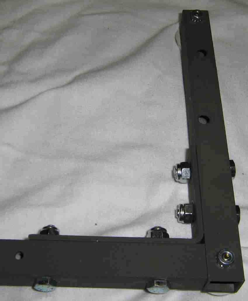
Close up view of a rear corner showing how the assembly hardware should fit.
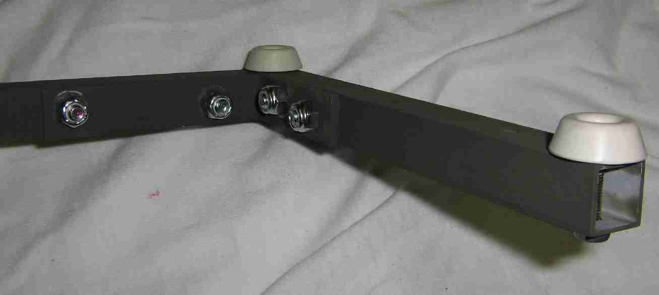
Bottom view of the above piece showing the rubber feet.
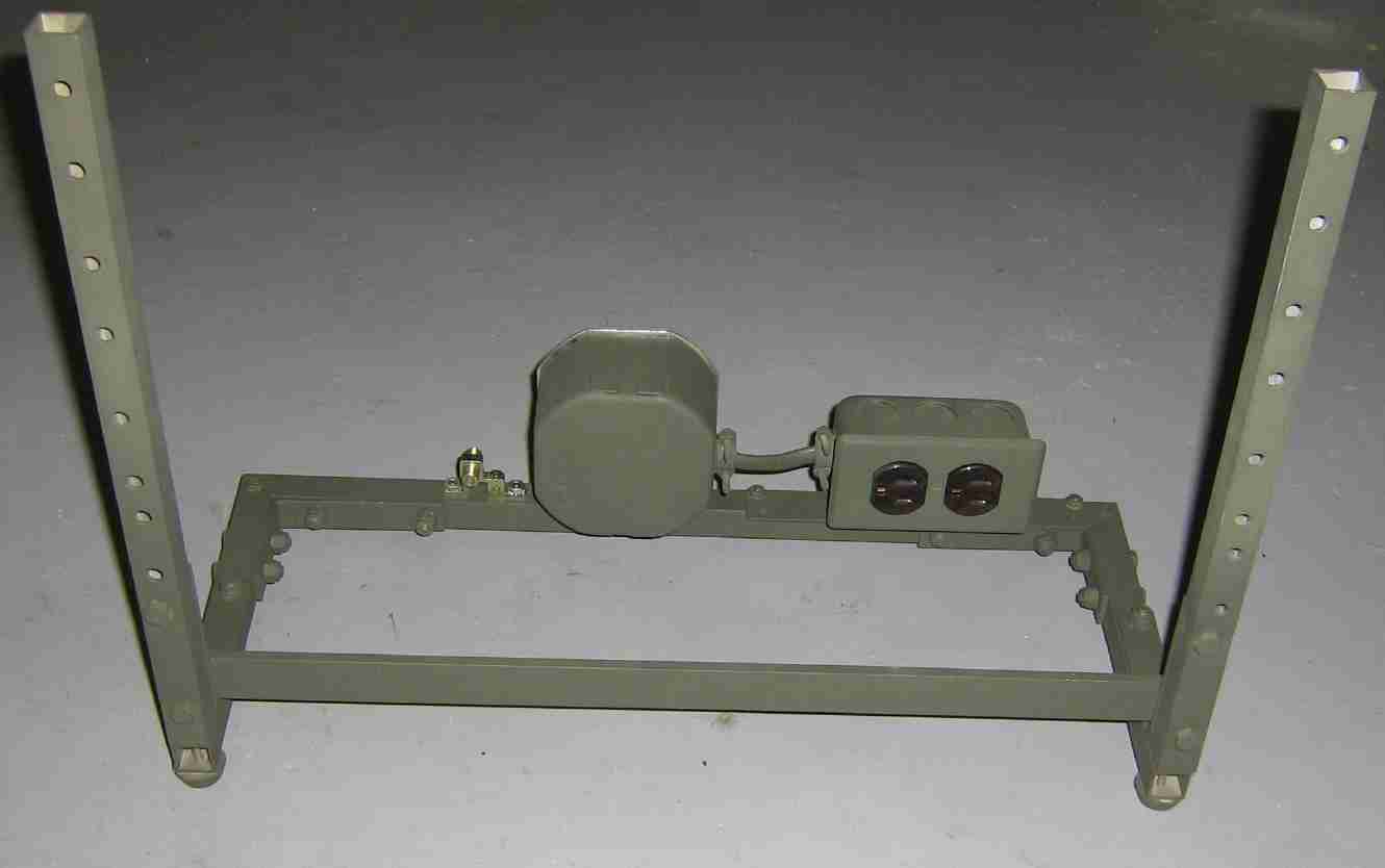
Overview of the completed frame.
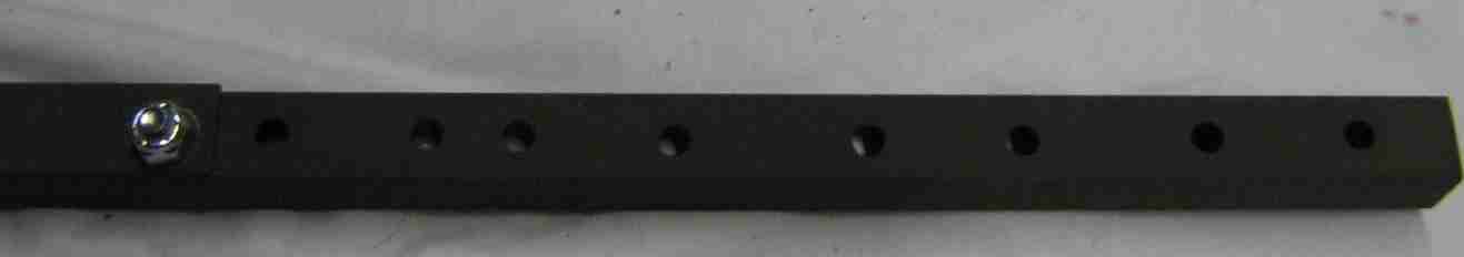
Close up of a corner. The bottom support bar should match up with the bottom hole in the L-bracket. You'll need to use slightly longer hardware to attach the support bar.
Holes drilled for the 19-inch wide rack mounted hardware. There should be an one inch gap between each module. It's best to "line up" the rack mounted hardware by hand, then drill the holes. There is an extra set of holes for any emergency modules.
AC power outlets added. Standard wiring setup, the AC comes in through the filtered outlet, through a SPDT switch, and then through a fuse holder (3 Amp fuse). It's then sent out to a standard dual-ganged AC outlet. If you can't figure any of that out, stop reading $2600 Magazine.
Alternate view.
Close up view.
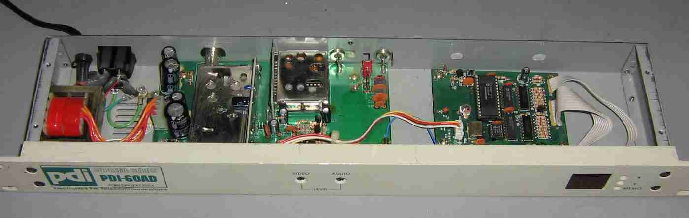
Component module number one. PDI Communications PDI-60AD Frequency Agile Audio/Video Demodulator. This takes the CATV input and demodulates the audio and video. It's just like a fancy VCR or TV tuner, only in a 19-inch rack. More information is available here: http://www.pdi-eft.com/htmlandflash/proprietary/60ad.html
No modifications were done to this device, except for taping over some of the holes to help waterproof it a bit.
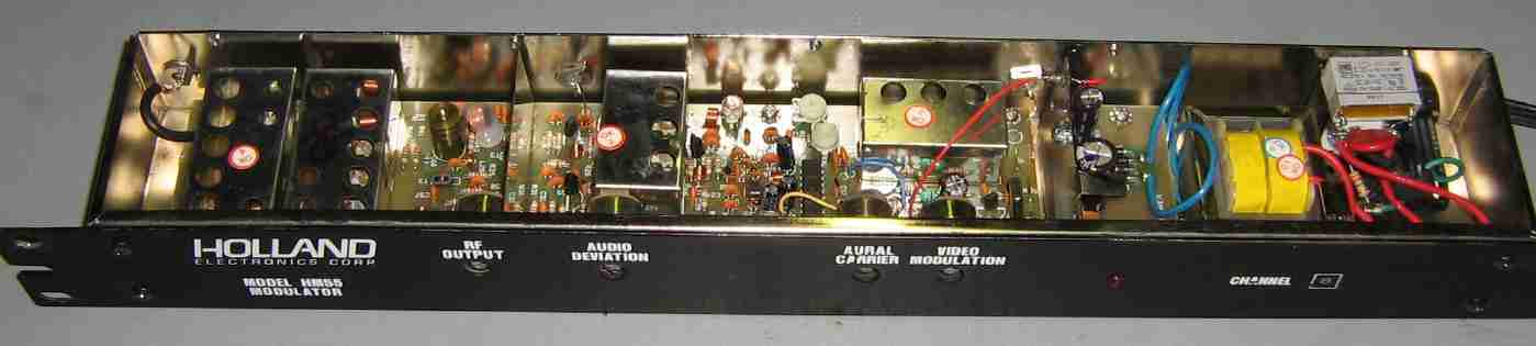
Component module number two and the heart of the rebroadcaster. Holland HM55 Modulator. You'll want to raid your local cable TV company's dumpster for this device, or search really hard on eBay. On eBay, they vary from $9 to $50. There is one major problem. They are frequency fixed. Try to get ahold of a modulator which isn't tuned for a local TV station which is already on the air. This usually isn't a problem, but it could be in some "frequency saturated" cities. The particular Holland HM55 shown here is tuned for CATV channel 8, which also happens to correspond with over-the-air TV channel 8. Internally, it has a zillion different potentiometers and trimmer capacitors. Yes, I messed with all of them. I have no idea how to tune a TV transmitter, so just play with it until the picture looks pretty.
Now, another problem - if you get your modulator from a dumpster - is that there is probably something wrong with it. Most likely, the power supply inside the modulator is fried (or failing) and 60 Hz hum is interfering with the audio or video signals. That was the problem with this particular module. The electrolytic filter capacitors where dried out. Thankfully, it was trivial to repair the power supply section, as it's a simple step-down transformer and bridge rectifier feeding a LM7812 voltage regulator. Replace the old electrolytic capacitors with new ones of similar value.
Here are the Holland HM55 modulator's specifications from someone's old eBay page: http://ruarto.com/ebay/hm55.html
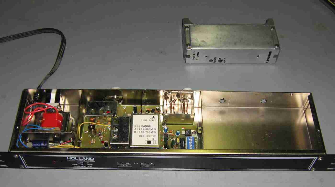
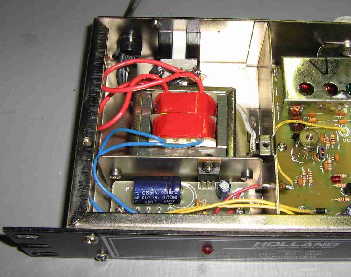
Component module number three. This consists of a "bridger" CATV hybrid amplifier mounted inside an old Holland UHF-to-VHF cable TV converter 19-inch rack case. Only the power supply, +18 VDC here, is used from the converter's case. Most CATV hybrid amplifiers require +24 or +28 VDC at around 500 mA to operate. This one appeared to work fine at only +18 VDC. The nice open space inside the case is a good place to mount the new RF power amplifier. Two new holes for the RF input and output should be drilled.
Power supply from the UHF-to-VHF cable TV converter. It's based around a standard LM7818 voltage regulator. The input electrolytic filter capacitor should be beefed up a bit.
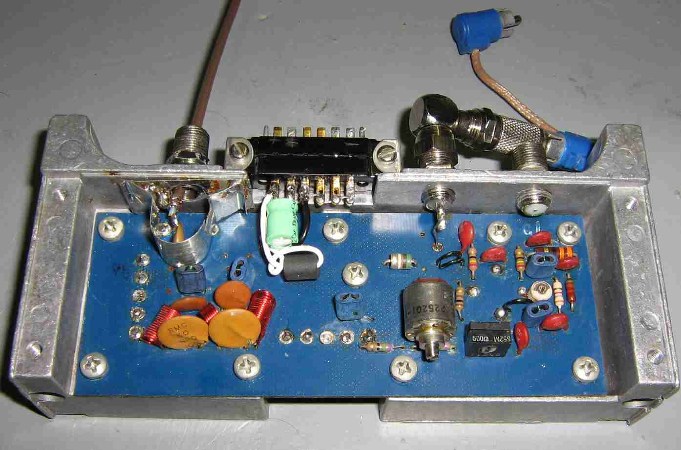
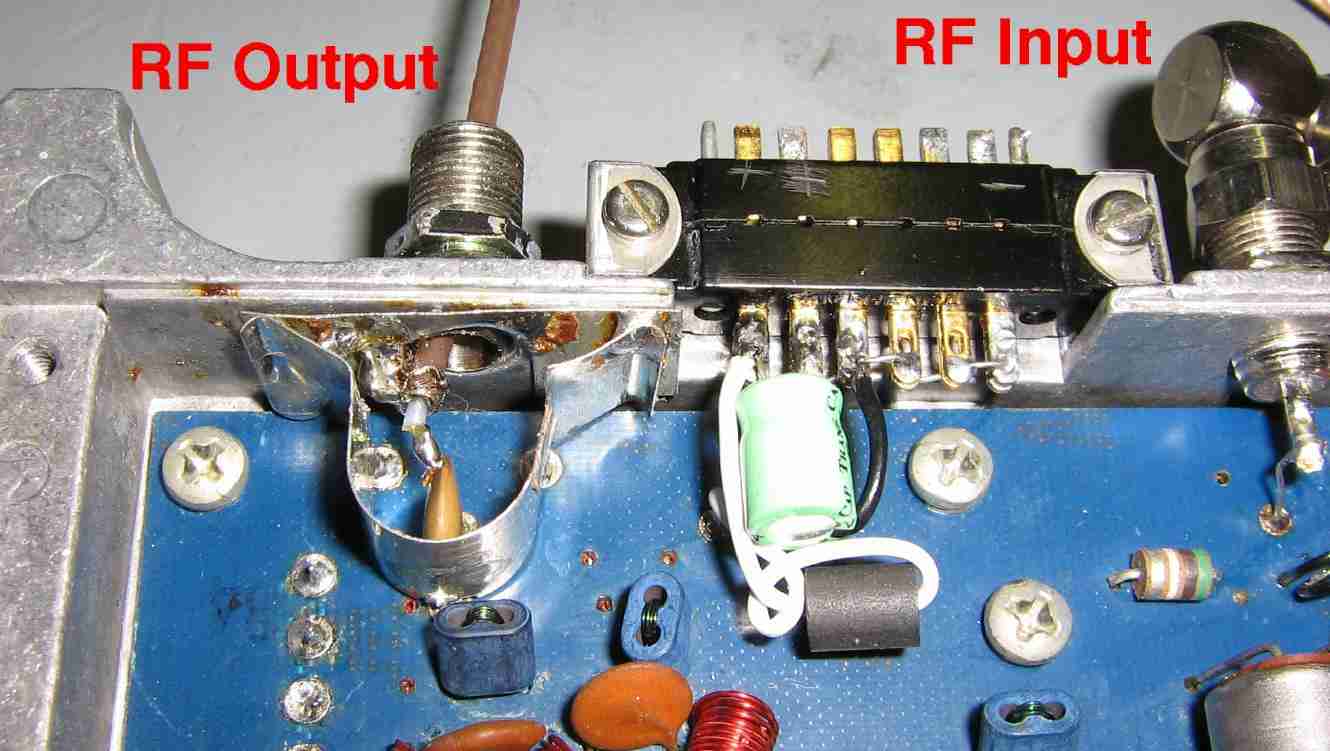
Inside of the bridger hybrid amplifier module. The only modifications were adding a new electrolytic filter capacitor and ferrite bead on the postive voltage input lead, adding some new RF input F-connnectors on the right side, and taping the RF output using a piece of coax instead of using the stock F-connector.
RF output connection closeup.
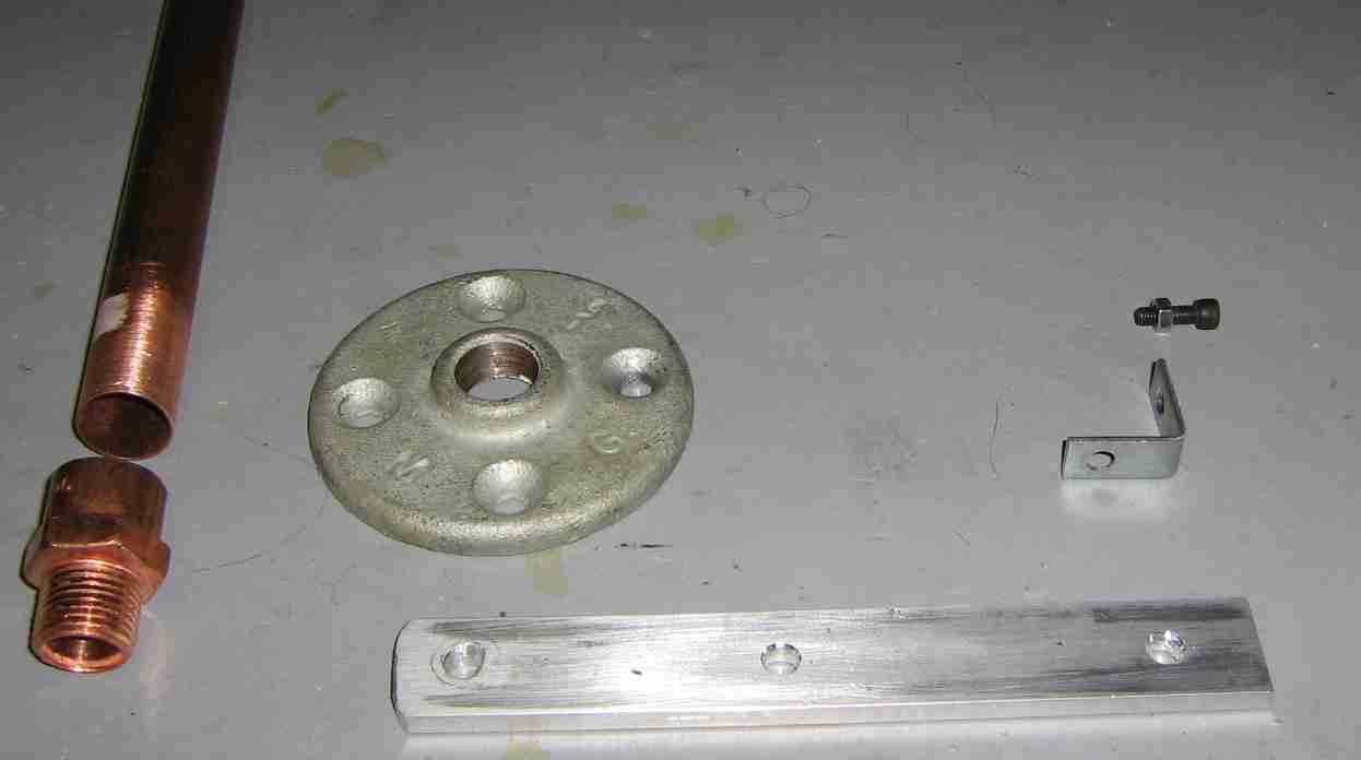
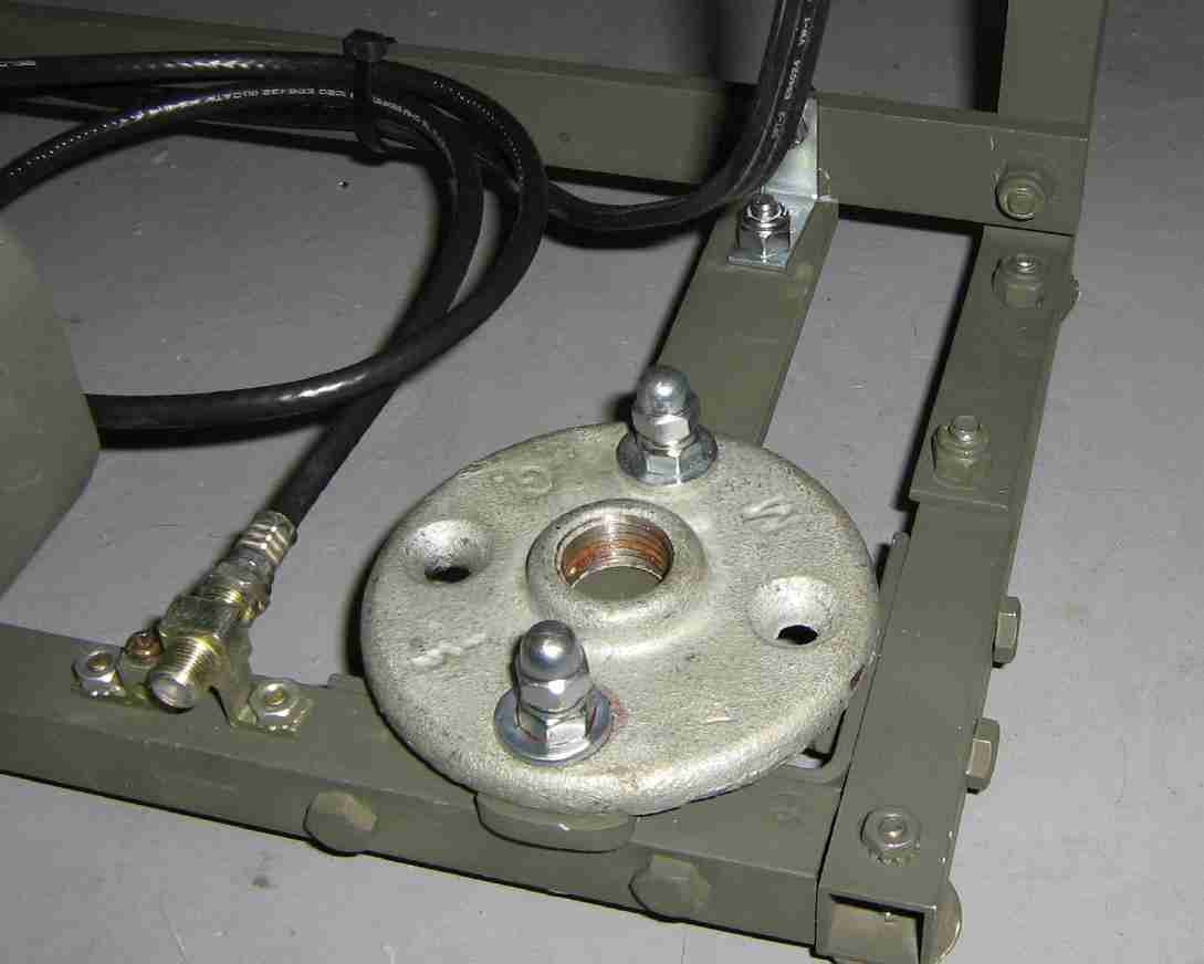
A simple removable antenna mount is made from 3/4-inch copper pipe (and threaded screw fittings), an iron pipe floor plate thingy, a short piece of 1-inch wide aluminum stock, a single 1/2-inch L-bracket, and assorted hardware.
Put it together like this. It actually works out quite well. Not having the antenna sticking out the side really saves on space. Put a bit of grease on the copper pipe threads to prevent them from being damaged.
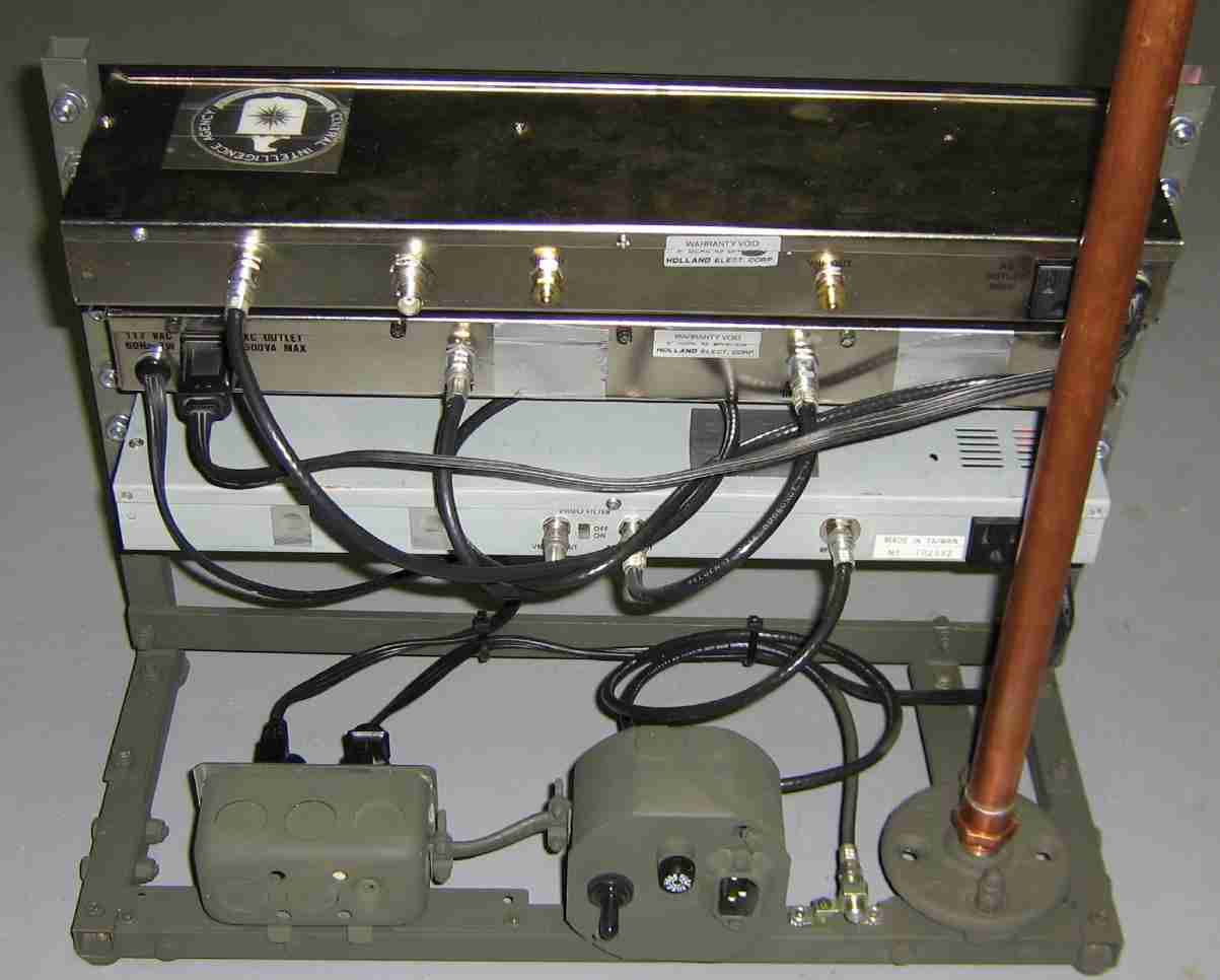
Everything is put together!
Rear view.
Front view.
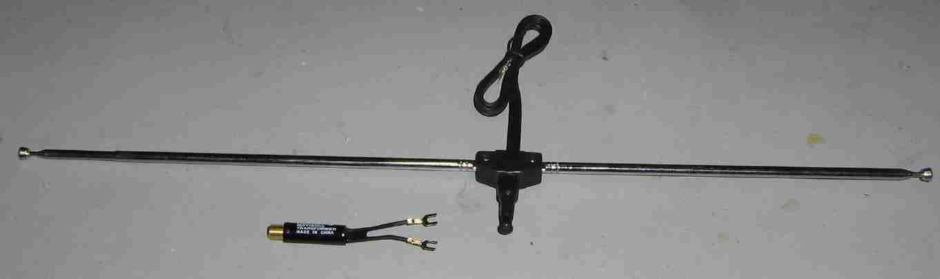
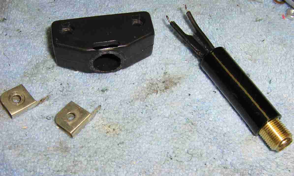
The transmitting antenna will be made from an old set of adjustable rabbit ears, and a common 300-to-75 ohm matching transformer. The input RF power will need to be kept quite low (under 1 watt) to avoid saturating the ferrite core in the matching transformer.
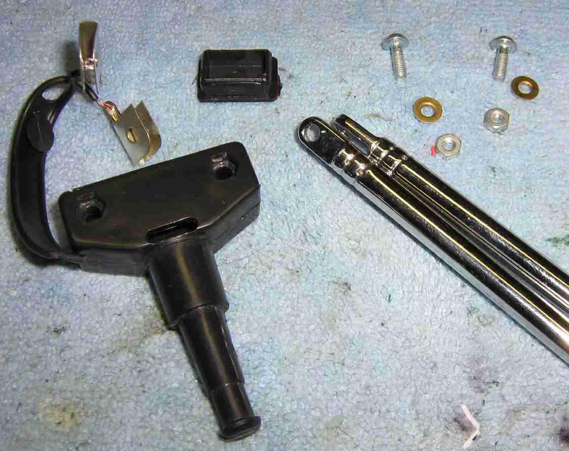
Taking the antenna apart. Be sure to do this very carefully. Note the little brass washers which couple to the actual antenna elements.
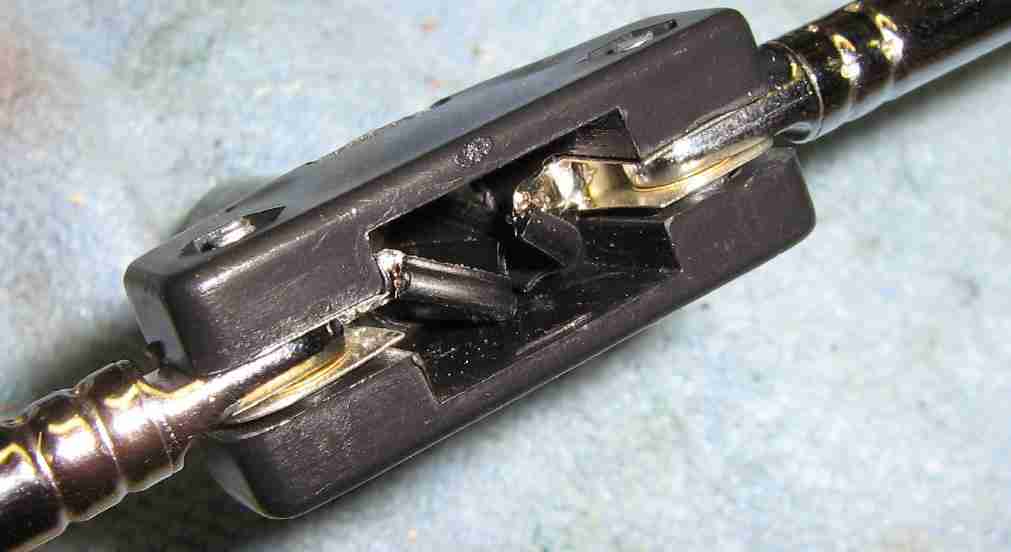
Trim the plastic case to the antenna to match the diameter of the impedance matching transformer. Also slightly trim down the 300 ohm leads on the transformer.
Solder the transformer's leads to the antenna element clips, and carefully put everything back together.
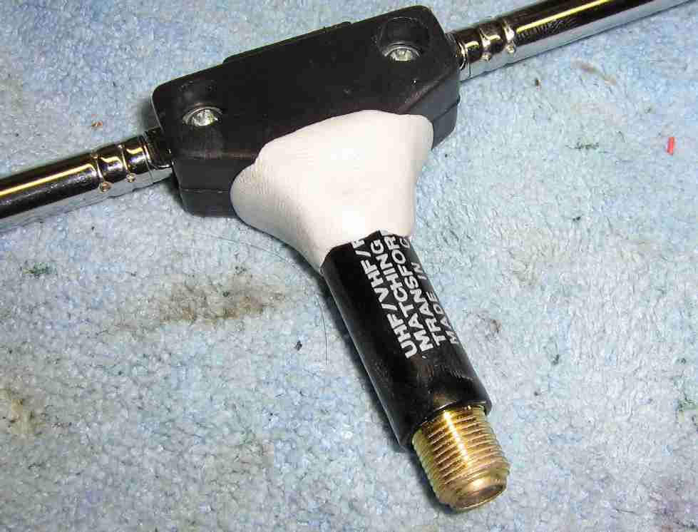
It should look something like this.
Use some two-part epoxy putty to secure the matching transformer to the antenna's body.
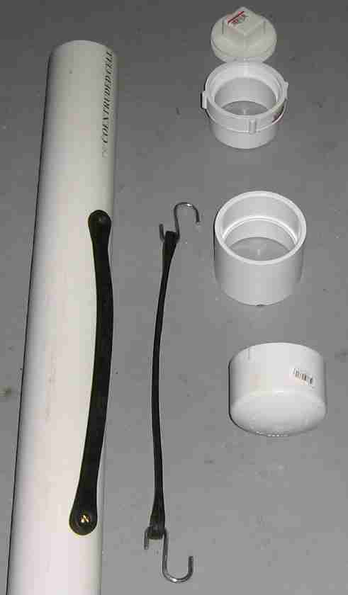
Drill a 15/32-inch hole (down about twelve inches to protect the antenna elements) in a three foot long piece of 1/2-inch diameter PVC pipe. You'll then epoxy the entire matching transformer/antenna assembly onto the PVC pipe. Also, add a threaded coupler to the bottom end of the PVC pipe to mate to the threaded coupler on the lower copper support pipe.
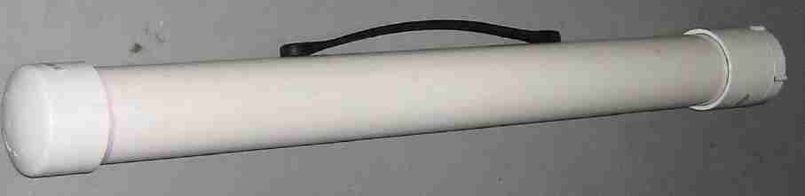
An optional antenna system carrier made from PVC parts. A length of 3-inch diameter PVC pipe (slightly longer than three feet) has mounted on one end a cap, and on the other end, a 3-inch coupler and threaded "clean out" cap. Make a handle out of a rubber bungee cord (with the hooks removed) bolted onto the PVC pipe. Pack in some sponges to keep everything from rattling.
Completed PVC antenna mast carrier. It is also a good idea to include some other helpful items inside the carrier like a multitool, some duct tape, a short length of rope, various RF adapters and connectors, AC power cord, coax jumpers, etc.
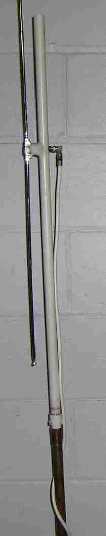
Completed antenna assembly. A right-angle adapter was added to the matching transformer's F-connector to remove any strain from the coax feedline.
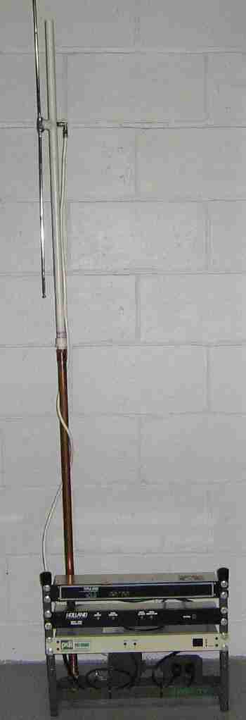
Completed setup.