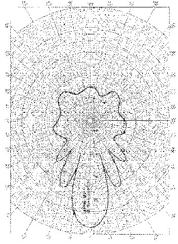
Figure 1 - Pattern of Directive Antenna
"Natural" Antennas
Mr. Robert Marcus, NCE
Dr. Bruce C. Gabrielson, NCE
Security Engineering Services, Inc.
PO Box 550
Chesapeake Beach, MD 20732
Introduction
A transmitting antenna is a mechanical device that converts the electrical power entering it into electromagnetic radiation. Conversely, a receiving antenna is a mechanical device which converts the electromagnetic wave impinging upon it into electrical power.
For antennas whose components are linear reciprocal elements, the reciprocity principle holds. That is, the gain of a receiving antenna is equal to the gain of the same antenna used as a transmitter. Wire antennas have losses associated with their impedance matching to air. Horn and reflector antennas with horn feeds have very low losses and these losses are normally neglected in antenna calculations.
Antenna Characteristics
Antenna characteristics are defined as follows:
Directive Antennas
A directive antenna concentrates the radiated power in one or more directions. If the antenna system is designed so that most of its power is concentrated into a comparatively small cone, the corresponding part of the radiation pattern is called the main lobe. There are always a number of secondary maxima, called side lobes, much smaller than the main lobe. The width of the main lobe is the angle between the half-power points. Half-power points are those points in the polar plot of the antenna pattern at which the power per unit area is equal to one-half that at the maximum. The field strength at these points is 1/ 2=0.7071 times the field strength at the maximum. This angle is also called the beam width. A typical antenna pattern of a directive antenna showing the main lobe and side lobes is shown in Figure 1.
Figure 1 - Pattern of Directive Antenna
It is possible for a "natural" directive antenna to unintentionally occur. Wiring that carries an intentional current directly or an unintentional rf current on its shield may be close to a rectangular shield placed vertically on a PC board. This shield can act as a reflector to form an antenna-reflector combination. The beam formed from this inadvertent combination will not be the sharp well defined beam associated with a "proper" antenna, but it will have directive properties to a certain extent.
Standing-Wave Antennas
Standing wave antennas, as the name implies, have standing waves of current and voltage on them. In a transmitting antenna of this type, a progressive or traveling wave is supplied from the power source. When the wave reaches an end it is reflected. The combination of the two waves sets up a standing wave pattern.
The current of the standing wave is always zero at an end and the voltage maximum, making the current and voltage ninety degrees out of phase. For very thin antennas the distribution of current and voltage is very nearly sinusoidal.
The simplest, and one of the most commonly used standing-wave antennas is the half-wave dipole. Figure 2 shows both a half-wave and a full-wave standing wave antenna.
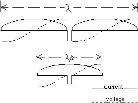
Figure 2 - Standing Wave Antennas
An unintentional standing-wave antenna can occur if rf is unintentionally coupled into a conductor by capacitive coupling due to its running parallel to a conductor carrying rf. If the wire is terminated in high impedance or has a ferrite bead around it to form an rf choke, reflections will start at the point where the rf choke has been placed. If the wire is longer than about one eight wavelength from the choke or high impedance point back to the coupling point, it will have a standing wave on it and will act as a standing-wave antenna.
Resonant Antennas
Many antennas are operated at or near resonance, which means that the reactive component of their input impedance is either zero or very small compared with the resistive component. An example of a resonant antenna is a center fed half-wave dipole. If an antenna is not resonant, it can be made resonant by adding either a capacitive or inductive reactance in series to tune the antenna to resonance.
Although antennas are not lumped circuit elements, the input impedance of the simpler type antennas, for a limited frequency band centered on the resonant frequency, is essentially that of a lumped series resonant circuit. The resistance at the resonant frequency is essentially the radiation resistance of the antenna.
As the frequency is increased, the wavelength becomes shorter and eventually a frequency is reached at which circuit conductors become an appreciable fraction of the wavelength. At this point they become radiating elements. It is quite possible for these conductors to form natural resonant antennas. A natural resonant antenna formed by circuit board traces is shown in Figures 3, 4, and 5.
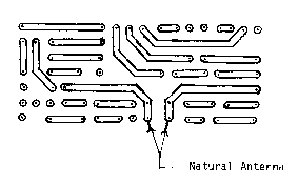
Figure 3 - Trace Formed Natural Antenna
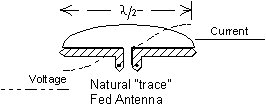
Figure 4 - PC Board Antenna Traces (only) From Bottom Showing
Standing Waves
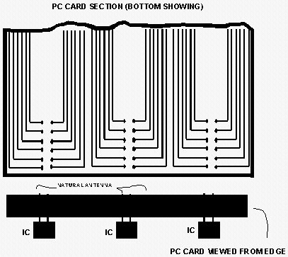
Figure 5 - PC Card From Top and Cross Section Showing Natural
Antenna
Traveling-Wave Antennas
A traveling wave antenna, as the name implies, has no standing waves. This is accomplished by terminating the antenna in its characteristic impedance so that no reflections occur. Examples of travelling wave antennas are Rhombic and Vee antennas. These antennas are directive and are usually several wavelengths long.
At microwave frequencies, a waveguide terminated by a horn is a form of traveling-wave antenna.
Any wire that is not shielded and is carrying rf current will radiate. If the wire or conductor is terminated in its characteristic impedance, it will have no standing waves and it will act as a traveling-wave antenna. Thus it is most important to use coaxial cables as much as possible in rf circuits. As was previously mentioned, rf can be unintentionally coupled into circuit board wiring which can form one of many types of antennas including traveling-wave antennas.
Influence of Near-by Conductive Bodies
The impedance of an antenna is affected by the presence of conductors in its vicinity and depends upon the degree of coupling between them and the length of the conductor. The coupling decreases with increasing distance. For bodies of comparable length the effect is negligible for distances greater than 2 to 3 wavelengths. For conductors less than a wavelength apart the mutual effect is the factor which forms the directive characteristics and modifies the input impedance of the antenna. Examples of these are an antenna and reflector or director combination and antenna arrays.
For an antenna set near a large conducting plane such as the earth or a large conducting sheet, the mutual effect is manifested in a different way. If the earth is assumed to be a plane surface and perfectly conducting it produces a mirror image of the antenna in the ground. A quarter wave vertical antenna above ground has the same voltage and current distribution as a center fed half-wave antenna(dipole). However its input impedance is one-half that of a half-wave dipole.
Unintentional antennas are also influenced by nearby conductive bodies thereby modifying their behavior. The unintentional antennas are one method whereby rf energy is radiated to the environment outside the equipment, especially if the equipment function is not to produce rf transmission. Careful attention to circuit layout can help avoid forming unintentional antennas.
Linear Antennas
A linear antenna is a straight thin rod fed by an rf source. It can be center-fed or end-fed. A center fed thin rod antenna is the familiar dipole antenna. Unintentional antennas can be linear antennas if they are straight thin conductors such as pc traces.
Half-Wave Antennas
The half-wave dipole, which is one form of resonant antenna as shown in the lower antenna of Figure 2, is most frequently used in the 100 to 3,000 MHz range, although it is also used less frequently at frequencies as low as the HF range. In the 100 to 3000 MHz range the free space length /2 is between 1.5 and 0.05 meter. However, the wave velocity in wire is less than that in free space and the actual length is somewhat shorter. The velocity factor is between 0.95 and 0.98 depending on the ratio of the antenna length to diameter ratio.
In the microwave region it is possible for unintentional antennas to be half-wave antennas as the circuit board length and hence the conductors can be a half-wave long. At 3 GHz a half wavelength is two inches long.
Wire and rod antennas are principally sensitive to the electric field of the electromagnetic waves impinging on them because they do not enclose any lines of magnetic flux. When the electric field is parallel to the wire or rod antennas the electric field produces a difference of potential along the length of the antenna. A loop on the other hand encloses magnetic flux in the area within the loop provided that the flux lines are at right angles to the plane of the loop. As the flux density varies with the wave motion current is induced in the loop.
Loop Antennas
A loop antenna is a closed-circuit antenna, that is, one in which a conductor is formed into one or more turns so that its two ends are close together. Loops are classified as either small or large. A small loop's total conductor length and maximum linear dimension are very small compared with a wavelength. A large loop is one in which the current is not the same either in amplitude or phase in every part of the loop. A large loop has different radiation characteristics compared with a small loop: its radiation is maximum perpendicular to the plane of the loop while the small loop's is maximum in the plane of the loop.
Unintentional loops can occur if a conductor has turns in it or if it loops around. One end may be grounded. Since the conductor has inductance and capacitance as well as resistance, a grounded conductor does not appear as a short circuit at rf and at some frequencies forms a loop antenna. If a conductor runs parallel to and is connected to the ground plane it forms a loop with the ground plane. To avoid these types of loops, grounded conductors should be kept as short as possible. If an unshielded conductor runs parallel to a shielded conductor it will form either a transmission line with the shield or form a loop with the shield depending on whether both of them are grounded at some point.
So called "ground loops" are formed when currents from different parts of the circuit flow through a common ground path. The path may be a ground plane, bus, or power supply. The current flowing through the loop generates a voltage which is applied to all the circuits using the common ground paths. The result is inadvertent coupling between the circuits. The coupling can be inconsequential or can produce significant positive or negative feedback.
Half-Wave Loops
The smallest size of a large loop is one having a conductor length of 1/2 wavelength. The conductor is usually formed into a square, as shown in Figure 6, making each side 1/8 wavelength long. The current flow is such that the field strength is maximum in the plane of the loop and in the direction looking from the low-current side to the high current side. If the side opposite the terminals is opened at the center as shown at B in Figure 6, the direction of current flow remains unchanged but the maximum current flow occurs at the terminals. This reverses the direction of maximum radiation.

Figure 6 - Half Wave Loops Consisting of a Single Turn Having
a Total Length of 1/2 Wavelength
Unlike a half-wave dipole or a small loop, there is no direction in which the radiation from a large loop is zero. There is appreciable radiation in the direction perpendicular to the plane of the loop, as well as to the "rear" the opposite direction to the arrows shown in Figure 6. The front to back ratio is in the order of 4 to 6 dB.
The ratio of the forward radiation to the backward radiation can be increased and the field strength likewise increased at the same time to give a gain of about 1 dB over a dipole, by using inductive reactance to "load" the sides joining the front and back of the loop. This is shown in Figure 7. The reactance, which should have a value of approximately 360 ohms, decreases the current in the sides in which they are inserted and increase it in the side having the terminals. This increases the directivity and thus increases the efficiency of the loop as a radiator.
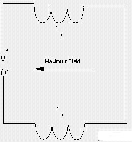
Figure 7 - Inductive Loading in the Sides of a Half Wave Loop
Natural Antennas Formed by Cables
Cables connected to circuit boards can form natural antennas. German, Ott, and Paul [1] have shown how the common mode current in a circuit board trace can be the driving source for an antenna formed by the cables connected to the circuit board. In Figure 8, the voltage drop across the lower circuit board trace, by virtue of its inductance and the current flowing through it, forms the driving source for the antenna formed by the cables. The resonant frequency of this antenna is much lower than that of antennas formed from the circuit board traces themselves.
Transmission Lines and Cables
In the previous section, it was shown that separate cables connected to a printed circuit board (PCB) can form an antenna. Transmission lines and cables can also radiate rf signals under other conditions. A parallel wire transmission line, as shown in Figure 8, has current flowing in opposite directions in each of the wires. The magnetic fields produced by the two wires will tend to cancel each other depending on the spacing between them. The closer the spacing, the greater the cancellation.

Figure 8 - Antenna Formed From Cables Connected to Circuit Board
Traces
The current flowing in opposite directions in transmission line wires or cable conductors is called differential mode current. If there is an imbalance in the line, the current in each side of the line will not be equal. The unequal portion of the current, called common mode current, is flowing in the same direction as shown in Figure 9. The field generated by a common mode current does not cancel and will radiate.
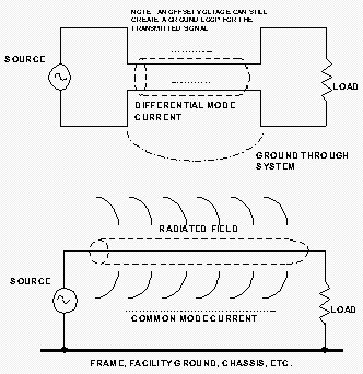
Figure 9 - System Ground Loop Antenna
Transmission lines should be kept as balanced as possible in order to reduce common mode currents. To reduce the field radiated by the conductors, the return path should be included in the cable adjacent to the transmission path and not routed through a separate ground return. The use of twisted pairs for transmission and return reduces radiation by keeping the oppositely flowing currents very close together.
Extended "Natural Antennas"
In addition to the occurrence of "natural antennas" on circuit boards and wiring harnesses, "natural antennas" can occur on the power wiring connecting electronic equipment to the power primary feeder lines. These antennas are very much longer than those on circuit boards or wiring harnesses. The rf conducted emissions on the power line can get back to the power primary feeder line through the utility pole transformer.
Figure 10 shows the power distribution extended antenna. The powerline ground has inductance which will keep the equipment side of the ground wire at an rf potential above ground. A number six wire has an inductance of 0.301†H per foot. A twenty foot ground wire has an inductive reactance of 37.8 ohms at 1000 KHz. At higher frequencies the reactance is proportionally higher. Therefore, the ground side of the power leads will be at rf potential above ground for any power line conducted rf emissions.
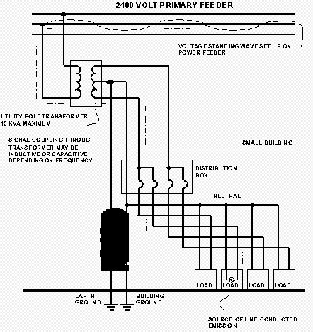
Figure 10 - Power Distribution Extended Antenna
The emissions will couple through the utility pole transformer to the primary feeder. The coupling will be inductive at low frequencies and capacitive at high frequencies. The latter is due to the capacitance between the windings. Thus there is an entire "antenna farm" of radiators for the conducted emissions. The emissions can be radiated great distances from the powerline, and also can be conducted for a fairly long distance unless they are suppressed at the source.
The Overall Picture
Natural antennas, which may be dipoles formed by ICs or loop antennas formed from circuit board traces, will radiate rf signals. Natural antennas formed by cables connected to circuit boards will also radiate rf energy. Conducted emissions on power leads can reach the power lines which appear as long wire antennas from which rf signals will radiate. Each of these sources of undesired rf radiation has to be considered if the generated signals or noise are to be prevented from radiating to the outside world. The best time to consider these factors is during the design stage to minimize retrofitting.
References
[1] "Effect of an Image Plane on Printed Circuit Board Radiation", R. F. German, Henry W. Ott, Clayton R. Paul, 1990 International Symposium on Electromagnetic Compatibility.
[2] "Radio Wave Propagation", Burrows, C. R., and Attwood, S. S., Consolidated Summary Technical Report of the Committee on Propagation of the National Defense Research Committee, Academic Press, New York, 1949.
[3] "Radio Handbook", Orr, W. I., Nineteenth Edition, Howard Sams & Co., Indianapolis, 1972.