Figure 1 - Energy Discharge Between Cloud and Ground [1]
Lightning Protection for Facilities
Dr. Bruce Gabrielson
Robert B. Marcus
Security Engineering Services, Inc.
PO Box 550
Chesapeake Beach, MD 20732
Introduction
The protection of facilities against lightning strokes is a rather involved subject well beyond the scope of this paper. Since a detailed treatment of the subject would take more time than available here, only the highlights will be addressed. However, several good references are provided if more information is desired.
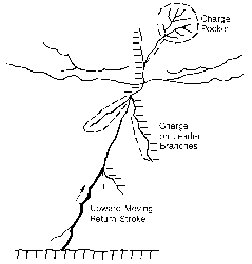
A lightning discharge, or flash, is initiated by an upward or downward traveling spark known as a step leader. When this step leader reaches the ground, a return stroke is initiated at the ground surface which moves back up the ionized channel left by the step leader, resulting in current conduction and the discharge of pockets of energy as shown in Figure 1. Since different clouds can contain varying amounts of charge, lightning strokes vary in intensity with a distribution of current as shown in Figure 2.
Figure 1 - Energy Discharge Between Cloud and Ground [1]
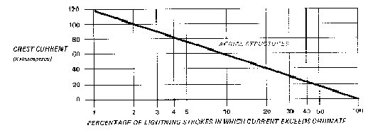
Figure 2 - Stroke Intensity Variation
Although less than two percent of all lightning strokes exceed 100 Kiloamperes, it has become the usual practice in industry to protect facilities against strokes at the 100 kiloamperes level. This protection normally consists of providing either a "zone of protection" for the structure, or of furnishing a conduction path on the structure to safely conduct the current to ground.
Zone of Protection
The zone of protection in the context of facility roof protection is the space located under the surface of a sphere having a radius of 150 feet when it is tangent to the earth, and is resting on a lightning protection air termination (addressed later). A zone of protection is also formed when the sphere is resting on two or more air terminals. Figure 3 from the National Fire Protection Code (NFPA 78) shows the zone of protection provided by a single grounded mast.

Figure 3 - Zone of Protection Defined by Dashed Lines [5]
Structures can be protected by an adjacent antenna terminal, and also higher roof structures on the same building. Such a case would be a two story roof section protecting an adjacent one story roof section.
The zone of protection for a one story/two story structure can be calculated for a 150 ft. striking distance from the following formula:
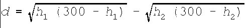
Where:
The zone of protection for single family dwellings is sometimes provided by an adjacent tree. However, any tree located 10 feet or closer to a house requires a down conductor independently grounded and tied into the facility ground to prevent side flashes.
Structural Protection
For lightning work, structures are divided into two categories: those under 75 feet high and those over 75 feet high. The structures lightning protection system consists of air terminals, down conductors, and facility grounding. In addition the building's electrical system has to be protected from overvoltage, plus all large metal bodies have to be connected to the main system to prevent side flashes.
Side flashes are simply an electrical spark jumping between two conductive but not connected objects during a lightning discharge. Often the sideflash occurs between a nearby metal body and the lightning protection system as shown in Figure 4.
Figure 4 - Example of a Side Flash [5]
The time waveform of the lightning stroke has a profound influence on the voltage conducted to ground on the systems conductors. Figure 5 shows the wave shape designation of a lightning stroke. The power industry has standardized a lightning impulse as having a 1.2 microsecond rise time (t1) and a decay time(t2), to the 50% current value. This wave shape is used for testing purposes and for designing the protection system. For a 100 kiloampere (kA) stroke with a rise time of 1.2 microseconds, the time rate of change of the current is 8.33 x 10¹⁰ amperes per second.
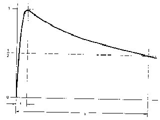
Figure 5 - - Wave Shape of a Lightning Impulse
A typical building lightning conductor has an inductance in the order of 15 microhenries per foot. The inductive voltage drop on a 20 foot run of conductor for the industry stroke is in the order of one million volts. In addition, if the ground rod has a resistance of 20 ohms to ground, there is a resistive drop of two million volts on the system. Therefore, the total voltage on the system during a stroke can be in the order of three million volts.
The breakdown potential gradient for air is approximately 13 kilovolts (kV) per inch, or 156 kV per foot. During a 100 kV stroke the three million volt potential on the system can cause a side flash to any conductor which is grounded but not connected to the system. This is the reason that all conducting bodies, metal equipment cabinets and the electrical system have to be connected to the building's main ground system.
Air Terminals
The uppermost part of the building's ground system is the air terminal shown in Figure 6. Minimum sizes for solid and tubular copper and aluminum air terminals have been set by the underwriters laboratory. As shown in Figure 7, air terminals are placed along the ridge of a sloping roof at spacings not to exceed 20 feet. On flat or gently sloping roofs, air terminals shall be spaced around the perimeter at intervals not exceeding 20 feet.
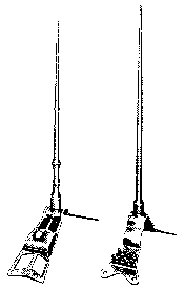
Figure 6 - Typical Air Terminal Design (Courtesy of Thompson)
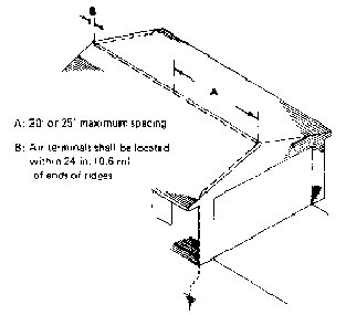
Figure 7 - Air Terminal Spacings [5]
Flat and gently sloping roofs are defined as roofs having a span of 40 feet or less and a pitch of 1/8 or less, and also those having a span of 40 feet or more and a pitch of 1/4 or less. Air terminals are necessary on elevations of non-conducting material such cupolas, ventilators, chimneys, spires or other prominent elevations.
Down Conductors
Air terminals are connected together and run to ground by means of standard conductors called "down conductors". For structures under 75 feet, standard copper conductors shall weigh not less than 187.5 lbs. per 1000 feet with individual wires not less than 17 gauge (NFPA 78 Code). A stranded copper conductor consisting of 29 strands of 17 gauge wire has a cross section of 59,500 circular mils (cm). If aluminum is used, the standard conductor shall weigh not less than 95 lbs. per 1000 feet with individual wires not less than 14 gauge. A stranded aluminum conductor consisting of 24 strands of 14 gauge wire has a cross section of 98,500 cm.
For structures over 75 feet high, standard copper conductors shall weigh not less than 375 lbs. per 1000 feet with individual wires not less than 15 gauge. A stranded copper conductor consisting of 28 strands of 14 gauge wire weighs 375 lbs. per 1000 feet, and has a cross section of 115,000 cm. A standard aluminum conductor shall have individual wires not less than 13 gauge with a total cross section of 197,000 cm. A stranded aluminum conductor consisting of 37 strands of 13 gauge wire has a cross section of 197,170 cm. A typical down conductor is shown in Figure 8.
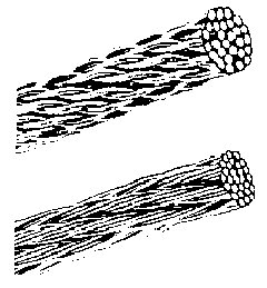
Figure 8 - Typical down Conductor (Courtesy of Thompson)
Facility Grounding
It is essential that the building ground system have a low impedance connection to ground. For buildings with a perimeter at ground level which does not exceed 250 feet there shall be not less than two down conductors. For buildings exceeding 250 feet in perimeter, there shall be an additional down conductor for each 100 feet of perimeter.
The building ground should have a resistance of from 20 to 50 ohms. In clay soil the ground should consist of a 1/2 inch diameter copper clad steel rod penetrating to a depth of 10 feet. The usual practice is to drive a 9 foot rod to one foot below the surface. The rod should be located two feet from the structure.
In sand or gravel it may be necessary to use additional rods tied together with a standard conductor and spaced six feet apart. If a ground rod cannot be driven due to bed rock near the surface, a conductor extending out from the building for at least 12 feet may be laid in a trench from one to three feet deep in clay soil.
In sandy soil or soil with considerable gravel, the conductor shall extend for 24 feet. If the topsoil is less than one foot deep, a standard conductor shall be laid in a shallow trench surrounding the building. If there are any crevasses in the bed rock, copper plates should be inserted therein and connected to the encircling conductor. All metal water pipes, well casings, and other large buried metal bodies such as oil tanks shall be connected to a down conductor. These connections cannot be used in lieu of a driven ground. If more than one water pipe system serves a building, they shall be connected together.
Large Metal Bodies
All large interior metal bodies such as heating and cooling ducts, metal piping, metal roofing, ventilators, and metal railings shall be connected to a main lightning conductor. Electrical equipment will be considered later. Exterior metal bodies such as storage tanks, eave troughs, and metal fences shall be connected to the main grounding system.
Electrical Systems
The electrical system shall be protected by means of secondary arresters. These are usually Metal Oxide Varistors (MOV's). A MOV is a device which changes in resistance as the applied voltage changes. MOV's act as a current shunt to protect loads as shown in Figure 9. Like zener diodes, the total energy of an applied transient must be shunted by the device, leading to various size devices depending on where they are located. They are rated for the voltage of the line they protect as well as for the current pulse that they can safely bypass. The largest MOV's will bypass 100 kA. MOV's in the electrical system are connected between the power line and the electrical system ground. The electrical system ground, in turn, is connected to the lightning protection system ground.
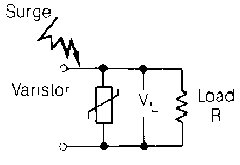
Figure 9 - Typical Shunt Varistor Application [1]
Electrical Equipment
All metal cabinets containing electrical equipment shall be connected to the building's main lightning conductors. In addition, while an MOV at the main electrical box will protect the electrical system, it is the preferred practice to also install MOV's at secondary distribution panels. These should be sized for the anticipated remaining pulse energy reaching the panel and the size of the load.
Most equipment varistors are quite small in size, and, although they can't bypass very large currents, they are very fast acting and clamp the transients to very low voltages. For example, motors require larger MOV's than a lighting circuit. Electronic circuits such as computers and communications equipment require that transients be clamped to fairly low voltages in the order of 50 volts or less. This is accomplished by using MOV's made especially for that purpose.
Antennas
Protection for antennas mounted on buildings will be briefly touched on here. It is a difficult subject and is covered at length in the references. Essentially, all metal antenna masts must be connected to a main ground conductor by means of a standard down conductor.
In the case of television (TV) antennas with 300 ohms twin lead, a 300 ohm twin lead lightning arrestor must be mounted on the mast and connected to the twin lead. For communications antennas and television antennas using coaxial leads, coaxial lightning arresters are available that will bypass 50 kiloampers. These may be mounted on the mast or on a metal panel which is in turn grounded to a main conductor.
Examples and Conclusions
Applying the above principles to protecting facilities nearly eliminates the probability of damage as a result of lightning currents. Figure 10 illustrates the basic protection for a steel building applied during construction. Air terminals are mounted on the roof and connected to the encircling roof cable. this cable is in turn connected to the structural steel frame. The steel frame is grounded as shown at every other steel column by means of driven ground rods.
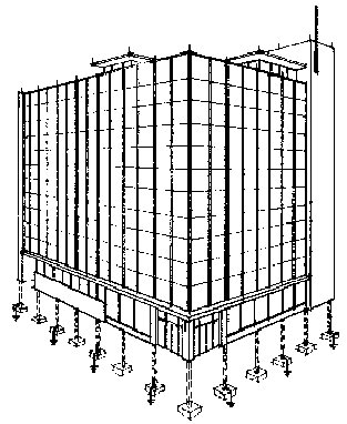
Figure 10 - Structural Building Ground With Every Other Steel
Footing Grounded (Courtesy of Thompson)
The illustration does not show the interconnections of all conducting systems such as water pipes, ventilating and heating ducts, metal electrical equipment cabinets, and the electrical system. Figure 11 shows the technique for attaching a bonding plate and conductor to the structural steel framework. Typically, three bolt holes are drilled and tapped for a solid connection.
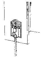
Figure 11 - Bonding Plate Attached to Steel Structure [5]
Figure 12 illustrates a typical family dwelling. Two types of roof slope are shown. The left and right side roofs are steeply sloped with air terminals on their ridges only. The center roof section has a more gentle slop so air terminals are required on both the ridge and the eaves.
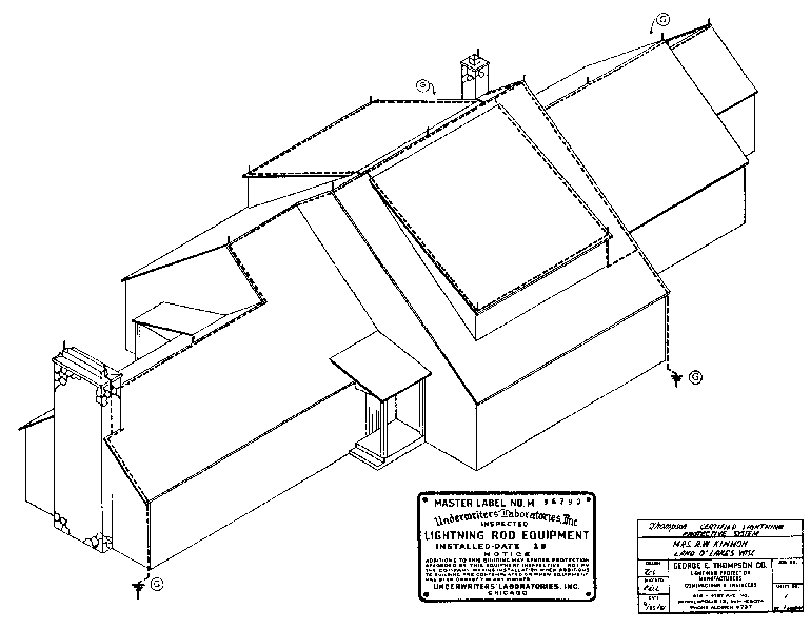
Figure 12 - House Protection (Courtesy of Thompson)
References
[1] Gabrielson, Bruce C., The Aerospace Engineer's Handbook of Lightning Protection, Interference Control Technologies, Inc., Gainesville, 1988.
[2] Thompson's Technical Manual, Thompson Lightning Protection, Inc., 901 Sibley Highway, Saint Paul, MN 55144
[3] Thompson's Lightning Protection, Inc., General Catalogue.
[4] Lightning Protection, R.H. Golde, Chemical Publishing Co., Inc., New York, N.Y.
[5] Lightning Protection Code, NFPA-78, National Fire Protection Association, 470 Atlantic Ave., Boston, MA 02210
[6] Master Labeled Lightning Protection Systems Underwriters Laboratories, 1285 Walt Whitman Road, Melville, L.I., N.Y. 11746
[7] Manual on Earth-Resistance Testing For the Practical Man, Biddle Instruments, 510 Township Line Road, Blue Bell, PA 19422
[8] Electrical Protection Guide For Land-Based Radio Facilities, by David Bodle, Joslyn Electronic Systems, Santa Barbara Research Park, P.O. Box 817, Goleta, CA 93017
[9] Lightning/EMP and Grounding Solutions, PolyPhaser Corporation, 2225 Park Place, P.O. Box 9000 Minden, NV 89423-9000
[10] How to Select GE-MOV Varistors for Transient Voltage Protection, General Electric Semiconductor Products Department, West Genesee St., Auburn, NY 13021