INTRODUCTION
This test is being sponsored by the Live Fire Test and Evaluation (LFT&E) Office which is part of the Office of Test and Evaluation (OT&E) under the Office of the Secretary of Defense. The test consist ed of a test suite performed in FY96 encompassing EM susceptibility tests. The HPM Test Facility, Junction Ranch, NAWC, operated by the Radar Cross Section Outdoor Branch, Electronic Combat Range, at the Naval Air Warfare Center Weapons Division, China Lake, California, was selected as the location to conduct this test in cooperation with the Helicopter Dynamic and Static Rotor Blade Ballistic Vulnerability Test, Task I, FY96. The AH-1S Cobra Helicopter was selected as the test object for coupling analyses because it was available in quantity, was suited for external and internal coupling measurements, provided access to subsystems, and was available for this type of testing. The purpose of these tests is to confirm computational model pre dictions for the system susceptibility and to then ex trapolate that knowledge to computational models of other systems about to enter production; specifically the RAH-66 Comanche helicopter.
The general electromagnetic environment of the aircraft includes both externally-generated high intensity radiated fields and internally-generated radiated or conducted emissions. Part of the tasks of this test suite was to evaluate not only the external threats, but to also gauge the severity of internally generated threats for comparison with the model's predictions. The ability to withstand internally-generated emissions is often referred to as electromagnetic compatibility.
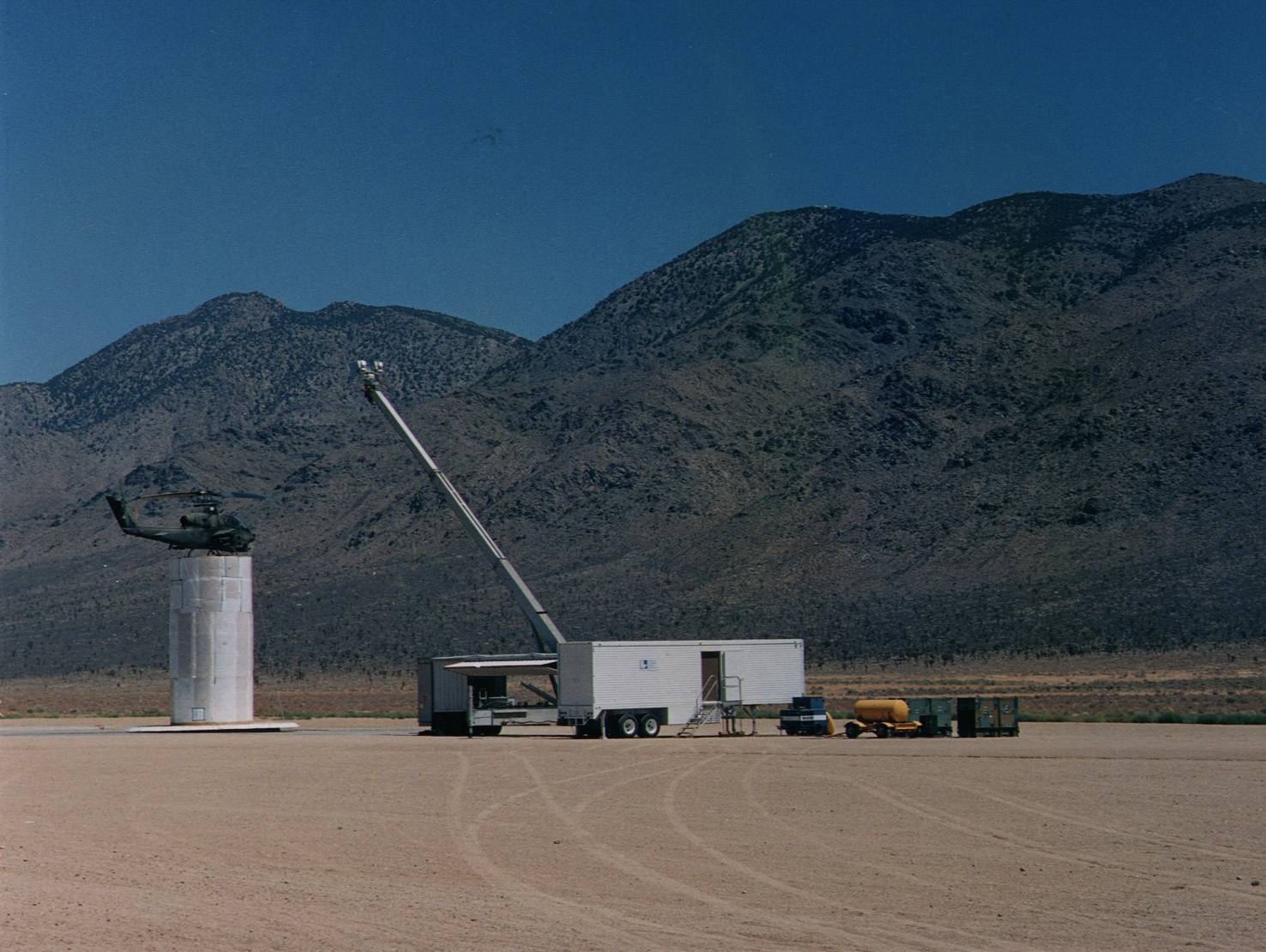
Figure 1. the test site during low power testing
BACKGROUND
The test series had three principal motivations:
- to provide specific susceptibility information on the
AH-1S,
- to evaluate and compare the computational electromagnetic model to the test data, and
- to extrapolate these test results and computational data to the RAH-66 for use in that phase of the second part of this effort.
The purpose of LLNL's low power experimental tests was to validate its computational models for its OSD activities in support of the Live Fire test pro gram.
``The data from the live fire tests are not in tended primarily as a means of improving the computer modeling capability of the design com munity although that is certainly a spin-off. Rather, the primary purpose of these tests is to gather first- order insights into the total ability of a given system to withstand and/or inflict combat damage, includ ing all of the synergisms. Live fire tests are neces sary, and so are computer models. One cannot substitute for the other.'' -- James F. O'Bryon, As sistant Deputy Under Secretary of Defense, Aug. 1996.
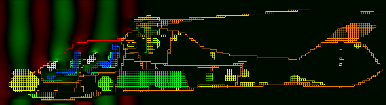
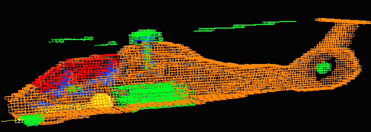
Several previous classified and unclassified1 experiments illustrated the need for combined experiments and analyses. Specifically these results, when extrapolated to the RAH-66, will aid in the development of that system. Based on previous experiments2, the wide frequency bands used in this experiment have been found to be susceptibility points for a broad class of electronics systems and represents a peak of the coupling band obtained by combining the coupling into air frames and the sus ceptibility of components/subsystems. Thus, the main coupling points and bands which were isolated as part of this experiment, were those which (a) provide sufficient coupling to the air frame body, (b) are able to penetrate into the interior of the air frame, (c) are able to couple to the electronics of the aircraft, and (d) are susceptibly points. The consequences of (d), will be applied to the electronics proposed in RAH-66 as part of the later analyses. It is generally easier to separate the stress (fluence coupled to assemblies) and strength (failure limit of assemblies) portions of the EM testing since strength testing can be done on the subsystem or component level in a bench top environment and does not require the full aircraft after the localized stresses have been established.
Testing on the RAH-66 has previously been limited to environmental concerns (lightning and static charge), lower frequency measurements3 on the air frame, and higher frequency measurements on the flight control system (Dahlgren, VA). The prime focus of LLNL's experiments was centered on the higher frequency bands, those that have subsystem and component level susceptibilities which have been demonstrated previously4, and those where air frame coupling is expected to be high. An initial question that was examined as part of low power material testing5 indicated that the composite skin of the RAH-66 would not couple high frequencies much differently than non-composite materials. On the other hand, one issue that was not directly addressed by the experimental test series was the required minimum windscreen metallization needed to provide effective shielding for the interior. This process will be better evaluated as part of the computational analysis of the RAH-66.
Note that seam and crack penetration effects due to vibration (in-flight dynamics) of the air frame were not performed due to time and logistical constraints. This issue is important to resolve since it greatly impacts the computational comparison effort. It was felt at the time that the process of accessing the internals of the airframe was similar to the kinds of day-to-day variances that vibrational effects could have provided. This issue will be addressed in more detail during the operational testing scheduled for Summer of 1997.
APPROACH
The experiments were conducted on an electrically complete AH-1S aircraft (except for the battery). It is critical for this series of electromagnetic tests that the air frame be in its ``pre-modified'' configuration; e.g. the standard operating condition before modification for the Rotor Blade Ballistic Vulnerability Test series. This was especially important for the avionics sections and the additional shielding that the BVT added to the air frame. This did not pose a problem since the aircraft used in the electro magnetic testing were succinct from those used in the ballistic testing.
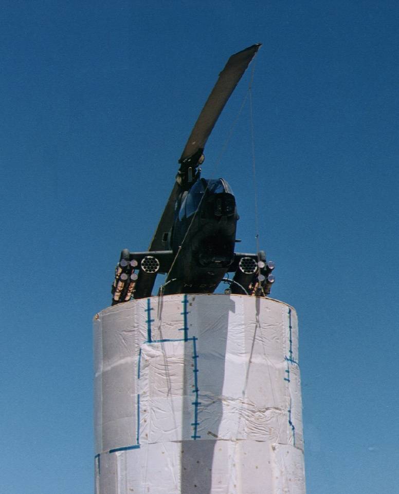
Figure 2. AH-1S with weapons pods
The helicopter was tested in three configurations which allowed for from below illumination (45o declination), from above illumination (45o elevation), and nose-on illumination (0o elevation). In particular, the from above orientation was expected to be most susceptible to windscreen coupling and access lines via rotor ports while from below coupling was expected to be induced through instru mentation and weapons bays. The coupling and susceptibility analysis consists of several instrumentation geometries as described below. These geometries are designed to
- provide preferential
coupling into the main body of the air frame,
- provide optimal resonant coupling onto feed lines,
and
- deposit energy on-target to susceptible sub systems. The combination of these three is easily recognized as some of the goals of a typical RF as sessment analysis for weapons and communications systems.
In the course of testing the aircraft, it was necessary to expose the helicopter from a vari ety of orientations. These orientations can be achieved by rotating the helicopter around the cen ter point. The goals of changing the orientation are three fold:
- to align major feed lines with the polarization of the incident wave field;
- to orient the
major cavity coupling paths to the direction of the
incident wave field; and
- to reduce standing waves formed between the air frame with the surrounding platform, the ground, and the RF source trailer.

Figure 3. inside of tower looking at optical fibers
The 9000 lb. weight of the helicopter posed struc tural requirements on the support tower which were addressed through the use of high denisty urethane foam. This tower formed the base of the support structure and was topped by a spherical vaulted cav ity and a wooden platform to distribute the weight of the helicopter. The tower had the following prop erties suited for electromagnetic testing:
- low scattering cross section (foam construction)
- very low metal parts count
- minimal wavefront blockage between the
source and the object under test
- the ability to rotate the object-under-test on the
platform
- the ability to withstand the vibrational modes of operation of the test object
MEASUREMENT INSTRUMENTATION
The major cavities and compartments of the air frame were instrumented using a variety of RF probes, including non-obtrusive monopoles and field probes, to measure volumetric resonances in the internal cavities. Strategic feed lines were in strumented using high frequency current probes.
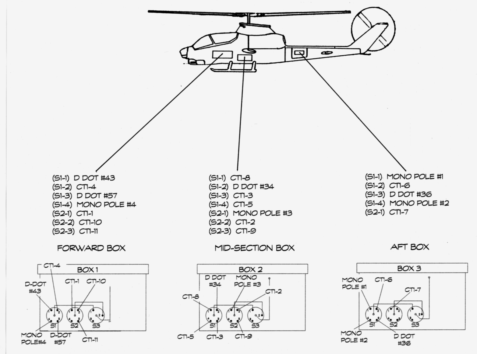
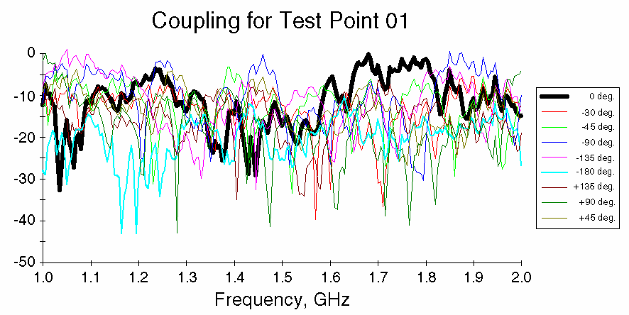
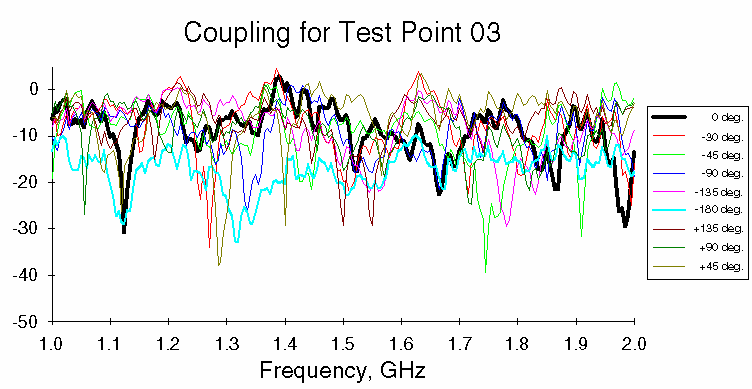
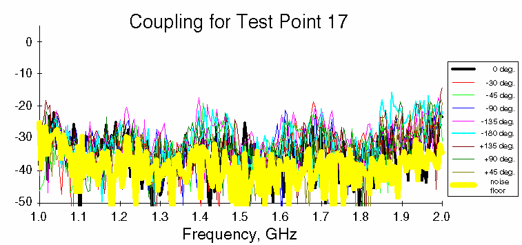
Figure 4. test points in the low power test
Signals from the various instrumentation packages were conveyed from the aircraft to the recording computers through a series of fiber optic transceivers to avoid the severe losses and intrusiveness into the test volume that would have occurred by using coaxial cables.
Incident RF Power
The incident RF power was provided from the RF source (see fig 5) in the LLNL portable source trailer. The transmitted energy was launched from the broadband antenna attached to the top of the extendable mast shown previously in figure 1.
Figure 5. 200W TWT sources generate output RF
The RF sources in the portable source trailer were swept from 100 MHz to 4 GHz in order to get the broad spectral characteristics of the helicopter in the instrumentation configurations mentioned above. The source was connected to the transmit antenna on the top of the extensible mast through the con necting coaxial cable. The output power density from the source was a maximum of 1 W/m2 at an operational distance of 10 meters.
Transmit antenna
The output power was radiated through broad band transmit antennas that had a spectral response covering the operating frequencies. The gain, and hence the beamwidth, of the antenna varied as a function of frequency but was broad enough to cover the test region at a distance of 10 meters. The antenna is positioned at a slight angle to prevent resonances between the air frame and the antenna itself. The mutual coupling between the antennas was taken into account during the measurement us ing both the low-frequency antenna pair and the high-frequency antenna pair. The initial operating polarization was vertical but was alternated between vertical and horizontal during the tests. The interaction of the antenna polarization with the ground and the tower determined which polarization not to use. The interaction of the polarization with the helicopter assemblies determined which polarization to use.
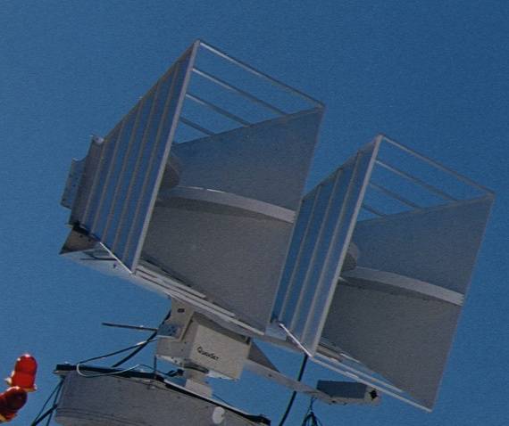
Figure 6. low-freq. broadband antennas
Incidence angles
There was a need for three incident angles as part of this test suite which included:
- a look down angle from above with the heli
copter on the tower to aid in windscreen coupling
mechanisms for the dominant coupling angle.
- a look up angle from below with the helicopter
on tower to utilize weapons pod and structural
member coupling and included that from feed
lines and interconnects. This mechanism was expected to be of secondary nature due to the existing shielding of the air frame external structural
members but, unlike the windscreen effects, is
prone to buildup of standing waves corresponding to the physical lengths of the connecting lines.
- a nose-on illumination with the helicopter on the tower to examine main body and front compartment coupling mechanisms.
Test Aircraft
This test used the AH-1S helicopter in an instru mented configuration. The aircraft was in a fly-able condition and was intact, operational, and contained cabling and wiring assemblies in their original positions. In general, test specimens were selected from the body of samples such that:
- replacing cabling and wiring assemblies was
minimized;
- subassembly replacement simulations (dummy
loads) were not necessary;
- covering unnatural apertures (holes) was not
needed;
- seams and joints were in their ``original'' con
dition and did not require refitting;
- body panel matching was not necessary; and
- weapons systems and pods were consistently
added and modeled.
To be explicit, it was specifically desired that the aircraft used as part of this electromagnetic testing contain its avionics packages and not have additional armor (added to many of the samples for the Helicopter Dynamic and Static Rotor Blade Ballistic Vulnerability Test, Task I). Coordination between the two tests occurred such that the goals of both tests could be achieved without disruption to either.