 .:: HERF001 ::. .:: HERF001 ::.
|
Purpose:
The purpose of this lab is to find a way to power a microwave oven magnetron from a portable power supply.
Materials:
- 10kV DC-DC inverter module
- 5kV ~6.67uF oil filled capacitor
- 1kW 2.45 GHz Magnetron
- Horn Antenna w/ built in waveguide
- 6V coil / 600VAC 35A mercury contactor
- 15V voltmeter
- 500mA ammeter
- 3A ammeter
- 250uA ammeter (converted into a 5kV voltmeter with a series 20MOhm resistor)
- 4" PVC pipe
- Indicator bulbs
- On/Off lock switch
- Momentary push buttons
- Heavy duty wire
Procedure:
I will test how much power an MOT feeds the magnetron to both the cathode and the heater. I will then try to replicate the same power by using an automotive battery as a power source that will charge a capacitor. This capacitor will pulse a magnetron for a breif moment transmitting ~1kW of RF power for a breif moment. The heater will be activated before the cathode is pulsed until it reaches nominal temperature.
Results:
7/16/01 - Horn antenna calculations have been made for a 21dB gain for a 2.45GHz megnetron source. I will now need to purchase copper sheet metal and welding supplies. Once tests are done using a continuous 2kW power source then the power supply will be switched to the 12V pulsing supply.
7/25/01 - The pulsed power supply was a great success! I powered the heater using the origional supply. Then, I charged the pulse power supply to 5kV and pulsed it. The needle quickly fell to 3kV - 4kV and stopped. It was then simple to quickly bring up the charge to 5kV again. My conclusion from this was that I need a much more powerful charger and a higher voltage rating storage cap. The reason for a higher volatge than 5kV is because at 5kV the HERF was putting out the most RF power, meaning that I have not yet reached the peak (probably around 6kV - 8kV). My next setup will use 8kV 16uF instead of 5kV 7uF.
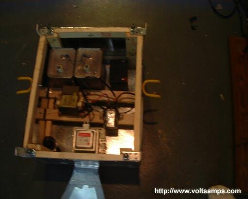
8/14/01 - I have gotten very far with the HERF's outer body and its inner workings. It is setup as a hybrid and can run on either wall power or batteries. I already have the fan set up and the digital panel meter for reading the capacitor charge. There will be over 8 switches and 2 lights on the control panel.
9/02/01 - The HERF is practically complete. The following images show my progress in development. The HERF will soon be able to run from a 12V automotive battery when I get my 2kW inverter. For now it runs directly from my home power supply.
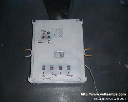
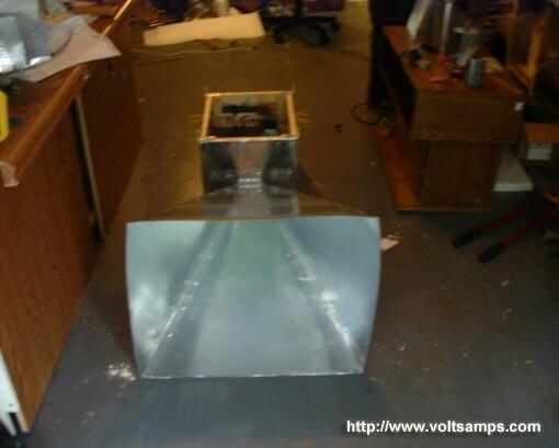
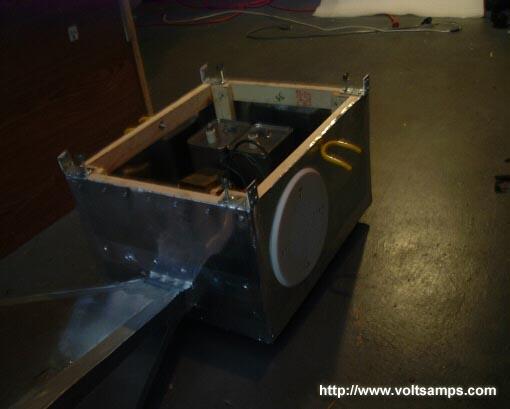
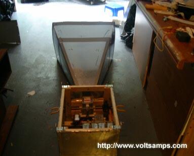
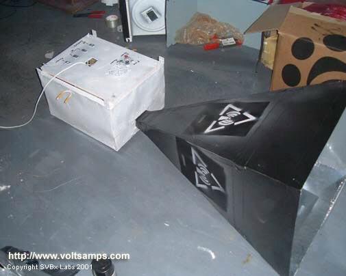
HERF001, top view.
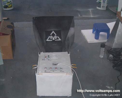
HERF001, back view.
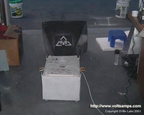
HERF001, back view.
HERF001, top view.
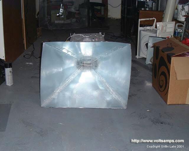
HERF001, side view.
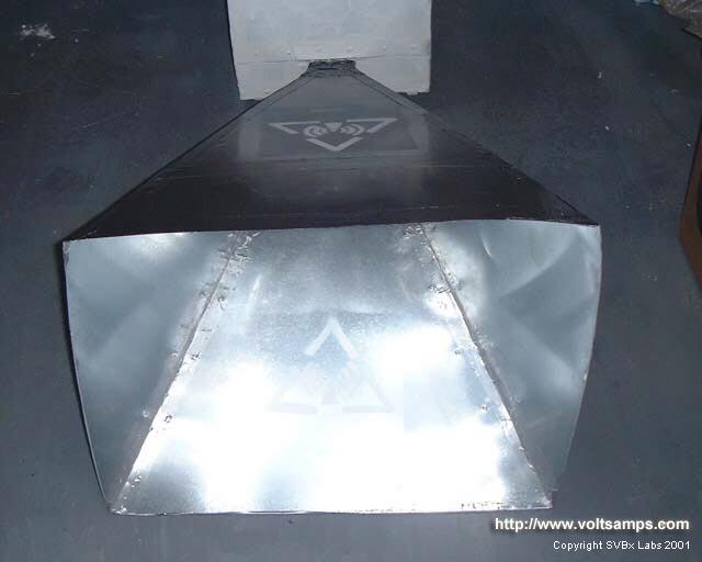
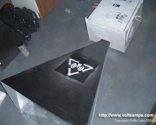
Horn antenna front view.
Horn antenna front view.
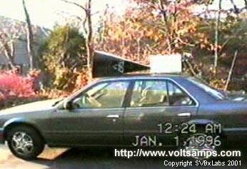
Wanted to see what the HERF001 would look like on top of my car. It's a bit bulky and would experience a lot of viscous friction. An actual car mounted HERF would have to use a higher frequency so that the same antenna gain can be accomplished using a much smaller antenna. If the antenna is small enough it can even be placed in a over-head lougage car attachment. It would even be possible to have the horn antenna in the trunk and have it radiate through a fiber glass window. For check-point security, an x-ray or radio camera can be used to spot this.
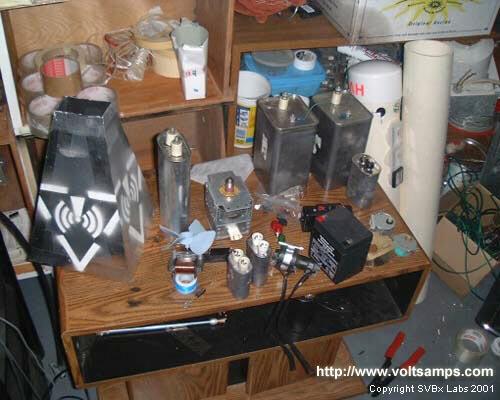
These are some of the parts used for testing the magnetron before constructing the HERF.
|
© Copyright Rostislav Persion 2003
|


 IP LOGGED: