 .:: PFN ::. .:: PFN ::.
|
Purpose:
The reason for this project is to simplify the type-e pulse forming network so that it can easily be constructed out of inexpensive materials.
Materials:
- Sheet Metal
- High Voltage Dielectric
Details:
Pulse forming networks (PFN) have been used frequently for many applications, including radar. The purpose of a PFN is to shape a pulse as it is discharged through a resistance. In radar applications a type-e PFN is desired because it is designed to pulse a square wave through a magnetron.
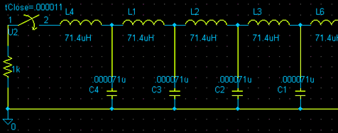
This is part of a schematic of a PFN. You do not need to worry about the rest of the schematic because it repeats. The type-e PFN consists of capacitor/inductor modules which all have equal capacitance values and inductance values. These modules are called meshes. It does not matter how many meshes your type-e PFN has, as long as the total capacitance and total inductance are as calculated. In fact the more meshes you have the more "square" your output waveform will be. When you charge the PFN and pulse it into your load, you will notice that only half of the voltage is applied across this resistance. This is another property of the type-e PFN (if your magnetron requires a 16kV pulse then you must charge your PFN to 32kV).
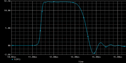
This is the output of a type-e PFN with 14 meshes that is designed for a 2uS pulse on a 1kOhm load. The total capacitance of the PFN is 994pF which means that each mesh should have a 71pF (994pF / 14) capacitor. The total inductance of the PFN is 994uH which means that each mesh will have a 71uH (994uH /14) inductor. The formulas for figuring out the total inductance and capacitance are the following:
C = T / (2 * Z)
Where:
C = Total Capacitance (F)
T = Time (S)
Z = Resistance (Ohm)
L = (T * Z) / 2
Where:
L = Total Inductance (H)
T = Time (S)
Z = Resistance (Ohm)
If we examine the type-e PFN closely we see that the more meshes we have, the more square and perfect our wave is, and the smaller capacitance and inductance values we need. This made me think in terms of calculus and made me realize that the same PFN can be built as a single capacitor with a high inductance. The task for calculating the capacitor dimensions seemed daunting at first but then I realized how simple it was.
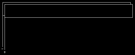
All that needs to be done is to construct a capacitor that has the desired total capacitance so that when the two plates are placed in series, the inductance equals the total inductance. After this idea had entered my mind, I decided to test it out in a circuit simulator.
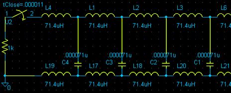
First I modified the original PFN so that it has inductors on both sides (just like a double plate capacitor). I had not yet changed the values on it.
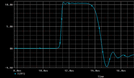
Then I tested the circuit. It seemed to function the same way except that the pulse duration was a bit longer and my peak current was a bit lower than expected.
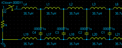
I then went and divided all the inductor values by two, so that the total inductance was as previously calculated.
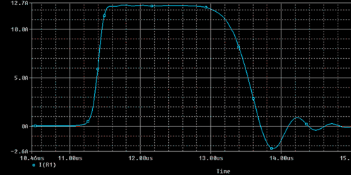
This worked like a charm. The output was exactly the same as the original PFN proving that a perfect PFN could be built just from two sheets of metal with a dielectric in the middle. This automatically solves the problem of insulating and winding inductors for a type-e PFN. It also allows you to construct the entire PFN without the need of special value HV capacitors. I will leave the rest of the calculations for you to figure out.
|
 |
|


