.:: [01-18-04] ::. .:: [01-18-04] ::.
|
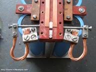
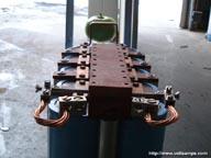
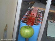
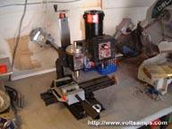
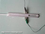
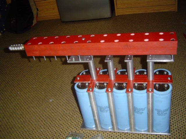
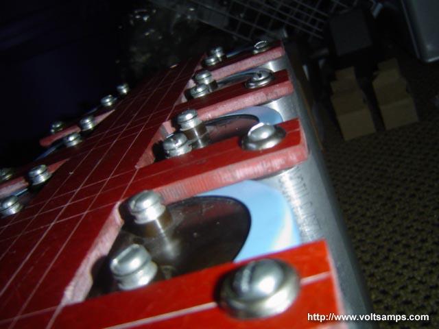
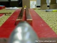
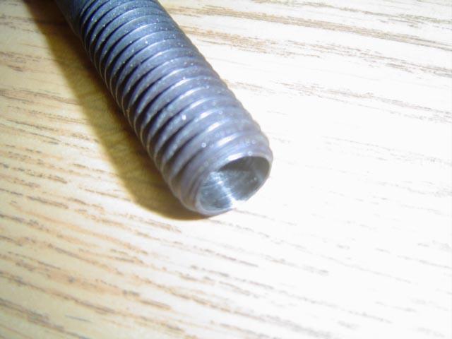
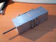
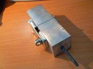
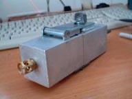
My apologies for the long delay however I decided to post when I am actually done with the railgun. Since my last update a lot of work and thinking was done. I completed the power supply and the entire railgun setup. I decided to use a ballistic pendulum for speed measurements because it was the most reliable and least intrusive method I could think of. Because I will fire the rail gun soon, I will keep this post brief and explain all the small details after the first shot has been fired. I will have two camera angles of the shot for better viewing and will post the videos on the site. For now, enjoy the latest images of the completed railgun.
|
|
|
.:: [11-30-03] ::.
|
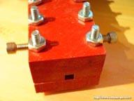
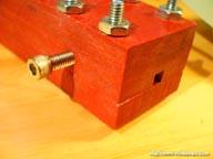
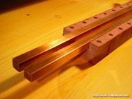
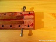
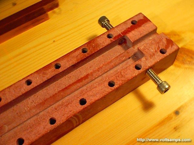
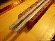
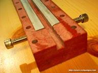
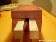
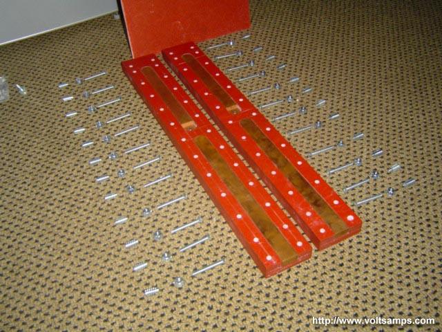
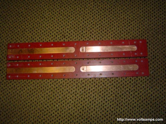
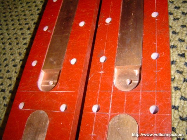
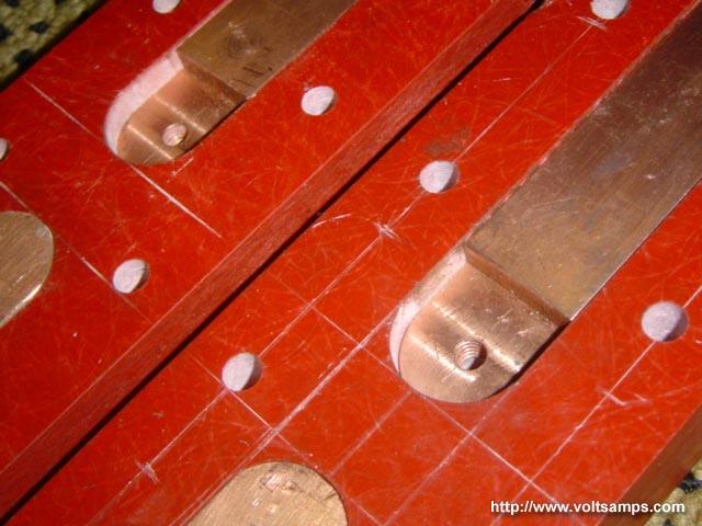
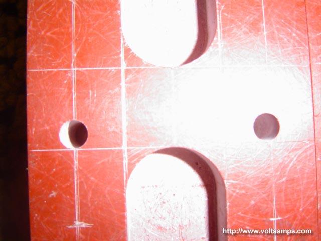
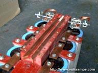
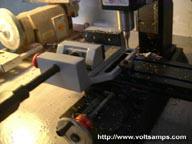
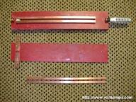
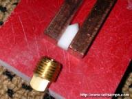
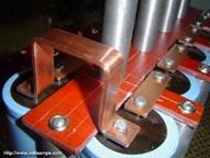
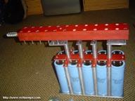
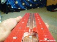
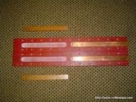
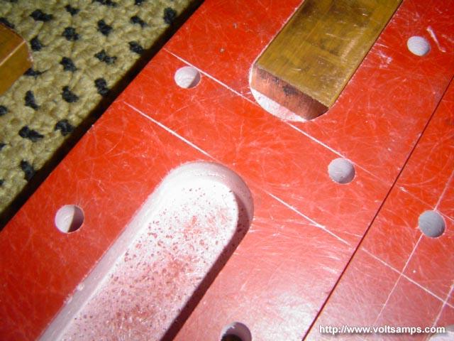
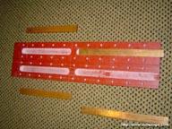
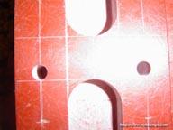
I finally returned home for Thanksgiving break and had a chance to put my new milling machine to use. I got a whole lot of work done in this time and as you can see I am one of those people who makes many design changes. Being an engineer and machinist at the same time is always a challenge. My main focus for now was completing the rail stack. I made a trench for the projectile to slide through with a slight clearance which made a good seal, and also made a trench for the rails to fall into. The images however do a better job at describing this. During machining I decided that it would be easier to replace the rails if I remove the front portion of the rail stack. This exposes the front of the rails and also acts as a muzzle flash suppressor by deflecting the sparks upwards and downwards until the projectile has left the tip of the rails. The rails can be removed by loosening the clamping screws that hold the rails in place and also act as the source of current. The images show the rail stack from different angles with copper rails, aluminum rails and no rails.
|
 |
|
|
.:: [10-08-03] ::.
|
Today was somewhat of a slow and disappointing day in the shop. I intended to finish the entire rail stack by machining the rails, enclosure, and rail terminals. Unfortunately it seems a machinist there by the name of Bob had complained to the building director about the epoxy resin smell from the fiber glass. I am no longer allowed to machine fiber glass in the shop so I worked on the metal stuff. I was able to finish the terminals and two sets of throw-away rails. I asked if I could quickly cut the fiber glass into the proper rectangular shape on the band saw and luckily got an okay. This will probably delay the completion date of the project but fortunately I ordered my very own vertical milling machine last night which I will be able to use to complete the rest of the work. Hopefully everything turns out well and once again I would once again like to thank Bob the SUNY Stony Brook University machinist for delaying my project and costing me hundreds of dollars. Thanks Bob :-).
|
|
|
.:: [09-24-03] ::.
|

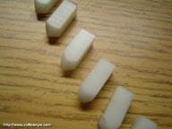
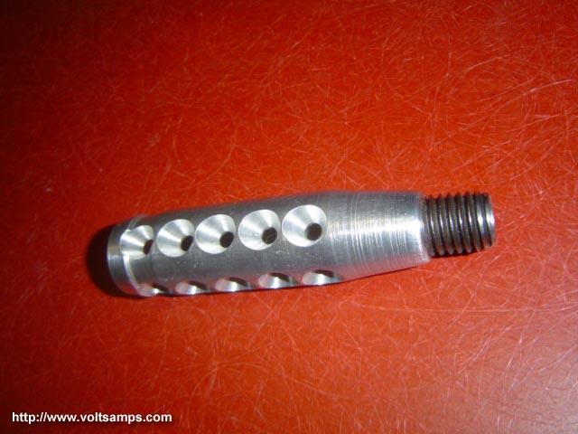
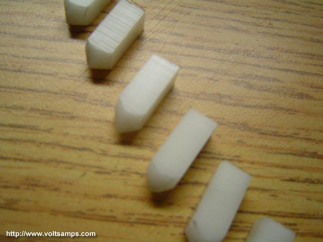
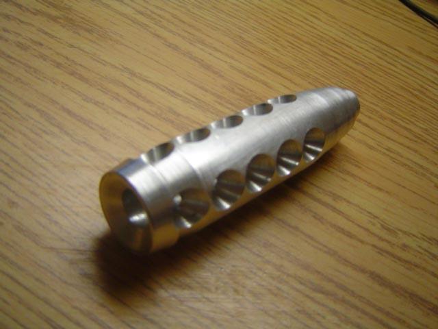
Lots of work was done today. I was able to complete three parts of the railgun. The copper bus bars, the muzzle flash suppressor and the projectile tips were all completed today. As some of you that already spoke to me may already know, I made some big design changes that will improve the performance of the gun and will allow me to get large efficiencies from the capacitors. I decided not to use any kind of injection at all however I will try to accelerate the projectile not only electromagnetically but electro thermally. Why waste all that energy thats lost in vaporizing part of the projectile? I plan to use plastic projectiles which I machined today with a plasma armature pushing it from behind. The material that triggers the initial plasma will vaporize and will create a large pressure behind the projectile which will help accelerate it. This method will utilize only electrical power for acceleration which will make this railgun a true railgun. I appologize for the design changes I have made but I think they were for the better and like I said I am open to suggestions from viewers and this is proof. Believe me the design change was expensive but it will be well worth it :-).
|
|
|
|
.:: [09-22-03] ::.
|
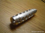
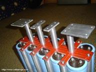
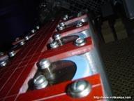
Today I focused mainly on machining the remaining standoffs that go around the capacitor bank and the standoffs that hold the rails above the capacitors. I also machined some platforms that mount to the standoffs which have threaded holes that the rails mount to. I also spent a considerable amount of time working on a fancy looking muzzle flash suppressor. I have yet to thread it so that I can screw it into a bolt that I hollowed out. I tried assembling the rails gun with all the pieces I machined so far and the old rails just to get a feel for what it will look like at the end. The picture does a good job at foreshadowing its appearance however the rails will be shorter, and they will be flush with the standoff platforms. There will also be other components on the rail gun.
|
|
|
.:: [09-17-03] ::.
|
Lots of work was done today, however I made a huge design change which will set me back somewhat both in funding and time. I was unable to find a non-lead core .22 caliber bullet and also worried about internal arcing due to the small distance between the rails. Many people suggested machining my own projectiles and I chose to take their advice. I am changing my projectile to a 0.3" x 0.3" extruded square. This will allow me to clean the rails after each shot and will allow me to experiment with various projectile designs. I will still use combustion as a means of acceleration. I will use either a combustion nailgun shell or a blank. I tried my best to convert my current rail enclosure to the new projectile specs however there is a much better way to make this kind of setup. I ordered new materials and will begin machining the new rails as soon as the parts arrive. For now I will work on the capacitor bank and mounting hardware.
|
|
|
.:: [09-15-03] ::.
|
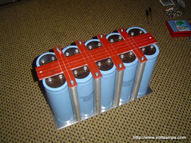


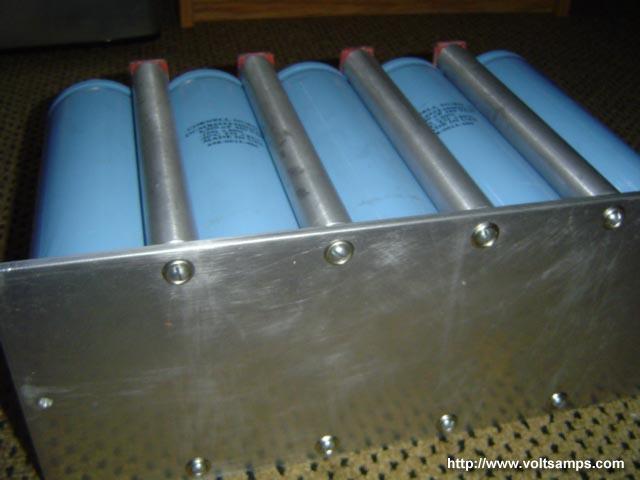
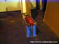
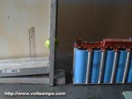
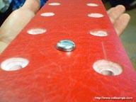
Today was a very productive day. My objective was to make a capacitor box from a 1/4" sheet of fiber glass, a 1/4" sheet of aluminum and a 6' long 1" diam aluminum rod. I decided to go with this design instead of a box because it is a whole lot stronger. I machined 6 stand-off posts on the lathe making them the propper length, then drilling and tapping. I need 8 posts total however did not have enough length of aluminum for this so I ordered another 6' length today. The fiber glass was cut so that it clamped the capacitors down yet exposed the terminals so that I could run bus rails over the GP03 material. There is also a space in the middle where the rail enclosure will sit. The rails are next in line for machine work.
|
|
|
.:: [09-10-03] ::.
|
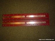


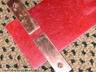
My next step was to round the copper bars so that I can fit them into the fiber glass as snug as possible. I used a radial bit on a vertical mill to round one side at a time. However, I firt flattened the ends of the rails so that I can fit a dielectric in that space. The reason for this is the terminals must be behind the projectile entry point otherwise the current will flow backwards and will decelerate the projectile. I drilled some holes for the terminal bolts and threaded the holes with 1/4"-20 tap. Most of my railgun will use 1/4"-20 threading so that I can reuse screws and nuts. The rest of my materials should be in transit now and will arrive soon.
|
|
|
.:: [09-08-03] ::.
|
Today I machined the GP03 electrical grade fiber glass material that will be used to hold the injector stage and the rails within. I used the vertical mill to carve out trenches for the rails to fit into. I faced the option of making the trench rectangular or rounding the copper alloy 110 rails and decided that rounding the copper would be better. The less I machine the fiber glass the smaller the chance of it breaking from the rail repulsion and from the 3kPSI to 20kPSI injection. After the copper rails are fitted inside the fiber glass and the dielectric spacers are inserted the two sides are then bolted together. Using the vertical mill I was able to achieve extremely high precision. There is a 2cm space between the injection stage copper bars and the rails for isolation purposes. The rail trenches are 1mm deeper than the injector trenches in order to provide room for the dielectric spacers.
|
|
|
.:: [08-12-03] ::.
|
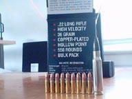
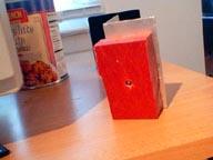
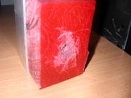
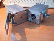
Before I could settle on a chemical propelant injector (gun ammo) I first had to see experimentally if my injector could withstand the pressure that would be generated by the gun powder. Methematically I was able to calculate the wall thickness needed to safely withstand the pressure however a real-world test is what would convince me best. I constructed two simple experimental injectors. One was made from GP03 electrical grade fiber glass (tensile strength of 10kPSI) and the other from aluminum alloy (tensile strength of 45kPSI). Both held up to the blast however the fiber glass version was slightly harmed with each shot. Thus I decided that my injector must be lined with a metal surface. Initially I searched for the smallest caliber bullet I could find which was a .22 caliber diameter. I was very tempted to use the AK-47 bullet (.308 caliber) however I was too worried about the extremely high pressure that would be generated, on the order of 60kPSI. With the AK round I would be able to get injection speeds of upto and over 3000fps. The bullet is also available with steel core and would conduct a whole lot better than lead.
|
|
|
© Copyright Rostislav Persion 2004
| |


 IP LOGGED: