 .:: Shape Memory Alloy Robot ::. .:: Shape Memory Alloy Robot ::.
|
Purpose:
The purpose of this project is to find out how practical shape memory alloy is for robotics. Shape memory alloy also known as muscle wire, Nitinol, nickel titanium alloy or just SMA, is a mix of two different metals which gives it a "shape memory" property. You can deform this material and it will return to its original dimensions after heating it. This material was originally used in frames for glasses and is now experimental in robotics. The benefits of using SMA linear actuation are that it produces a silent motion and requires a simple driving circuit with no feed-back sensors. I will construct a robot and evaluate it's performance to see if shape memory alloy is practical for use in robotics.
Materials:
- Erector set
- 50MHz microcontroller
- High power MOSFETS
- SMA actuators
- Battery pack
- Wires
Images:
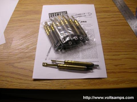
This is the back of shape memory alloy (SMA) actuator that I ordered sitting on top of the spec sheet. Each one requires at least 1 to 2 amps of current in order to contract. Contraction times are less than a second with no load. Then 12 seconds of rest is required before pulling the actuator apart to its original state.
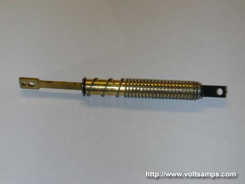
This is a close-up photo of an SMA linear actuator. Notice the protection spring which protects the internal SMA spring from straining itself too much in the case that the load is more than expected. A typical maximum load for such an actuator would be around 1lb. The electrical contacts include the spring-covered chassis and the actuator plunger.
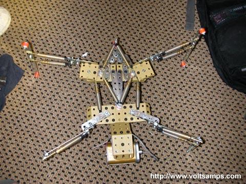
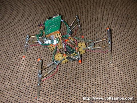
This is a top view of the robot frame with SMA actuators mounted on top. The frame was built out of an old rare erector set. As you can see the robot has many moving joints including legs and "waist".
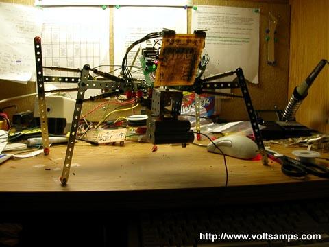
In this picture the robot was fit with a 50MHz microcontroller chip and power amplification MOSFETs. Each MOSFET has a maximum continuous current rating of 30 amps!
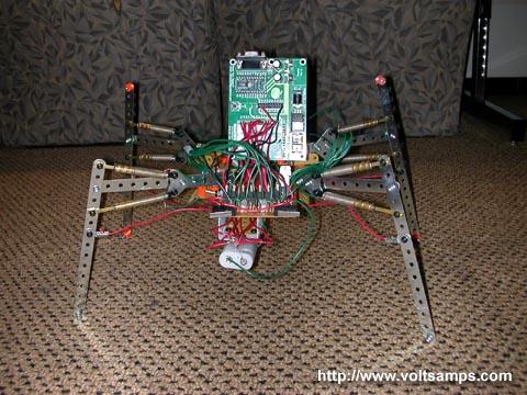
Front view of the robot showing its output bi-color LED's and bump sensors. You can also get a view of the battery pack which stores 4 NiMH AA's.
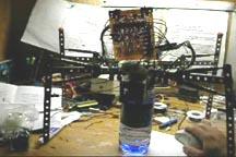
A back view of the robot shows the great number of wires which are needed to connect the actuators to the main power amplification board.
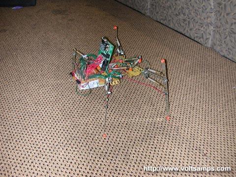
Just another side view of the robot walking on carpet.

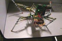
This is a picture of the robot on a smooth table top during a balance test.
Videos:
 smarobot01.mpg (2.53MB) smarobot01.mpg (2.53MB)
This is a balance test I performed to make sure the robot was able to keep balance despite the large position difference between opposite pairs of legs.
smarobot02.mpg (2.49MB)
This was a basic SMA muscle sweep test where I activated all the muscles one-by-one in order, then gave time for to thermally recover, and activated the opposing muscles to restore the limb position.
Conclusion:
After performing various tests on this robot I came to the conclusion that SMA technology isn't ready to be used in robotics quite yet. Some of the problems I encountered include high power consumption, weak actuation, heat damage, long recovery time and price. The power consumption was so high during complex movements requiring more than one muscle to contract that the battery pack melted and had to be replaced. The problem was solved with pulse width modulation (PWM) of the current; however actuation was now slower and weaker. Using high current for quick movements caused heat damage to the actuators which limited their range of motion. The recovery time was one of the other major issues. The spec sheet stated 12 seconds but this was just way to slow for a four legged robot. To sum up my results, SMA needs to be improved and for now motor and hydraulic actuators are king of robotics.
|
 |
|


 IP LOGGED: