A device referred to as the SpyFinder has recently hit the personal hidden camera locator market. This device is nothing more than a slightly modified flashlight which will locate a hidden camera via the "glint" reflected off the camera's lens. You can view the website for the SpyFinder's main distributor here: www.thespyfinder.com. It sells for $115. Really. It works by emitting an intense, pulsed beam of light from a series of red LEDs. When viewing this pulsed light source through the SpyFinder's built-in view finder, a hidden camera will show up as a pulsed reflection of light (glint) coming from the lens. That's the idea at least. It really does work, just that you'll get alot of false triggers, as anything reflective will glint. Also, modern CCD lens are getting to be very small in physical size, and it is possible to miss them if you "sweep" the area too quickly. But... If you need to quickly scan the walls in the men's bathroom during a HOPE Conference, and one of the room's tiles winks back at you, you know Emmanuel Goldstein is watching you poop.
Operating Principle
The SpyFinder hidden camera detector/locator is the most reliable and easy to use technology on the market for making sure that your private actions are not being watched. Its function is based on the principle of optical augmentation. This technical jargon refers to the phenomenon where light reflected from a focused optical system, such as a video camera, is reflected along the same path as the incident light. This means that if a hidden camera is illuminated and viewed with the SpyFinder technology, then a strong reflection from the target camera will reveal its position to the user. The SpyFinder exploits this phenomenon by using a ring of ultra-bright LEDs arranged around a viewing port. When a user scans a room looking through the viewing port, a hidden camera appearing in the field of view will brightly reflect the light from the LEDs.
Operation
While the equivalent of rocket scientists thought up the SpyFinder technology, operating it is not rocket science. Simply look through the viewing port (see photo) and depress the button to activate the LEDs. Slowly scan areas where hidden cameras are suspected and look for bright reflected spots. Remember, most hidden video cameras use pinhole camera lenses, so the spot you are looking for could be small.
If you see a suspected camera, move your vantage point slightly. If the location of the reflection moves as you move, then this is not a camera. If the location of the reflection does not move, then it is highly likely that you have discovered the optics of a hidden camera.
For example, consider a wall clock that has a domed plastic cover and a pinhole camera concealed under the numeral six on the clock face. When the SpyFinder is used to scan the clock, a reflection will be noted where the camera is located beneath the six and a reflection will also be noted from the plastic cover. However if you move your vantage point just a little, you will notice that the location of the false positive reflection point from the plastic cover will move, while the reflection from the camera remains under the numeral six on the clock face.
This version of the SpyFinder is just a simple modification to a toy "Mini Spy Scope" which is included in the Undercover Girls - Mini Spy Gadgets kit by Wild Planet Toys. I found it at a thrift store for $3. Your mileage may vary.
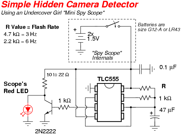
The modification consists of adding a 555-timer "pulse" circuit to the Mini Spy Scope's internal red LED. The 555-timer will pulse the red LED on and off at around six times a second (6 Hz). Also, the current to the Mini Spy Scope's LED will be decreased to around 50 mA. This will slightly decrease the LED's output optical power, but will preserve the LED's lifespan. The final modification is to remove the Mini Spy Scope's magnified viewer. The stock Mini Spy Scope had a cheap telescope-type optical viewer. It works, but since then lenses are made from plastic, the image quality is horrible, and it will drive you crazy after awhile. Another (optional) modification is the addition of a red Plexiglass filter over the eyepiece. This will help to enhance the reflected red light.
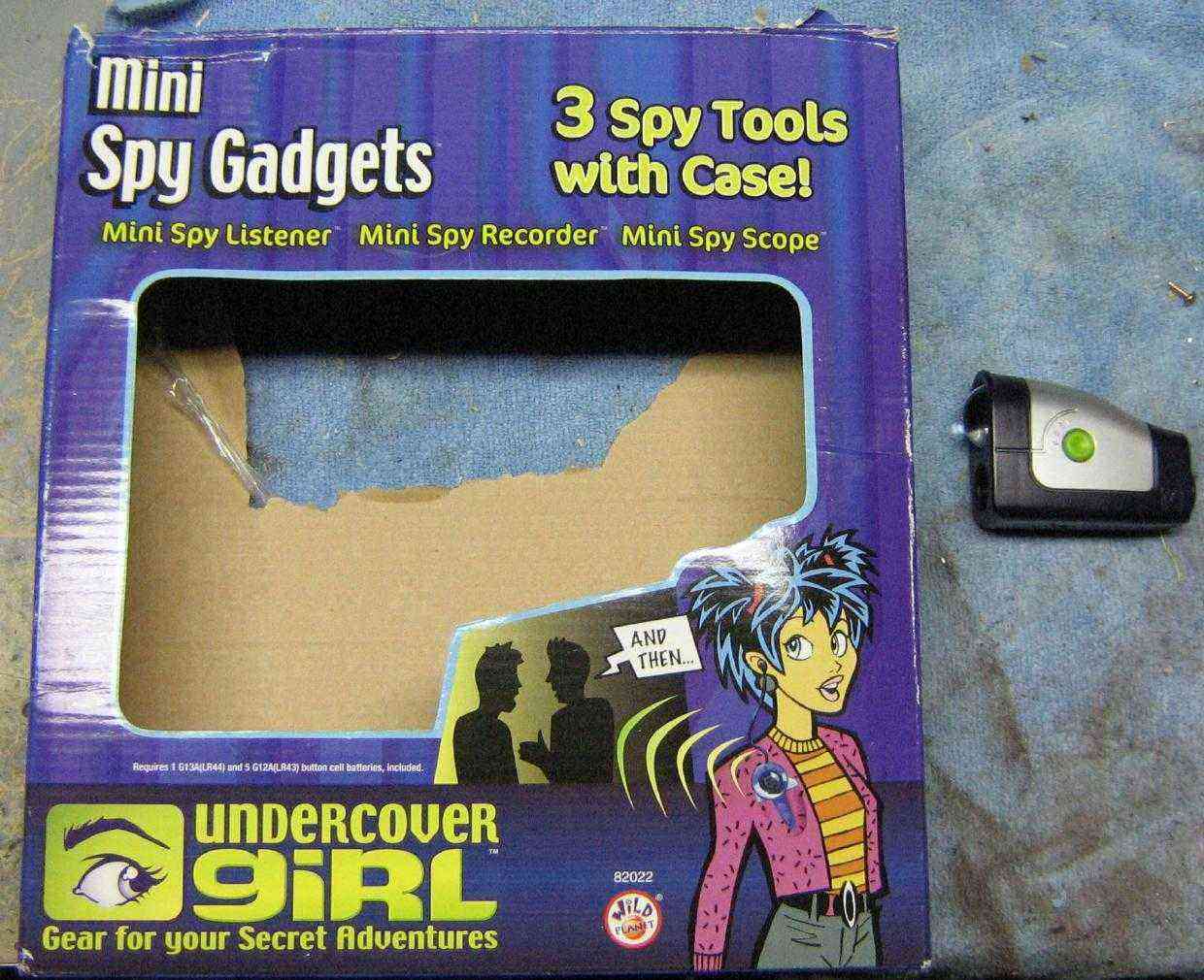
The box for the toy you'll need to look for. The unmodified "Mini Spy Scope" is shown on the right.
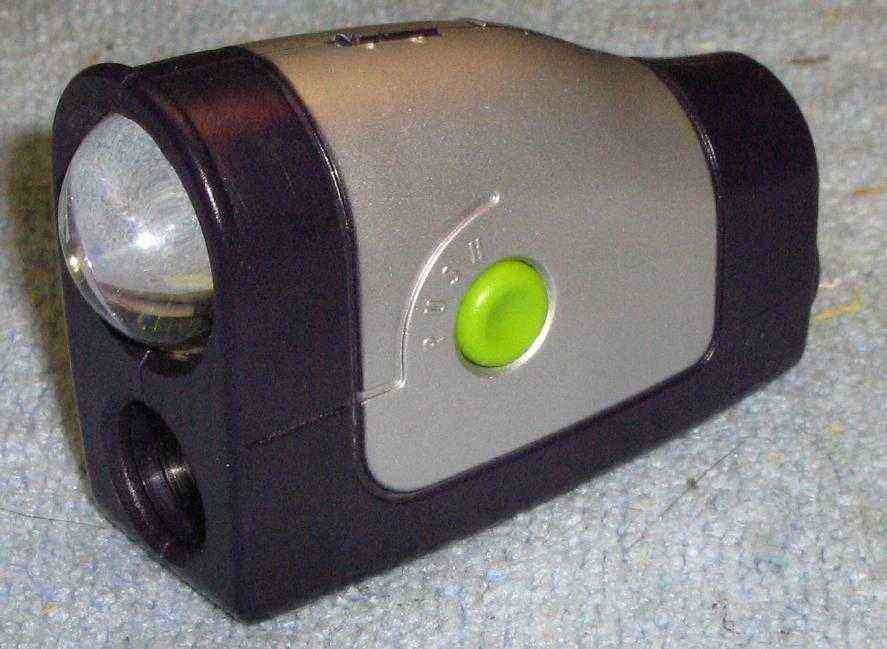
Mini Spy Scope closeup. The green button activates a red LED. The large optical lens focuses the red light into a fairly tight beam. It is powered by two 1.5V "button cell" batteries.
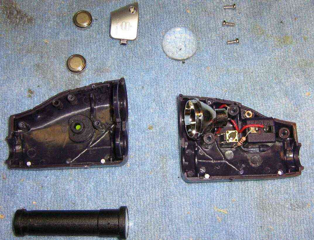
Internal view. The two batteries are on the top left. The telescope-type optical viewer is on the bottom. The main components are on the right.
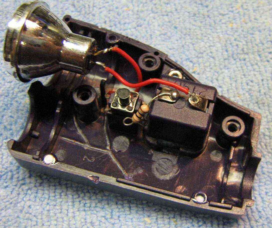
Closeup internal view. The two batteries supply +3 VDC through a series 10 ohm resistor and a push-button switch. It then goes to a red LED mounted inside a reflector cone. The stock setup ran 130 mA into the LED, which was probably designed to burn out the LED quickly so mommy or daddy would have to buy a new one. We'll drop it down to a pulsed 50 mA for this project.

The stock telescope-type optical viewer. This thing is more useless than a $2600 subscriber. Pop out the two plastic lenses, and use just the tube as the view finder.
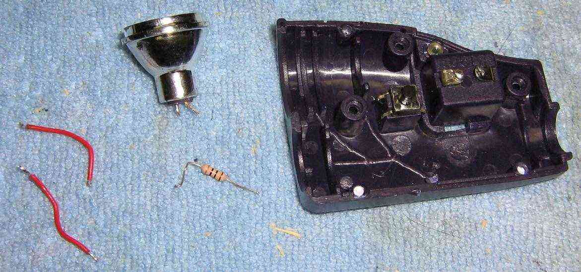
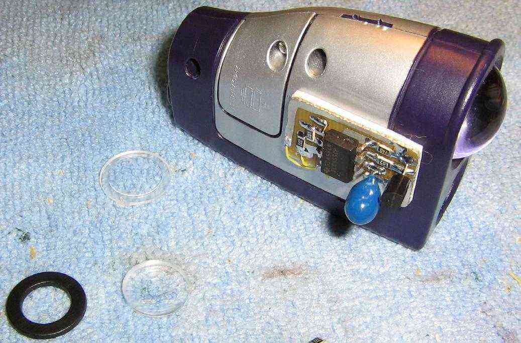
Removing the components. Be sure to remember how everything goes back together. You may also want to write down which pin is cathode (-) and anode (+) on the LED. The LED pin with only the wire is the cathode (-).
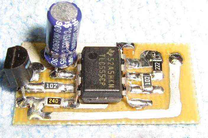
555-timer circuit you'll need to build. Be sure to use a CMOS 555-timer, as these will operate down to +2 VDC. CMOS 555-timers are available from Radio Shack (Part # 276-1718).
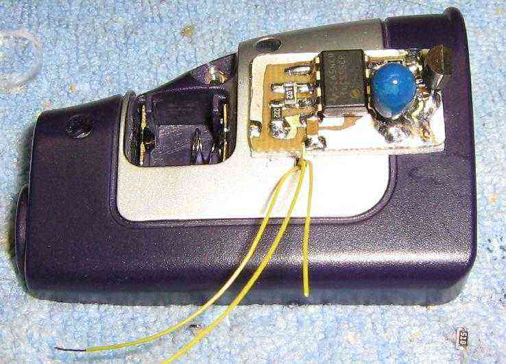
Timer circuit board mounted on the outside of the Mini Spy Scope with some double-sided foam tape. The 47 µF electrolytic capacitor was replaced with a tantalum one for reduced height.
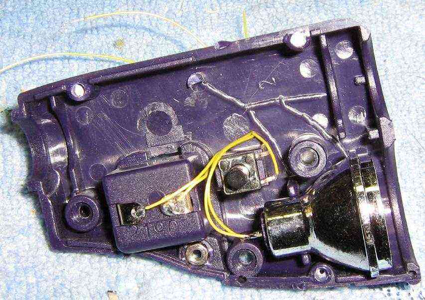
Internal wiring view.
Outside finished view. The removed lenses from the telescope optical viewer are on the left.
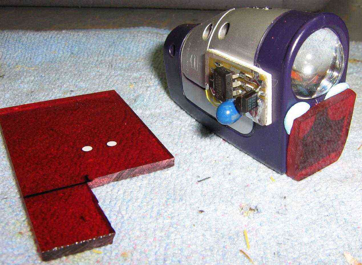
Optional red filter installed. You can find red plastic filters included with some flashlights or from the red plastic used in LED clocks. Install it using some Blu-Tac or similar poster hanging removable adhesive. This will let you quickly remove or change the filter.
Experimenters might want to look into using different polarization filters on the transmit and receive ports. Light reflected from a camera lens may change polarization. Also, you could add a PIN photodiode and automate or record the findings.
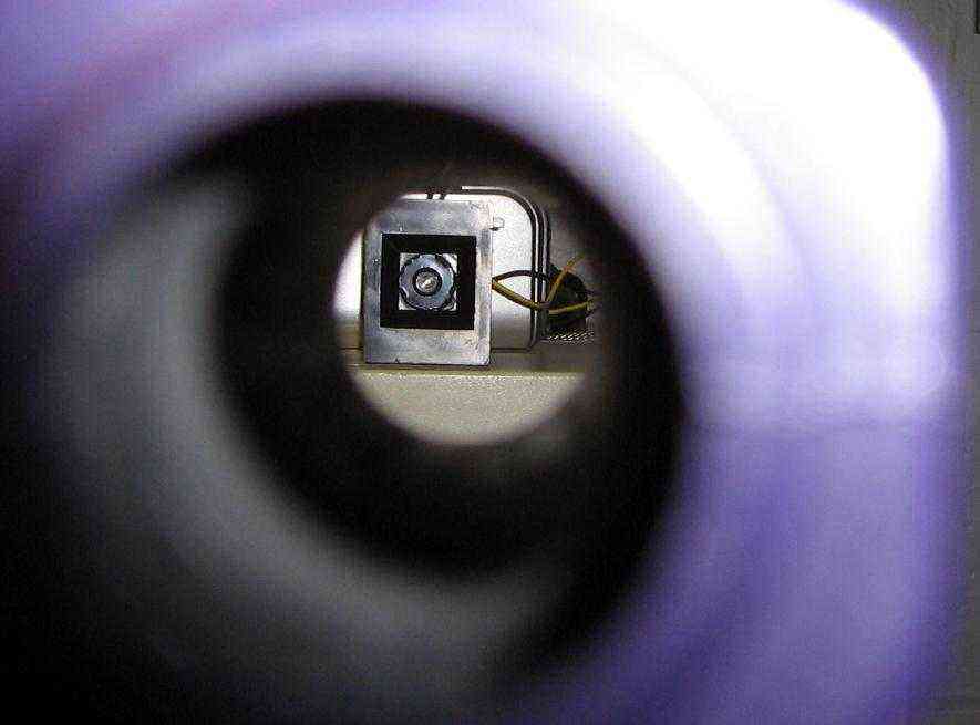
Looking through the view finder at a small video camera.
In operation. The maximum useable range is only about ten feet.
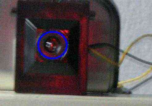
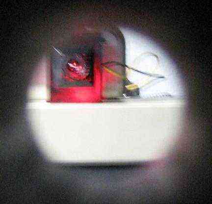
Note the tiny red pin-point. That's what you are trying to look for. It does stand out, if the background is not very reflective. Tilt your head from side-to-side to weed out false reflections. To defeat this method of camera detection, place an infrared bandpass filter ahead of your camera lens. The resulting video will not be as sharp, and you may need to use infrared LED illumination, but your camera shouldn't be detected.
To defeat that method of anti-camera detection, change the red LED in the Mini Spy Scope to an infrared LED, and view the returned pulses via a small CCD camera and TV monitor.