Overview
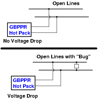
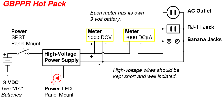
The GBPPR Hot Pack is a handy TSCM device which uses a high-voltage power source to check the integrity of any unconnected wiring. The GBPPR Hot Pack provides an approximate voltage output of 700 VDC, but with very little current. This is then connected to the device or wiring under test via some hook-up wires or an integrated outlet. Once connected, any measured reduction in voltage is an indication that there is something connected to the line or that the line is "leaking" in some way. Two internal digital multimeters measure both the voltage and current draw at the same time. Each of these meters needs to be powered via an external power source, 9 volt batteries in this case.
A good example of an item to test is a normal, everyday table lamp. When you remove the lightbulb, the wiring should show up as an "open" circuit. That is, no current should flow through the wiring. If you connect the power cord up to the GBPPR Hot Pack, and it shows a slight reduction in high-voltage output, then you know there is an "unknown" device connected in parallel with the lamp's internal wiring, or it could be the power cord is bad, you never know. Always perform a good visual overview of everthing as you perform a TSCM sweep.
Other good items to check are mechanical hook-switches inside phones, intercom/furnace/doorbell wiring, conference or boardroom speaker systems, and overhead lighting systems. All of these are targets to a potential eavesdropper.
This is also ideal for checking telephone lines. Parallel telephone taps or automatic tape recorder starters can be easily detected, even if they are positioned after a "loading coil" as some professionals will do. You will need to disconnect the telephone line from the Main Distribution Frame (MDF) at the local central office though. This can be done by using the various remote test systems (Proctor, DATU, Recent Change) or by dialing an "open termination" test number. Social engineering a frame technician is also possible.
Example
Pictures & Construction
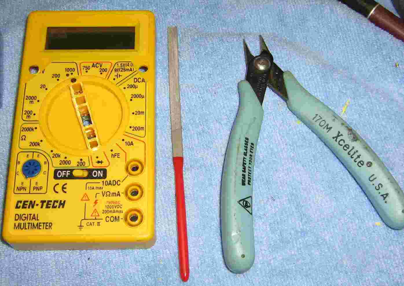
Components you'll need. The source for the high-voltage power supply will come from a Harbor Freight Tools Electronic Insect Zapper (#40122). The two Cen-Tech multimeters are also from Harbor Freight Tools (#90899). To the right of the meters are the parts needed for the outlet and also banana jacks for connecting a pair of J.S. Popper clips. A wall mounted RJ-11 telephone jack is shown to the right of the outlet plate.
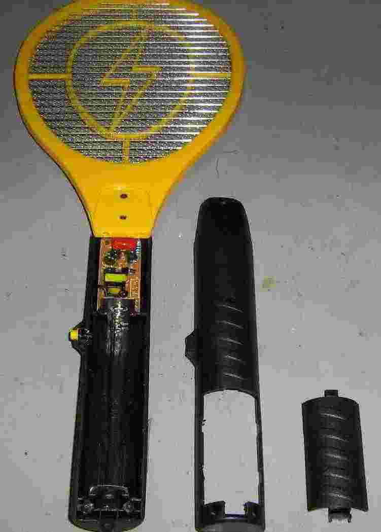
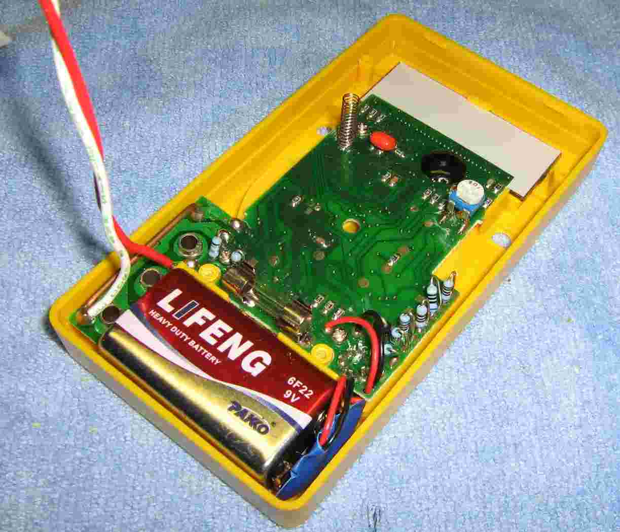
Taking the electronic insect zapper apart. It runs from two "D" size batteries. It says it generates 1,500 VDC, but its output will vary with the load under test.
High-voltage power supply mounted inside the electronic insect zapper. Be careful to note the wiring when you remove it.
The high-voltage power supply is now removed. It uses a simple DC-to-DC converter to increase the incoming 3 VDC to over 1,000 VDC. A 10 Mohm resistor across the output high-voltage capacitor will drain the capacitor when powered off to prevent getting shocked. It is also a good idea to replace the 100 ohm current-limiting resistor (the blue, 1/2 watt one) with a 10 kohm resistor. This will help to protect the high-voltage power supply from short circuits.
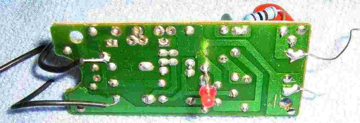
Underside of the high-voltage power supply's PC board. The top-left wire is ground, the bottom-left wire is the +3 VDC battery input. A power-indicating LED is in the middle. The high-voltage output is on the right. It shares a common ground with the DC input.
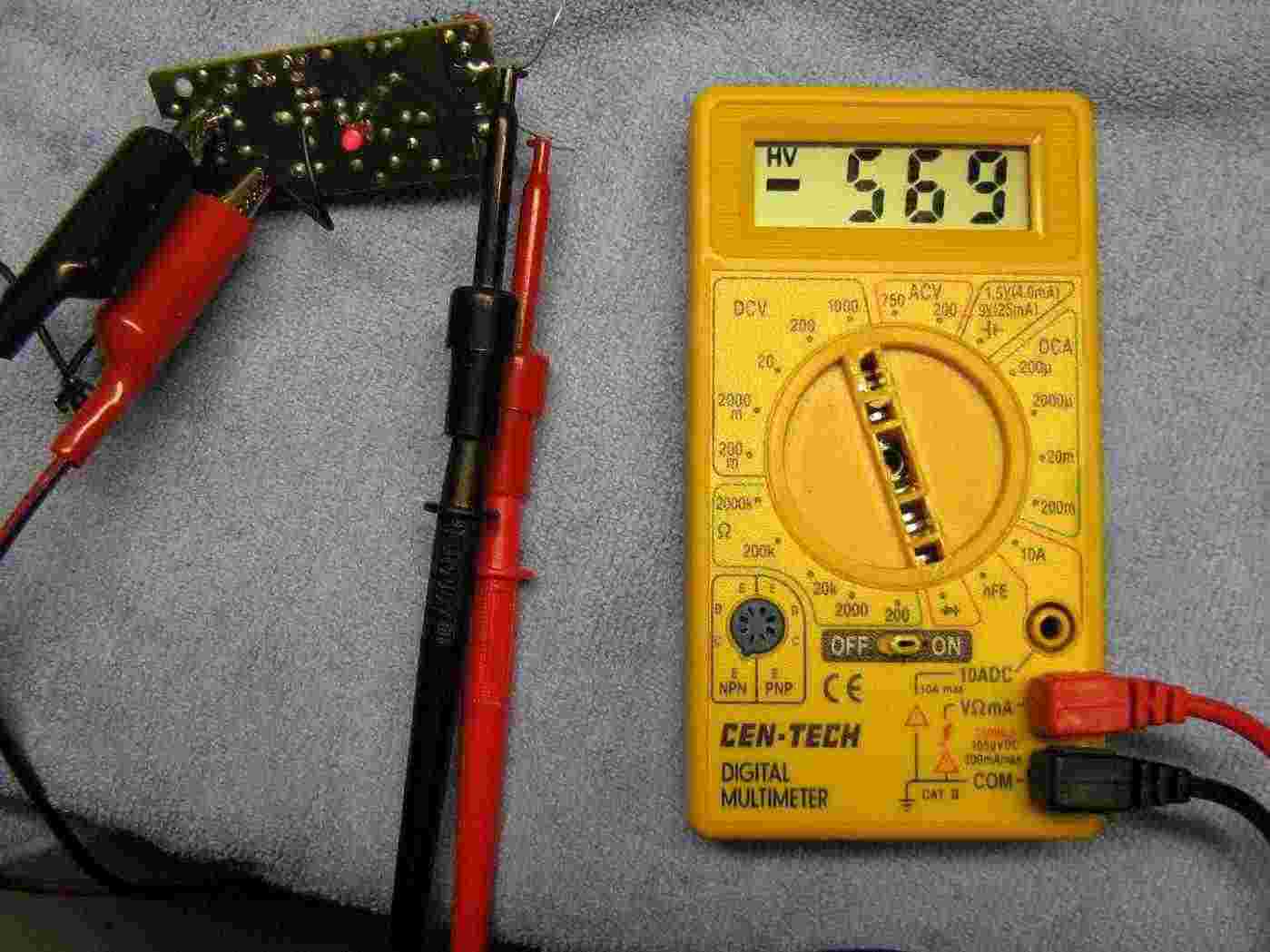
Test operation. The high-voltage output of this particular power supply when loaded with just the Cen-Tech multimeter is 569 VDC.
Now a 10 megaohm resistor is placed in parallel with the high-voltage output and the meter. It drops to 536 VDC.
Now a 1 megaohm resistor is placed in parallel with the high-voltage output and the meter. It drops even lower to 348 VDC.
As you can see, even very high-impedance "bugging" devices can be detected with this device. And as a useful bonus, the high-voltage can even destroy them, in some cases.
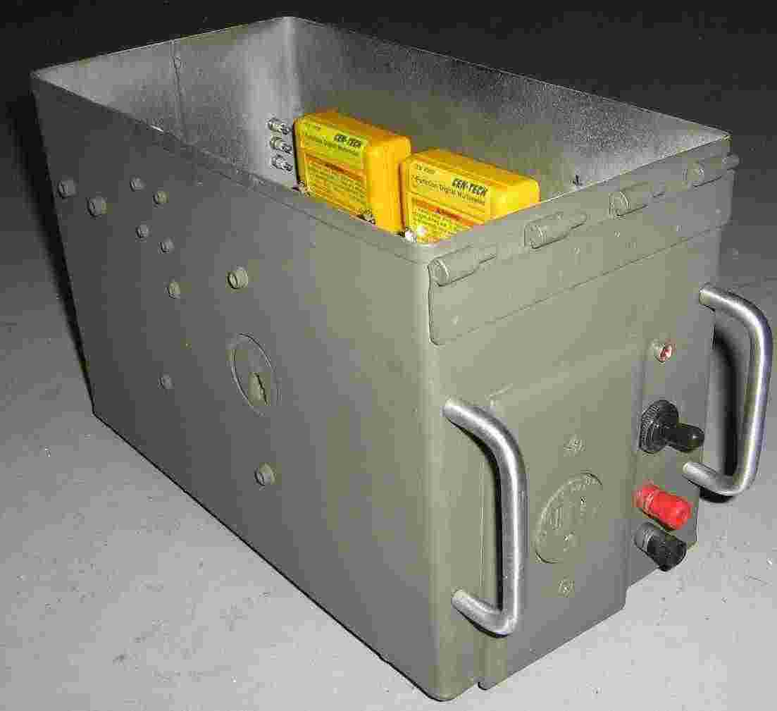
Project case overview. It's an old ammo box, as usual. The two large rectangular holes are for the meter's display and the large 1.25-inch hole (left side) is for a RJ-11 wallplate. The large cutout on the front is for an outlet box.
Preparing the digital multimeters. Two 3/16-inch holes are drilled through both plastic covers. They will be mounted to the case using two 1.5-inch long #8 screws and locking hardware. They'll need to be removable to replace the internal 9 volt batteries.
Cut and file down the large plastic selector switch on the meter's front so it can rest along the inside of the project case. Leave the on/off switch as it is.
Be sure to set (and mark) the meters to their proper ranges. The meter reading the current draw should be set to "DCA - 2000µ" and the meter reading voltage should be set to "DCV - 1000".
Inside of the meter. Solder two wires to the meter's terminals. Both the meters can be soldered in the same place. Drill a hole on the rear cover to pass the wires through.
Overview - putting everything together.
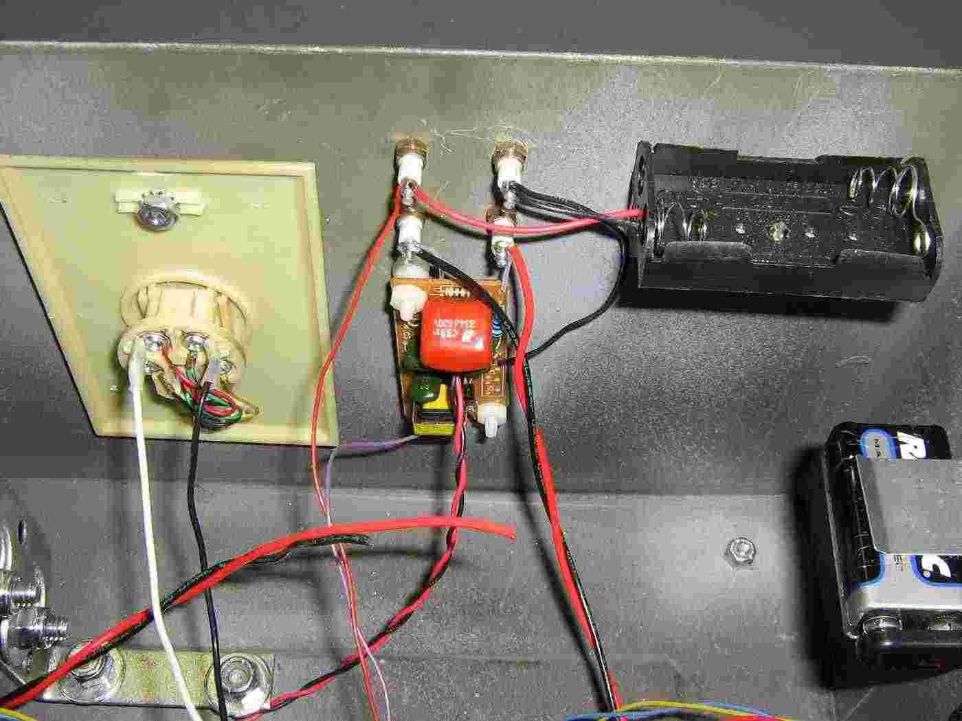
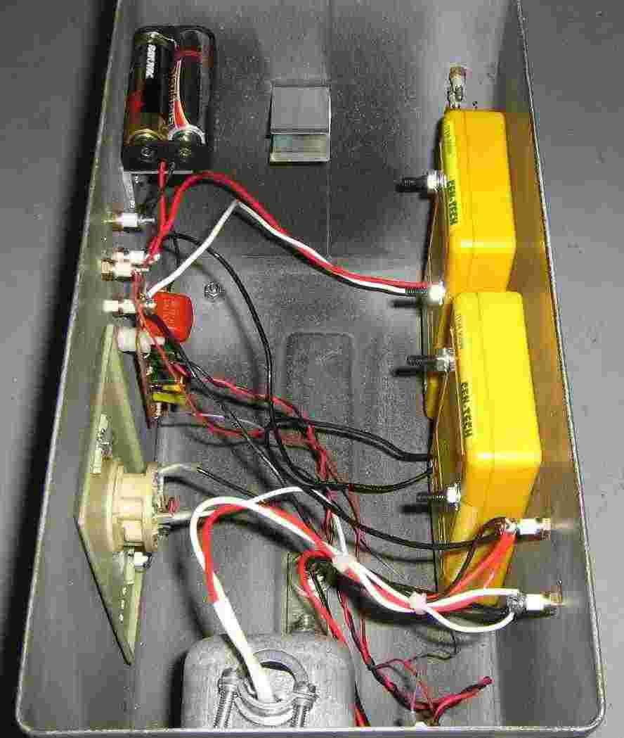
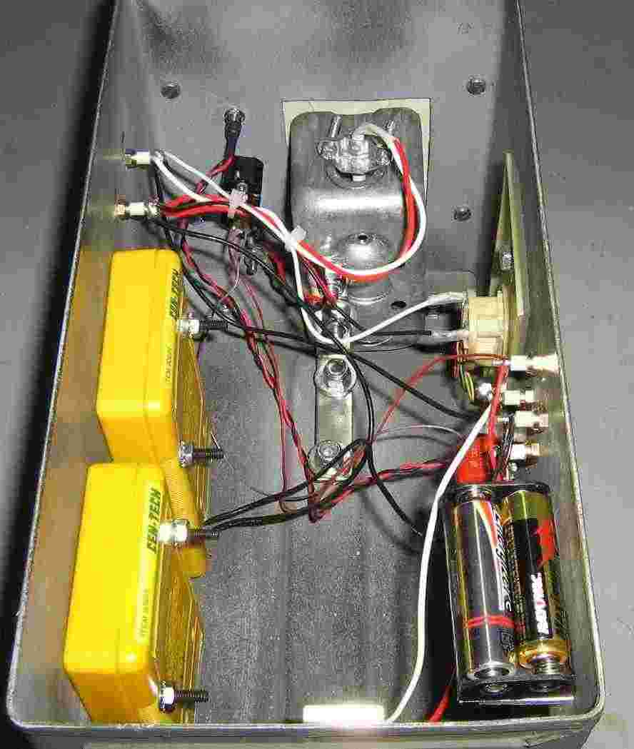
The initial version was going to have the 9 volt batteries externally mounted, but it's not worth it. The plastic battery holder on the lower-left holds two "AA" batteries to power the high-voltage power supply, which is mounted next to it. The high-voltage power supply is mounted to the case using nylon hardware. Its high-voltage output is connected to two isolation terminals. To the right of the high-voltage power supply is a RJ-11 wallplate. This provides a handy RJ-11 jack for testing phone lines. The large silver-colored metal box is a single AC outlet. This is very useful for checking disconnected (pull the fuses) AC power wiring and appliances. Underneath the power switch are two banana jacks. These are for connecting a set of "popper" alligator clips. The two isolation terminals on top are for the final high-voltage output after it passes through the two meters.
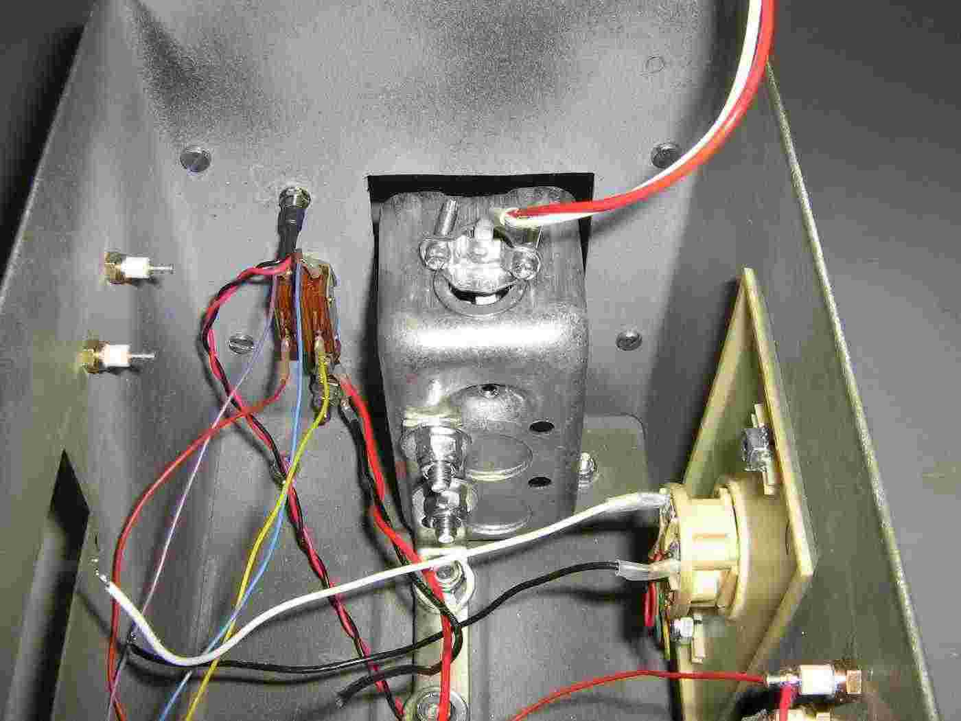
Close up picture of the high-voltage power supply and RJ-11 wallplate mounting. Teflon dielectric wiring is used for all the wires carrying high-voltage. This is optional, but helps to prevent any stray leakage current. The battery holder is mounted on a little L-bracket.
Close up picture behind the front panel.
Under construction external view.
Top view with the meters added. Two small, rectangular holes are cut on the side of the case to access the meter's power switches.
Completed top view.
Alternate view.
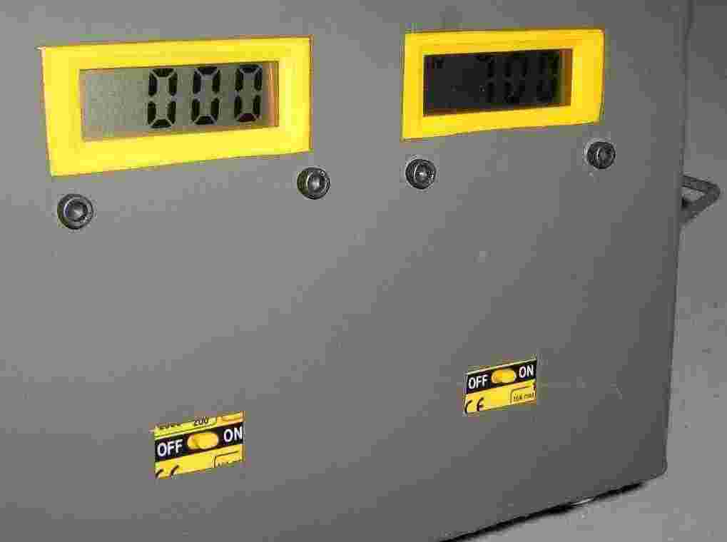
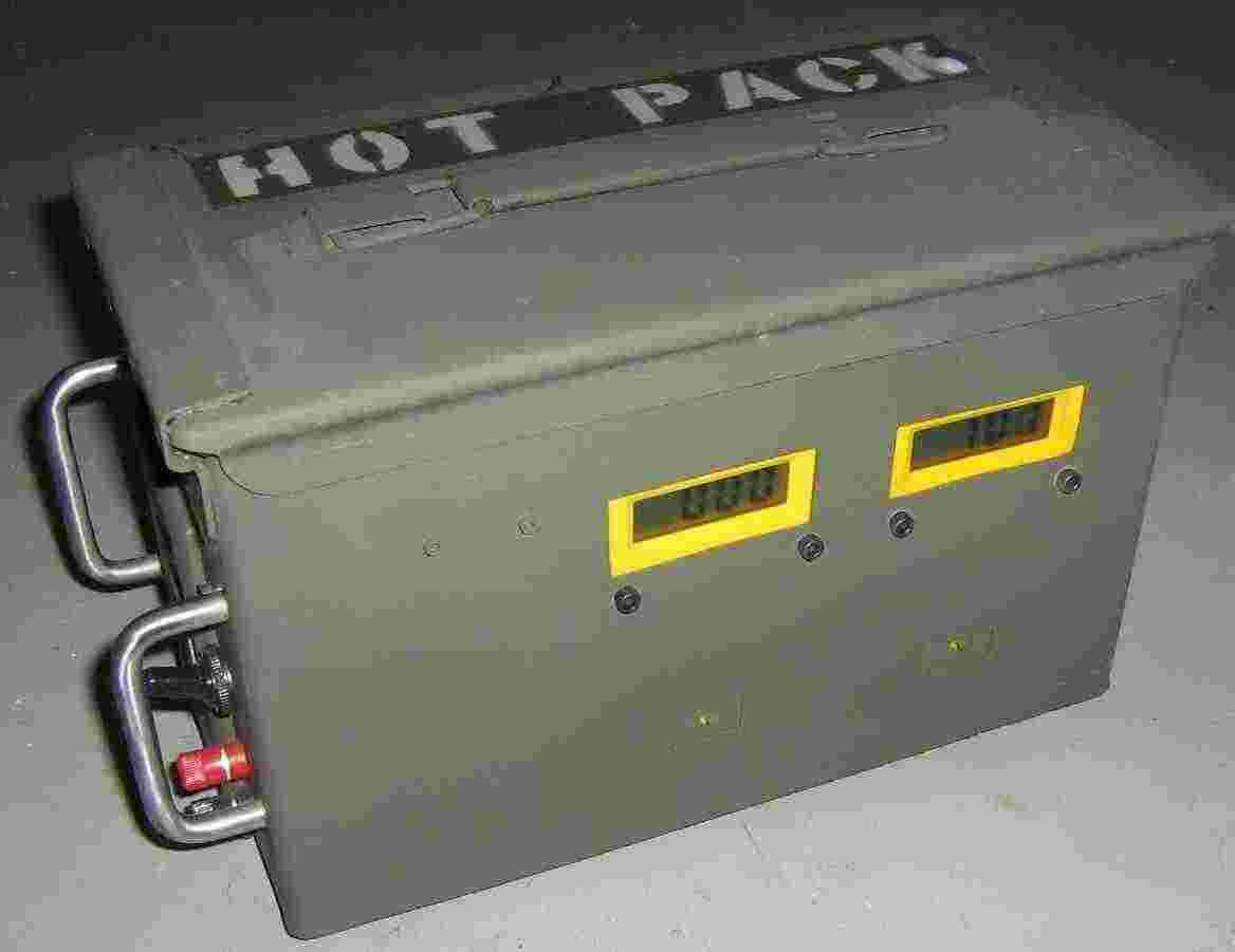
Main power is on. Meter close up picture. The meter on the left is reading the current draw (none) and the meter on the right is reading the high-voltage output (700 volts).
Completed external view. Everything is spray painted "Kill All Eurosavages" green.
Completed side view.
Accessory overview. A small AC plug-to-plug adapter is shown on the lower-left, the black square thing is a retractable RJ-11 phone extesion, and finally a set of J.S. Popper clips connected to a dual-banana plug.
Schematic


