Overview
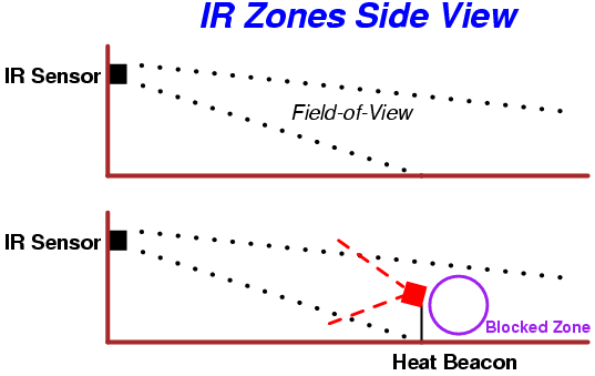
A very experimental method of using a "heat beacon" to defeat the most common type of passive infrared motion sensor. The idea is to slowly bring up a masking source of infrared radiation, using a common heat lamp in this case, to saturate the area with radiation that is close to the same wavelength as the infrared radiation emitted from a human being. Since infrared motion sensors detect the movement of a "heat" source through its field-of-view, stationary "heat" sources should not set off the sensor, but temporarily blind the sensor in that particular area. Or something like that... Does it really work? Sorta. Testing showed the theory is sound, but far from perfect for those covert black-bag operations. It is something fun to mess with, though.
The idea is, the infrared heat lamp is first placed in the "target" area to be blocked or saturated. Next, over a period of about four minutes, the heat lamp is brought up in intensity via a standard dimmer switch controlled by a stepper motor. This is to avoid creating any sudden temperature differentials which could set the motion sensor off. After a period of approximately thirty minutes (to do your work), the heat lamp will then begin to lower its output intensity. You should allow a few more minutes for the entire beacon assembly to cool down to the surrounding room temperature. Slowly remove the beacon from the area and finish covering your tracks. Do not pass in front of the beacon! At all times, move very slowly, remain very low, and always stay behind the beacon's output to avoid setting off the motion sensor.
Mounting the beacon (or beacons, you'll need several of them) on top of large Radio Controlled (RC) toy cars is a very good idea. This will allow you to properly position them from a remote location. Slap on a wireless video camera to get even more information about the target area. The heat lamp will be powered via a high-wattage AC inverter which, in turn, is connected to a high-current capable rechargeable battery. Car batteries are perfect for this application.
You may wish to experiment with using different types of lenses and mirrors to control and tweak the output beam of the heat lamp. The stock heat lamp has a very wide beamwidth, whereas this application requires a very narrow beamwidth centered directly on the motion sensor's pyroelectric sensor. However, some lenses contain coatings which block the longer wavelengths of infrared radiation. Remember, plastic lenses will melt!
How Infrared Motion Sensors Work
Stolen from the Internet. Covers the Nippon Ceramic Co. RE200B infrared sensor.
Infrared Radiation
Infrared radiation exists in the electromagnetic spectrum at a wavelength that is longer than visible light. Infrared radiation cannot be seen but it can be detected. Objects that generate heat also generate infrared radiation including animals and the human body whose radiation is strongest at a wavelength of 9.4 micrometers (µm).
Pyroelectric Sensors
The pyroelectric sensor is made of a crystalline material that generates a surface electric charge when exposed to heat in the form of infrared radiation. When the amount of radiation striking the crystal changes, the amount of charge also changes and can then be measured with a sensitive FET device built into the sensor. The sensor elements are sensitive to radiation over a wide range so a filter window is added to the TO-5 package to limit incoming radiation to the 8 to 14 µm range which is most sensitive to human body radiation.
Figure 1 shows how typically, the FET source terminal pin 2 connects through a pulldown resistor of about 100 kohms to ground and feeds into a two stage amplifier having signal conditioning circuits and a gain of 10,000 that produces a 0 to Vcc transition at its output. A well filtered power source of from 3 to 15 volts should be connected to the FET drain terminal pin 1. The amplifier is typically bandwidth limited to about 10 Hz to reject high frequency noise and is followed by a window comparator that responds to both the positive and negative transitions of the sensor output signal.
The RE200B sensor has two sensing elements connected in a voltage bucking configuration. This arrangement cancels signals caused by vibration, temperature changes and sunlight. A body passing in front of the sensor will activate first one and then the other element as shown in Figure 2 whereas other sources will affect both elements simultaneously and be cancelled. The radiation source must pass across the sensor in a horizontal direction when sensor pins 1 and 2 are on a horizontal plane so that the elements are sequentially exposed to the infrared source.
Figure 3 shows the RE200B electrical specifications and layout in its TO-5 package.
Figure 4 shows a typical application circuit that drives a relay. R16 adjusts the amount of time that RY1 remains closed after motion is detected.
Figure 1 - RE200B Block Diagram
Figure 2 - Sensor Activation
Figure 3 - RE200B Specifications
Figure 4 - RE200B Application Schematic
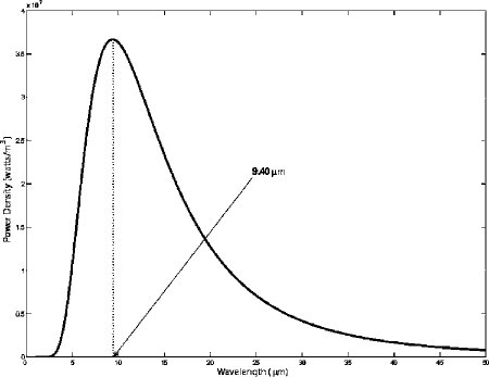
The above graph shows the blackbody radiation curve of the human body at 98.6°F. The peak emission wavelength is around 9.4 µm. Approximately 52% of the radiation power lies in the 5 to 14 µm wavelength band.
Construction
The construction of this device was mostly for fun. Significantly smaller and less complicated methods can be used to control the output of the heat lamp. A stepper motor and a dimmer switch where used in this version as they are easily available.
You'll need to take apart a standard light dimmer switch and carefully study and reverse engineer the internal components and layout. The control knob of the dimmer switch will have a little metal clip that slides along a black carbon path. This is the dimmer switch's version of a potentiometer. Measure the resistance of this path. Mine was around 250 kohms. You'll need to find a panel-mount potentiometer of that same value. If you wish, you can remove the components from the dimmer switch module and mount them on the stepper motor control board to save space.
Refer to the pictures for a basic idea on what to do with the rest of the construction and hardware mounting. Some scrap aluminum stock is used to make a mounting bracket for the stepper motor and the panel-mount potentiometer. Connect their shafts together with a coupler (or some tape). The idea is that the stepper motor will slowly turn the potentiometer in one direction, then pause a few minutes, then slowly turn back in the other direction. The new panel-mount potentiometer is used in place of the stock potentiometer on the dimmer switch's circuit board. If everything goes right, and it will need alot of tweaking, the heat lamp should increase and then decrease in intensity via the stepper motor controlled potentiometer. If it does this backwards, you wired the potentiometer wrong!
The salvaged stepper motor (I have no idea where I found it) used in this particular project is labeled:
COPAL ELECTRA STEP MOTOR SP-57
12V / 36 ohm / 7.5°
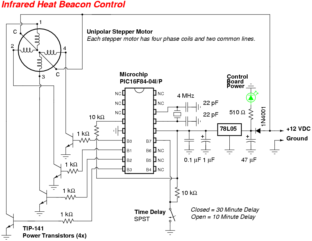
The 12V refers to the maximum phase coil winding voltage and the 36 ohms is the windings resistance. Current draw per phase coil is around 300 mA, or 600 mA total for each step. The stepper motor also gets 7.5° of turn per step. So it would take 48 steps to do a complete 360° revolution. For controlling a panel-mount potentiometer, you'll need around 44 steps, or about 330° of revolution.
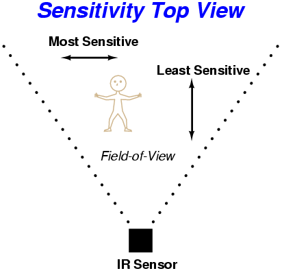
Several of these beacons should then be mounted to radio controlled toy trucks and remotely pre-positioned in front of the motion sensor to create a "shadow" zone which a human being could operate in. It should be noted that infrared motion sensors have maximum sensitivity to movement across (parallel) their field-of-view and minimum sensitivity to any movement towards (perpendicular) the sensor's field-of-view. Always try to plan your attack route to slowly move towards the sensor when crossing its path. Longer, safer routes are much better than short, dangerous routes.
| Stepper Motor Truth Table |
| Phase Coil |
16F84 Port |
Binary Value |
Decimal Value |
| 4 |
B0 |
0001 |
1 |
| 2 |
B1 |
0010 |
2 |
| 3 |
B2 |
0100 |
4 |
| 1 |
B3 |
1000 |
8 |
To "step" the motor, you need to activate two of the four phase coils in a particular sequence shown below:
| Stepper Motor Operation - Clockwise |
| Motor Step |
Phase Coil 1 |
Phase Coil 2 |
Phase Coil 3 |
Phase Coil 4 |
| 1 |
ON |
OFF |
ON |
OFF |
| 2 |
OFF |
ON |
ON |
OFF |
| 3 |
OFF |
ON |
OFF |
ON |
| 4 |
ON |
OFF |
OFF |
ON |
By viewing the two above tables, we can see that we need the four ports on the 16F84 to output a continuous binary value of 1100, 0110, 0011, 1001 for a clockwise operation of the stepper motor. In decimal that would be: 12, 6, 3, 9. It's kinda confusing, so study that a bit. Reverse this sequence to reverse the stepping action: 9, 3, 6, 12.
Pictures
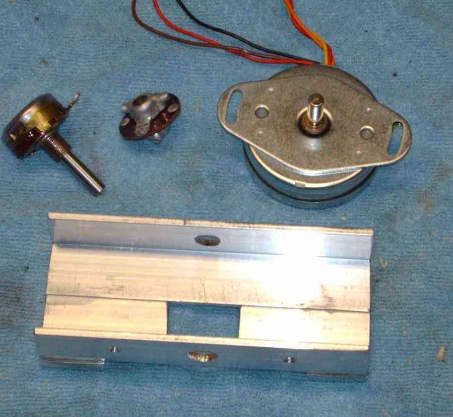
Overview of the stepper motor, dimmer switch control potentiometer (250 kohms), the shaft coupler, and right-angle aluminum stock to mount everything on. The aluminum pieces are epoxied together which makes construction very simple. The large cutout is for the shaft coupler.
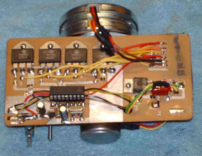
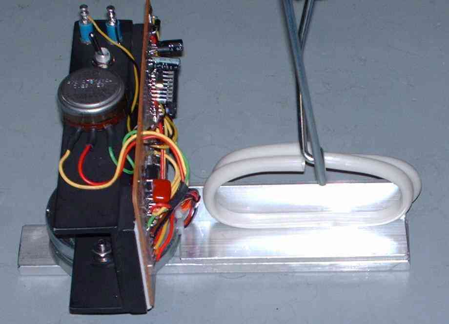
Stepper motor control board. A Microchip PIC16F84 controls four TIP-141 darlington transistors which, in turn, control the phase coils of the stepper motor. The components on the lower left are from a dimmer switch. The dimmer switch's components where removed from the switch housing and mounted on the PC board. Note the six wires for the stepper motor. Each stator cup has three wires, two for the phase coils and a common. The unipolar stepper motor is actually made up of two motors connected together.

Overview of the stepper motor control for the dimmer switch's control potentiometer.

Another overview. The two terminal posts where added for the control board's +12 VDC and GROUND wires. The switch controls the time delay before the heat lamp begins lowering its intensity.
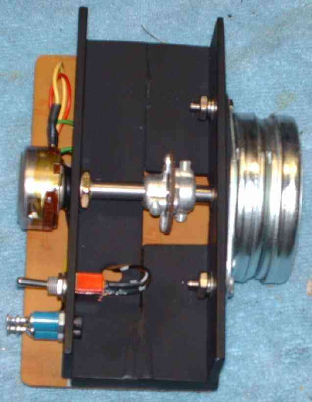
Side view. Note the rubber O-ring for the potentiometer. This allows a little bit of "play" for the potentiometer's shaft to meet the coupler, in case it doesn't properly line up.
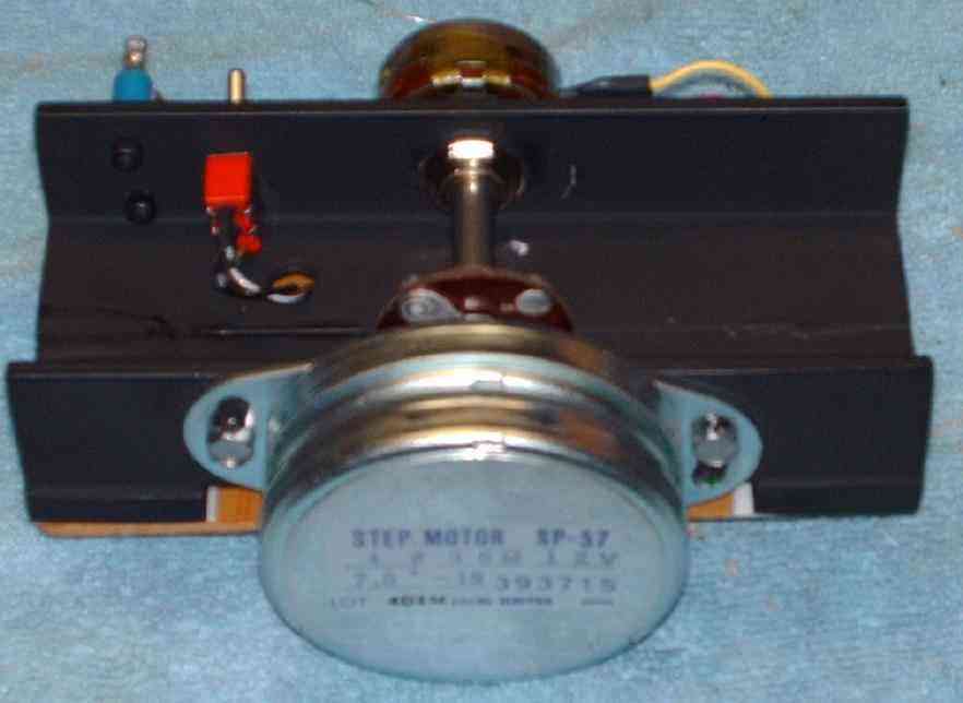
Rear view of the stepper motor.
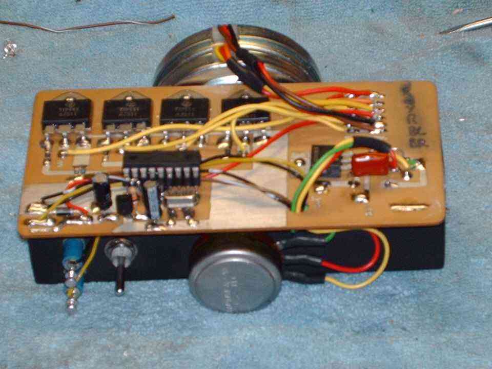
Completed beacon control board. The two large solder pads on the left are for the AC input to the light dimmer control.
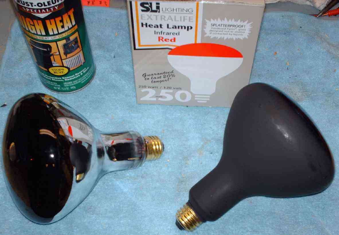
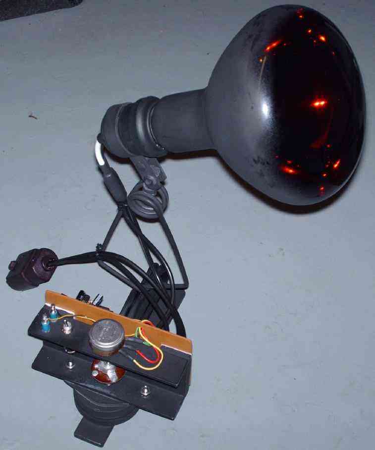
Overview of the infrared heat lamps used. A stock one is on the left. High-temperature, black grill/stove paint is used on the back of the lamps to prevent any light from seeping through (there is alot). It also prevents the lamp from being easily seen.

Hardware from a common clip-on lamp holder, minus the reflector, will be used to position the heat lamp.
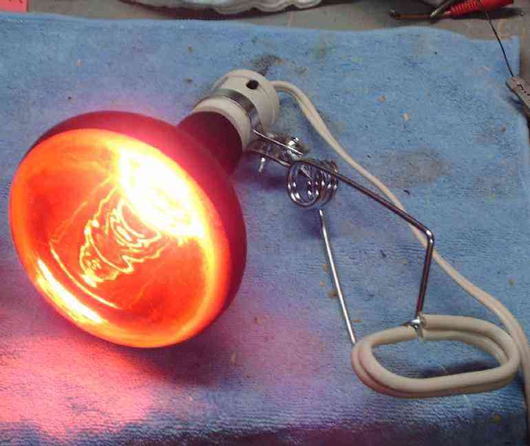
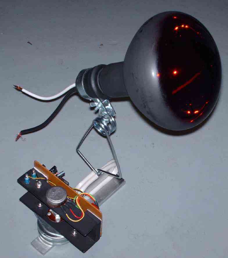
Heat lamp in operation. The visible output is a deep red.
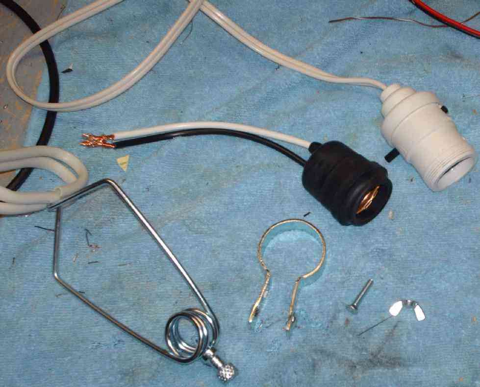
I found a neat little black rubber lamp socket at the hardware store. This will replace the stock socket on the clip-on lamp holder.
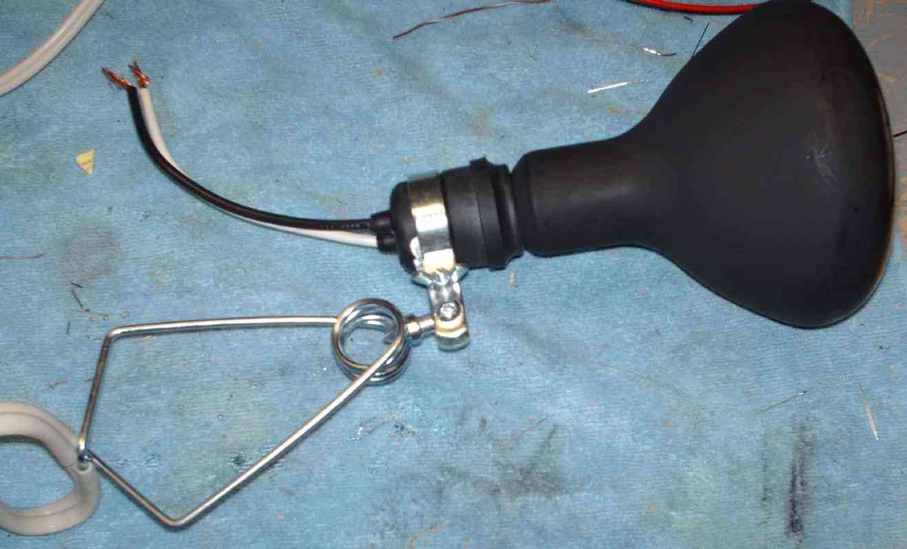
This is what the lamp holder should look like when finished.
Test setup. The clip-on lamp holder is attached to a piece of right-angle aluminum.
Closeup picture of the clip-on holder and the angle bracket.
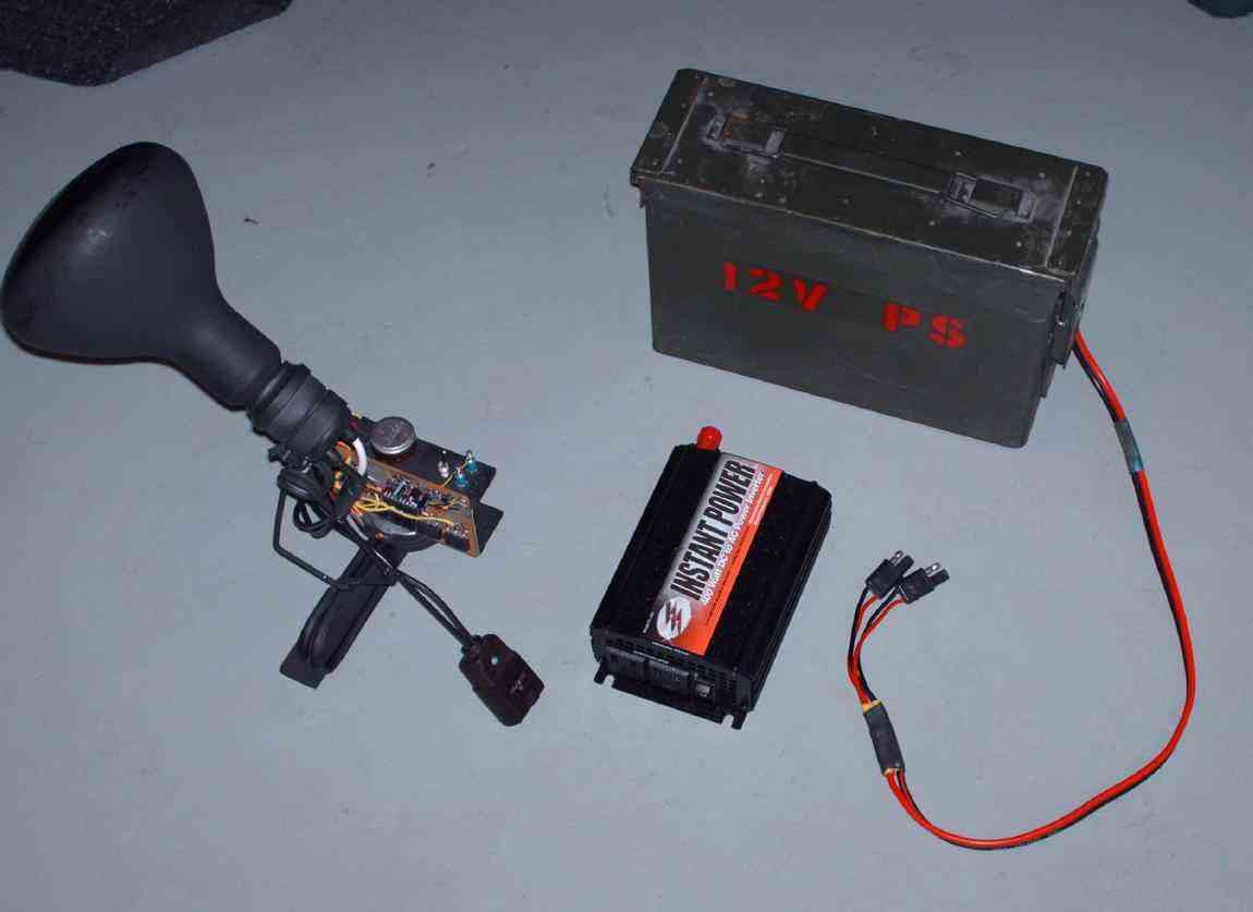
Experimental test setup. The ammo box contains a large 12 volt lead-acid battery. This will power both the beacon's control board and a 400 watt AC inverter. The AC inverter shown in the picture is a piece of junk, and only sources around 250 watts continuous. Get a good 800 watt or larger AC inverter to avoid any problems with long lamp run times. Run power to the beacon and lamp using two runs of 2-conductor "zip" wire.
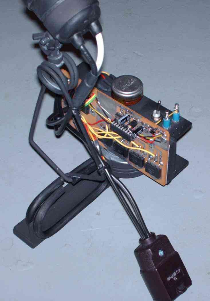
Close up of the completed beacon. The cord and socket are for the lamp's AC voltage. The AC power cable goes through the dimmer switch controller then onto the heat lamp.
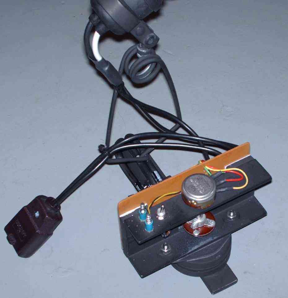
Side view.
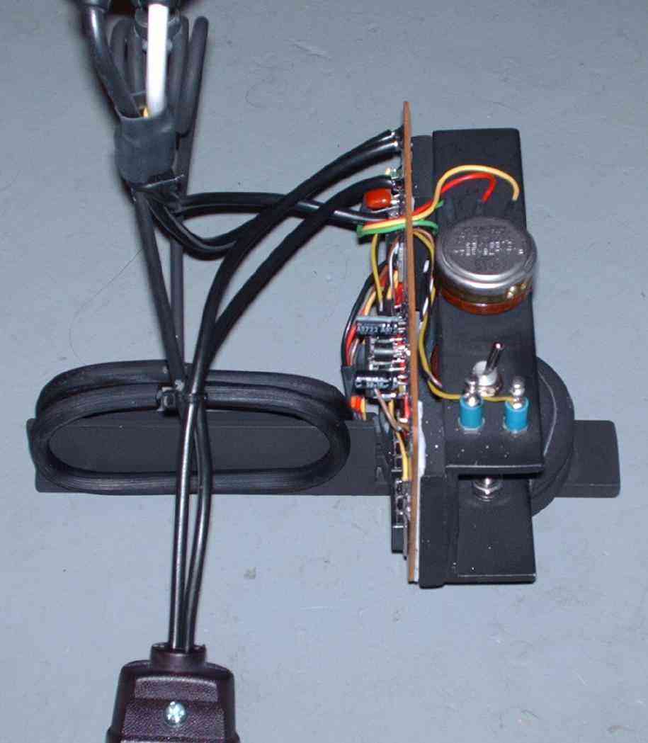
Rear view.
Completed infrared beacon. The flat black paint really reduces the overall visibility of the beacon.
Operational Diagrams
Schematic and Source Code
Links & Notes