Laser Snooper
 Introduction:
This project was based on the project by Chuck Clark and Sam Ralston last Fall.
I have been interested by this project when I saw this in the ADSL Open House.
I also noticed that their project didn't work. I remembered that I have seen
something like this on TV on one of those shows devoted to science and technology.
They were showing how intelligence/reconnaissance has turned to laser for
information gathering - or more accurately, eaves dropping.
After looking at the Fall's semester's design I decided to start from scratch. I had an alternative design in mind which I have found from an electronic hobby enthusiast magazine. Here's the design of the circuit and the step down transformer for the audio device.
Project Goal:
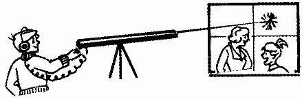
By reflecting any type of laser (with no modification of the emitted light)
off of a thin media (like a window plane) the Laser Snooper is to capture the
reflected beam. The reflected beam is modulated by the vibrations in the pane
from noises on the other side of the window. The receiver detects this
modulation and reconstructs the noises and conversations. Also, the device in
mind was made with parts that are very cheap and easily obtainable.
The Circuit:
In this circuit, the design achieved the objectives of reconstructing the
reflected laser beam into real sounds via an audio output port
(HEADPHONE JACK). The design also included a way of detecting
(METER JACK) the strength of the laser signal received. This
was to be used to align the receiver should an invisible laser beam was used.
But the device connected to detect the signal is a separate piece of equipment
that wasn't used in this project since a visible bright red Helium Neon laser
was used.
CIRCUIT THEORY:
The heart of the circuit is a sensitive photo transistor (Q1). Varying light
levels across R2 produce a changing voltage level at (Q1) collector that is
capacitively coupled thru (C4) to the base of preamplifier transistor (Q2).
Resistor R3 bias the base and sets the gain of Q2. Emitter bias is obtained
via R5 with signal current being bypassed by C5. The above combination provides
a voltage gain of approximately 40 for this stage. The amplified signal is
developed across R4 and is capacitively coupled by C7 to gain control pot R6.
Capacitor C6 and C9 stabilizes the circuit by bypassing any unwanted oscillations
that could occur. The arm of R6 is now capacitively coupled by C8 to the base
of Q3. The gain of this second amplifier to 40 by resistor R8 and R10.
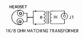
Output of Q3 is capacitively coupled to Q4 by C11. The gain of this stage is set to 40 by resistors R13 and R14. R12 provides a small amount of degenerative feedback for the system. Output of Q4 is capacitively coupled by C13 to output jack J1 for driving earphone as shown in the schematic printout. Output is intended to couple to a 1000 to 8 ohm step-down audio transformer. The 8 ohm winding drive standard 8 ohm monophonic headsets or a small speaker. The output of Q4 is also coupled to amplifier Q5 via capacitor C12. This stage has a gain of x10 set by resistors R15 and R16. The output is now rectified and integrated onto capacitor C15 and C16. This DC level drives external meter via jack J2. Resistor R7 limits output current to 1/2 mAmps.
Use the chart below as a guide to see if the circuit is working properly.
| Battery | A | B | C | D | E |
| 9V | .5DC | 4.5DC | 3.3DC | 1.1DC | 6DC |
NOTES:
Factors Affecting the Design:
First, make sure, when building the circuit, the parts are of exact values.
In my first circuit, the resistors were of approximate values and the circuit
left all sorts of cut-off currents disabling the circuit. Going by the bands
and printed values on the parts are sufficient.
Second, I have found that when the receiver was centered in the brightest spot
(middle) of the reflected laser beam the circuit worked poorly compared to when
the receiver was placed off-centered. This probably indicated that the circuit
was saturated when the receiver was centered. And when it was off-centered,
the circuit was able to analyze the weaker (less saturated) laser signal better.
This must show that the lower energized beam was better able to become modulated
when the beam was contacting the sound source.
This can be useful in that this can mean that the laser can be sent at a longer
distant to work even better. And the thickness of the plane where the sound
source is found can also affect the performance of the receivers capability to
detect any changes in the signal. The thinner the plane, the easier it will
vibrate and the better for the laser to be come modulated.
Future Design Considerations:
Although it was said that the greater the distance the laser and the sound source
the better the chance the laser will diverge larger giving a weaker signal (which
prevents the over-saturation of the circuit) there will come limitations to this
process.
So, using lenses to converge a larger area of the reflected beam to the receiver will help increase the range of the laser snooper even more. It was printed that the range may be as large as 300 feet versus the current 30 feet range. Although this isn't really an electronic project, one way to think about as a future design is to implement Jake Janovetz's Napoleon 56K DSP board to filter out background noise. Background noise was very present from the receiver, and using the DSP board might have helped out in making the receiver work even better than it was designed for.
Conclusion:
This project has helped me relearn the theories learned from ECE342.
Transistors were used to bias currents yielding different voltage levels.
And capacitors were used to couple points of the circuit to stabilize.
Not only did this project help teach some fundamentals of circuit theory,
but it was fun to work on and see the results of the project.
R1			1	100 Meg 1/2 Watt Resistor
R2,4,10,15		4	10 K 1/4 Watt Resistor
R3,8			2	390 K 1/4 Watt Resistor
R5,14,16		3	1K 1/4 Watt Resistor
R6/S1			1	10 K Pot and 12 V Switch
R7			1	2.2 K 1/4 Watt Resistor
R12			1	5.6 Meg 1/4 Watt Resistor
R13			1	39 K 1/4 Watt Resistor
R17			1	22 K 1/4 Watt Resistor
R9,11			2	220 Ohm 1/4 Watt Resistor

C1			1	470 Pfd Disc Cap
C2,10			2	100 Mfd 25 V Elect Cap
C3,9			2	1000 Pfd Disc Cap
C4			1	.05 Mfd Mylar Cap
C5			1	10 Mfd 25 V Elect Cap
C6			1	.01 Mfd 25 V Disc Cap
C7,8,11,12,13,14	6	2.2 Mfd 25 V N.P. Cap
C15,16			2	1 Mfd 25 V Elect Cap

Q1			1	L14G3 Ultra High Sen Phototransistor
Q2,3,4,5		4	PN222 NPN Transistor
D1,2			2	IN914 Diode

J1			1	RCA Phono Jack
P1			1	RCA Phono Plug
CL1			1	9 V Battery Clip
T1			1	1 K / 8 Ohm Mini Audo Transformer