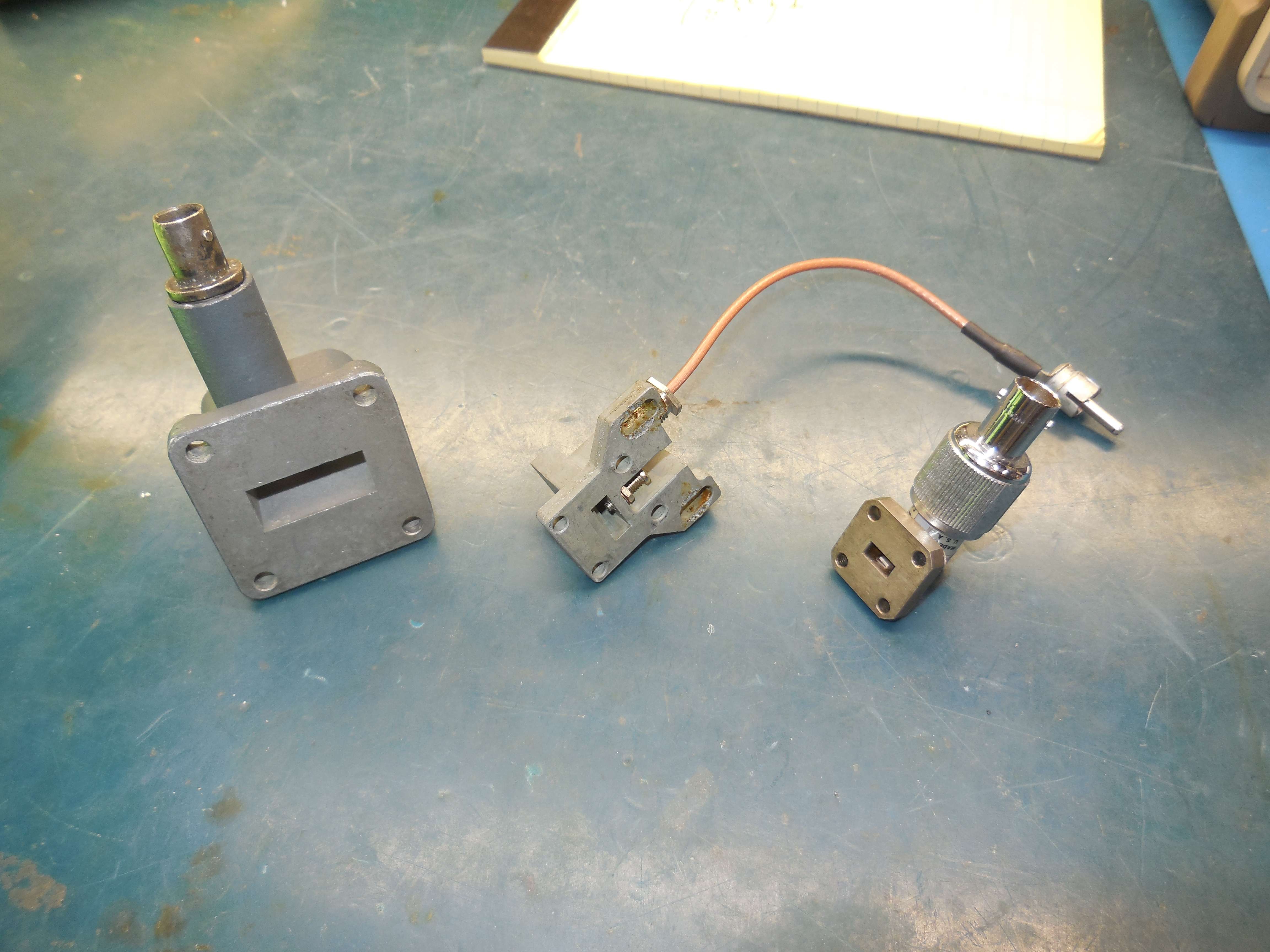
Example of proper commercial waveguide diode detectors/mixers.
WR-90 (X-band) on the left, WR-42 (K-band, from an old radar gun) in the middle, WR-28 (Ka-band) on the right.
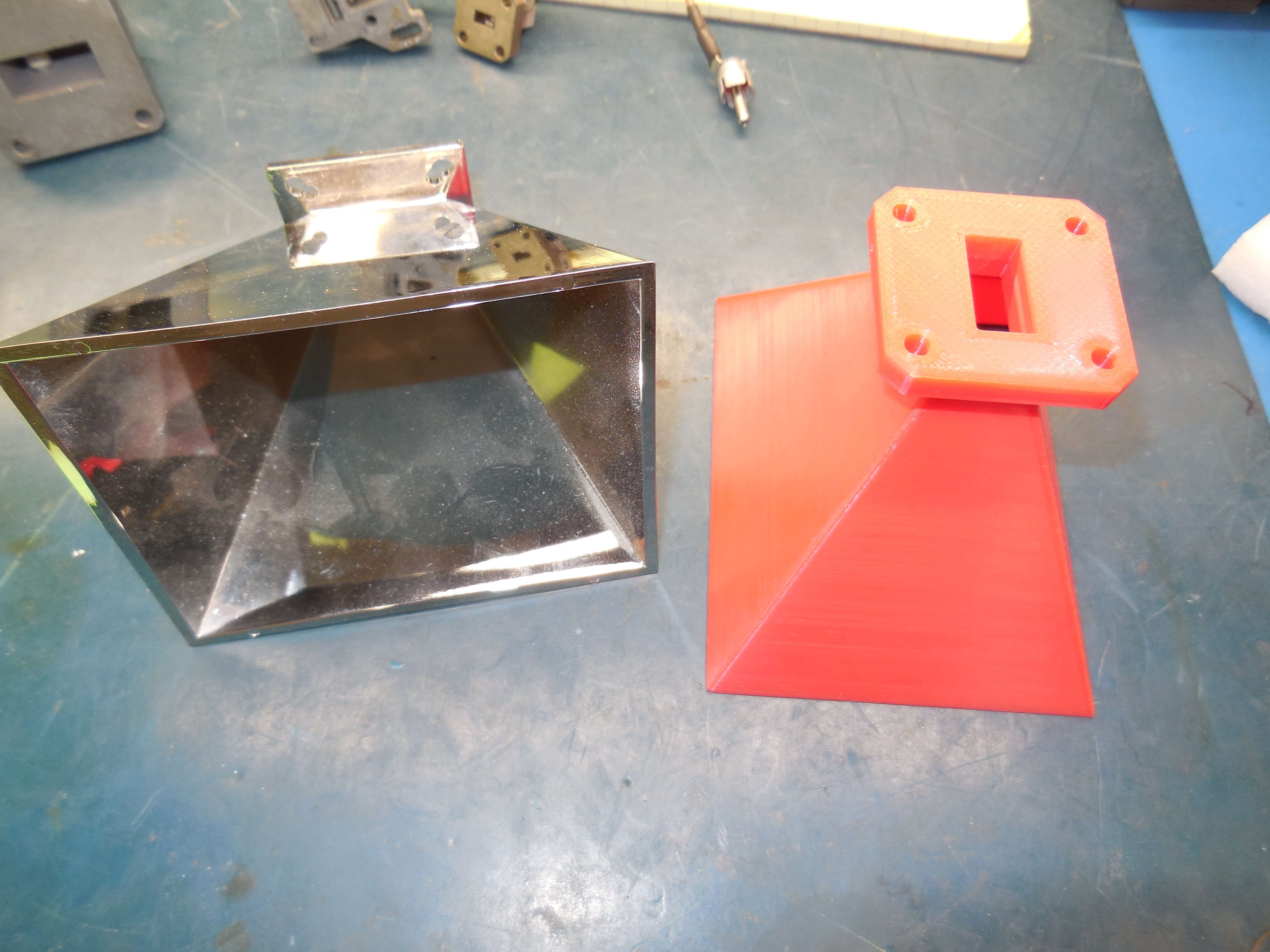
Plastic horn antennas.
A commercial one is on the left, a 3D printed one is on the right.
The 3D printed one will need to be coated with a conduction spray paint.
This can be handy for hiding from metal detectors.
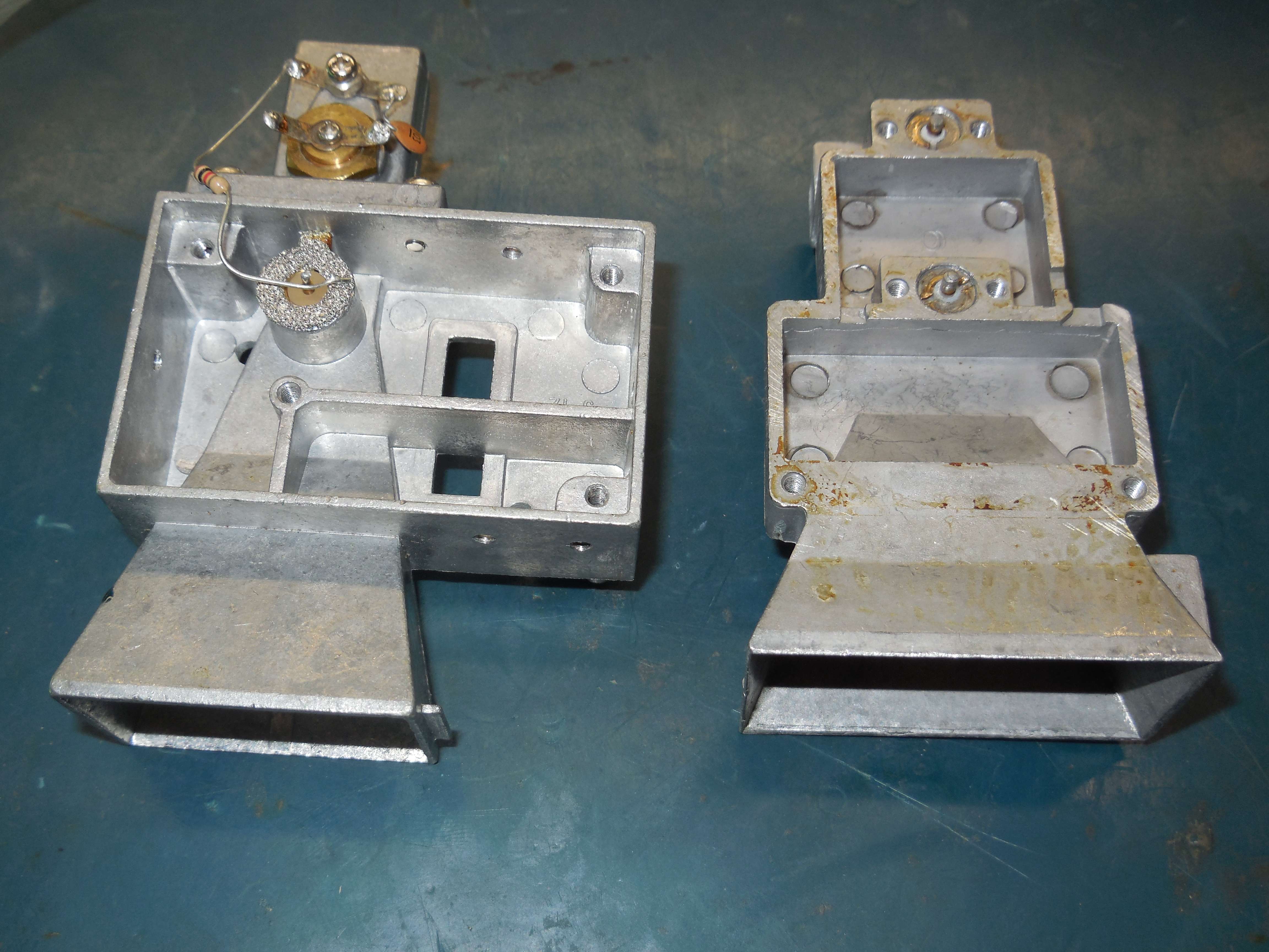
Example of two modern X/K/Ka-band radar detectors.
The "rear" connection is usually a Gunn diode mounted in a cavity used for the local oscillator frequency (usually around 11.5 GHz). The "front" connection is usually a mixer diode used for the IF output.
Bottom view of the detectors. The screws are used for tuning.
Looking down the horn of a modern radar detector showing the Schottky diode up font.
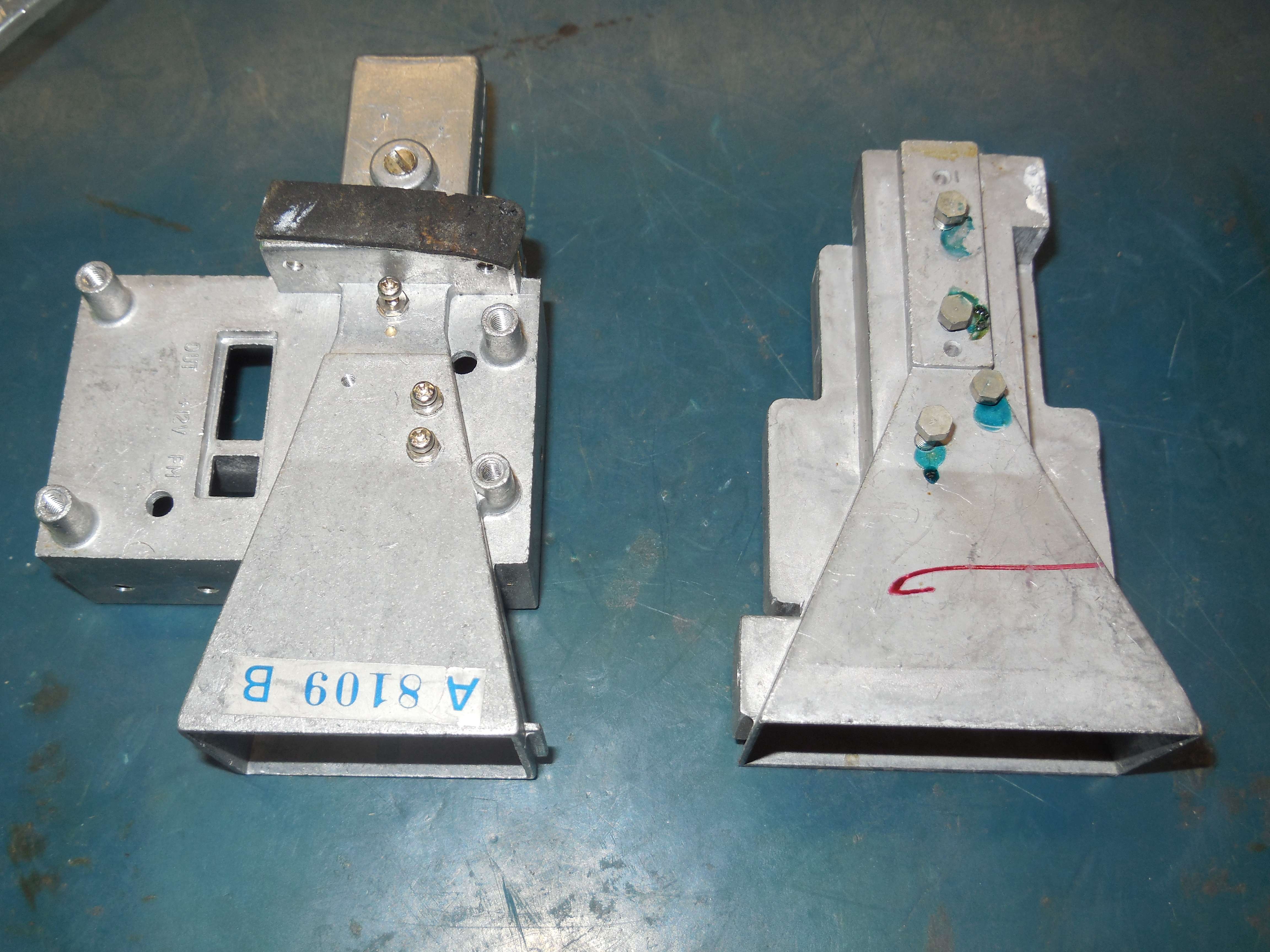
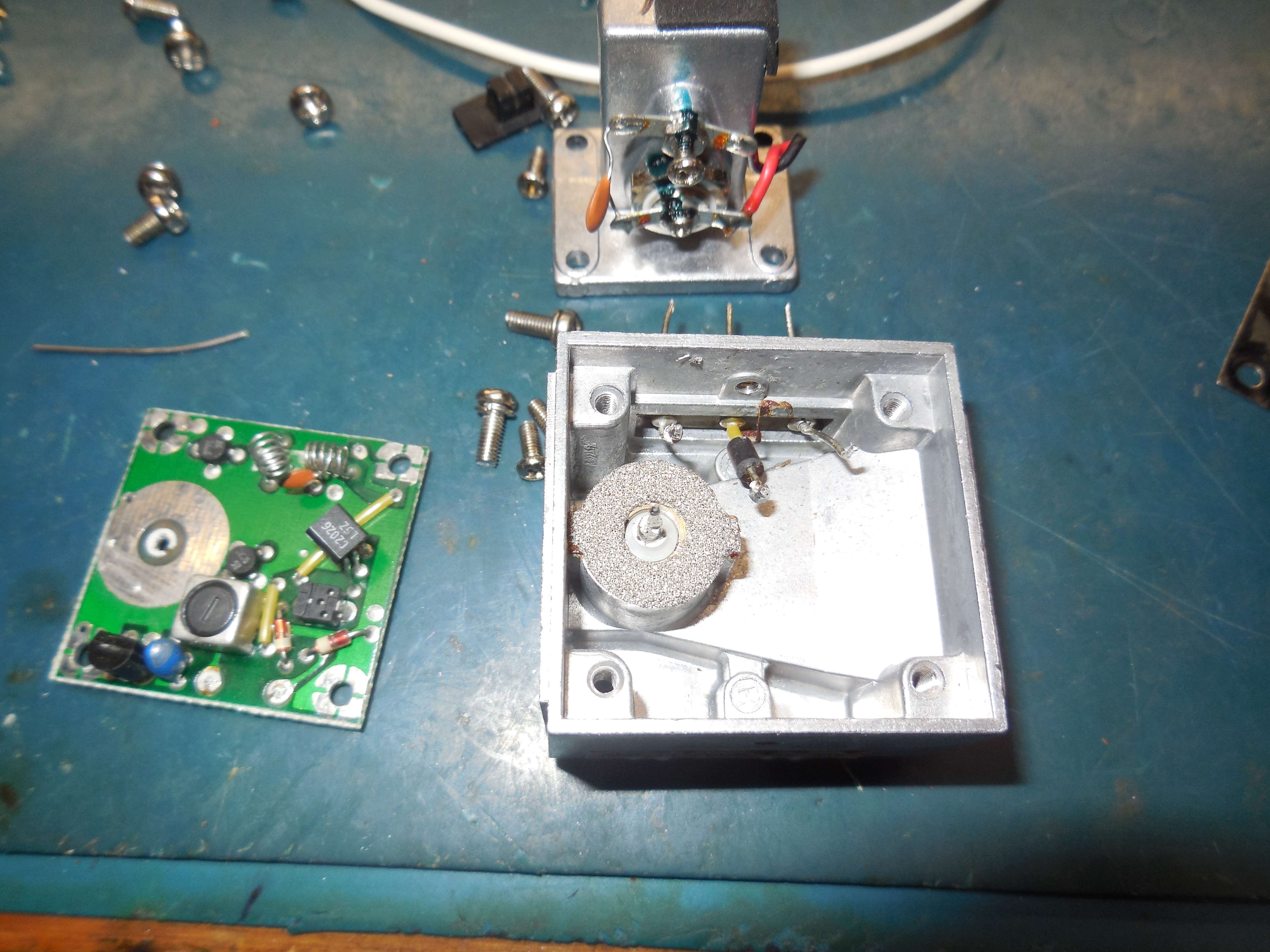
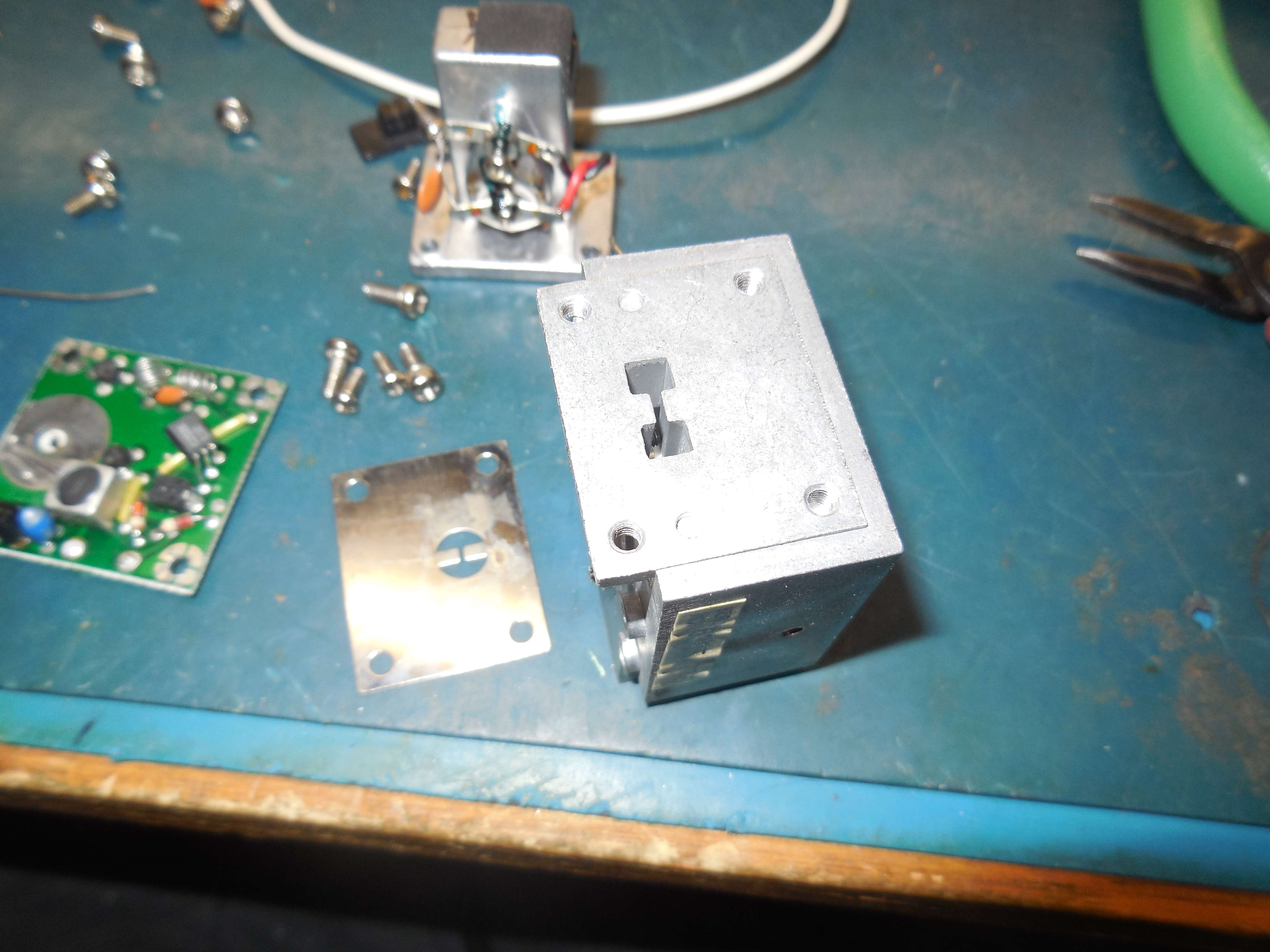
Example of the low-cost (but reliable) construction of an old Uniden X-band radar detector Gunn oscillator module.
The narrow section is the Gunn diode cavity for the 11.5 GHz local oscillator.
The 1N23 diode mixer mounted in front of it.
Commercial Ka-band Doppler speed radar modules.
Ka-band radar module with the horn antenna removed.
The mixer section is on the left, turnstile antenna (circular) post in the middle, and 36 GHz Gunn oscillator is on the right.
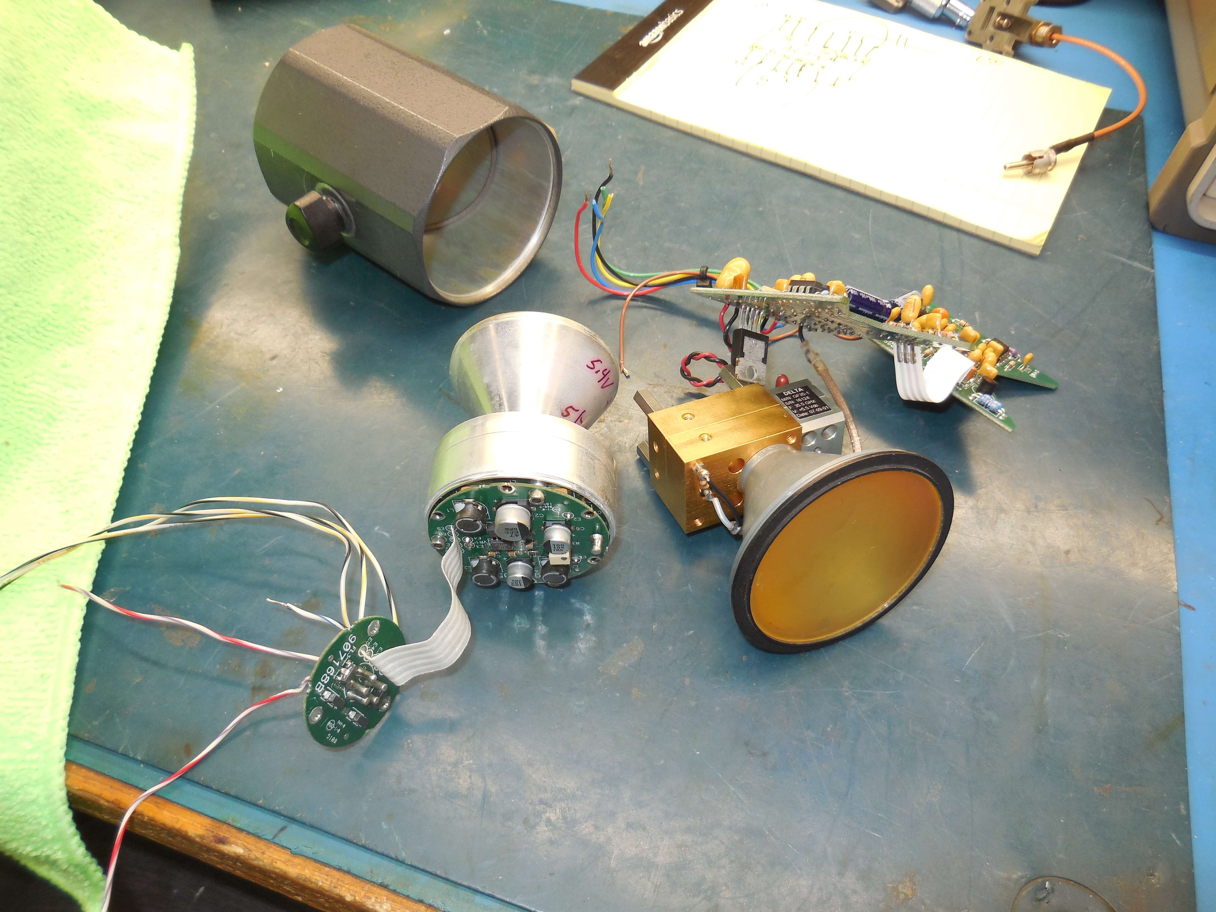
Cobra TRAPSHOOTER Pro II Radar Detector (Model RD-4100)
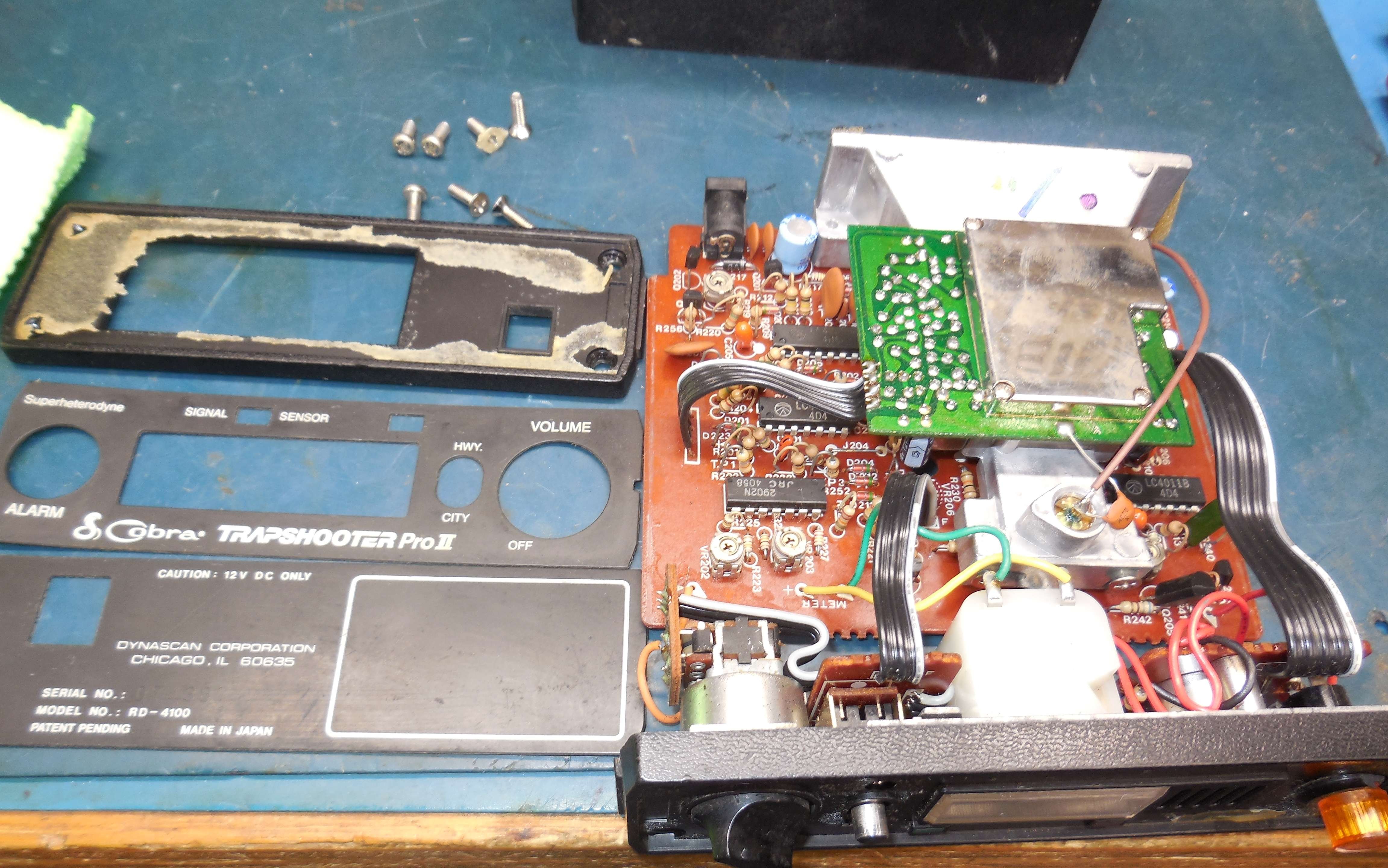
Internal view.
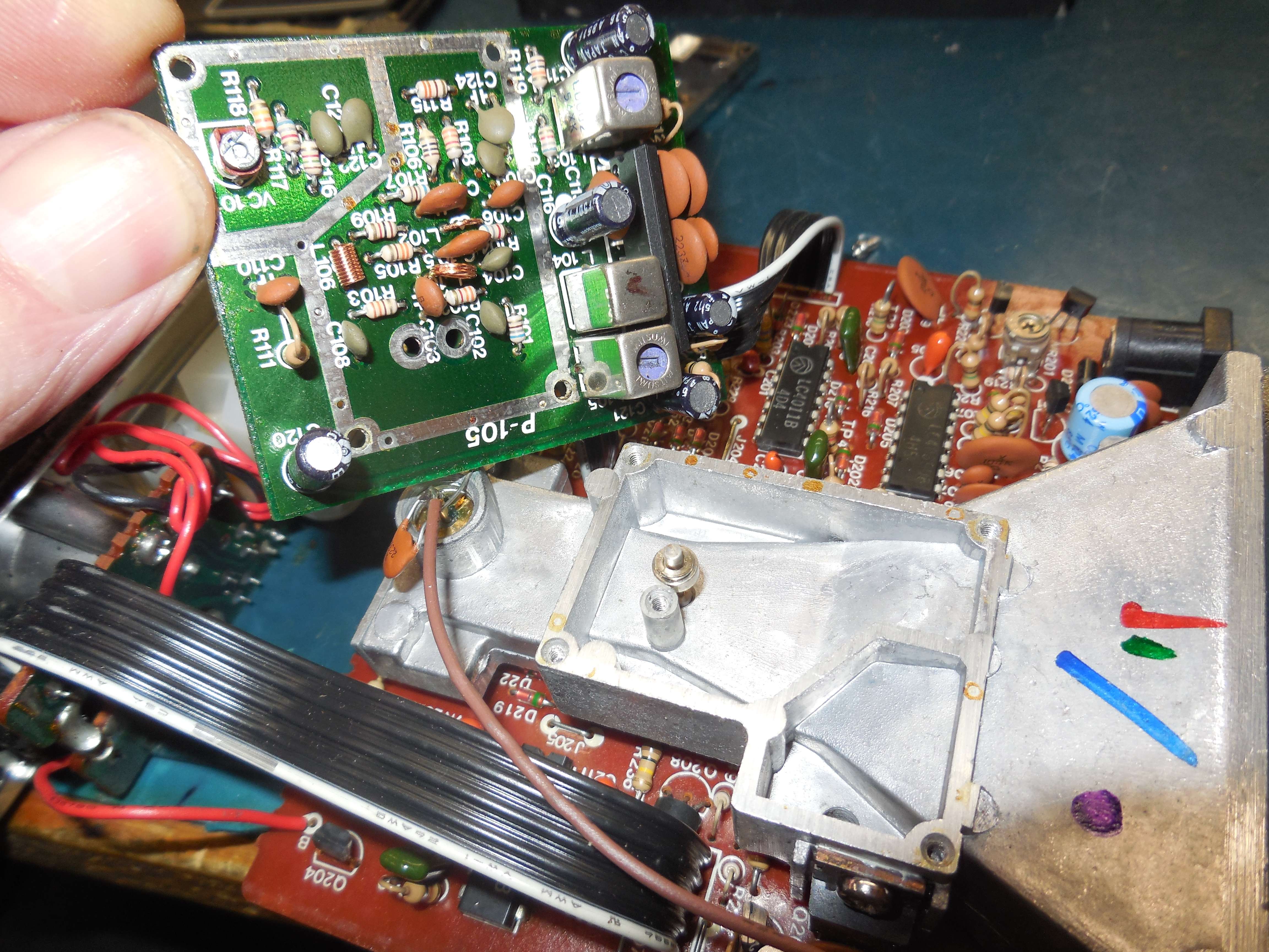
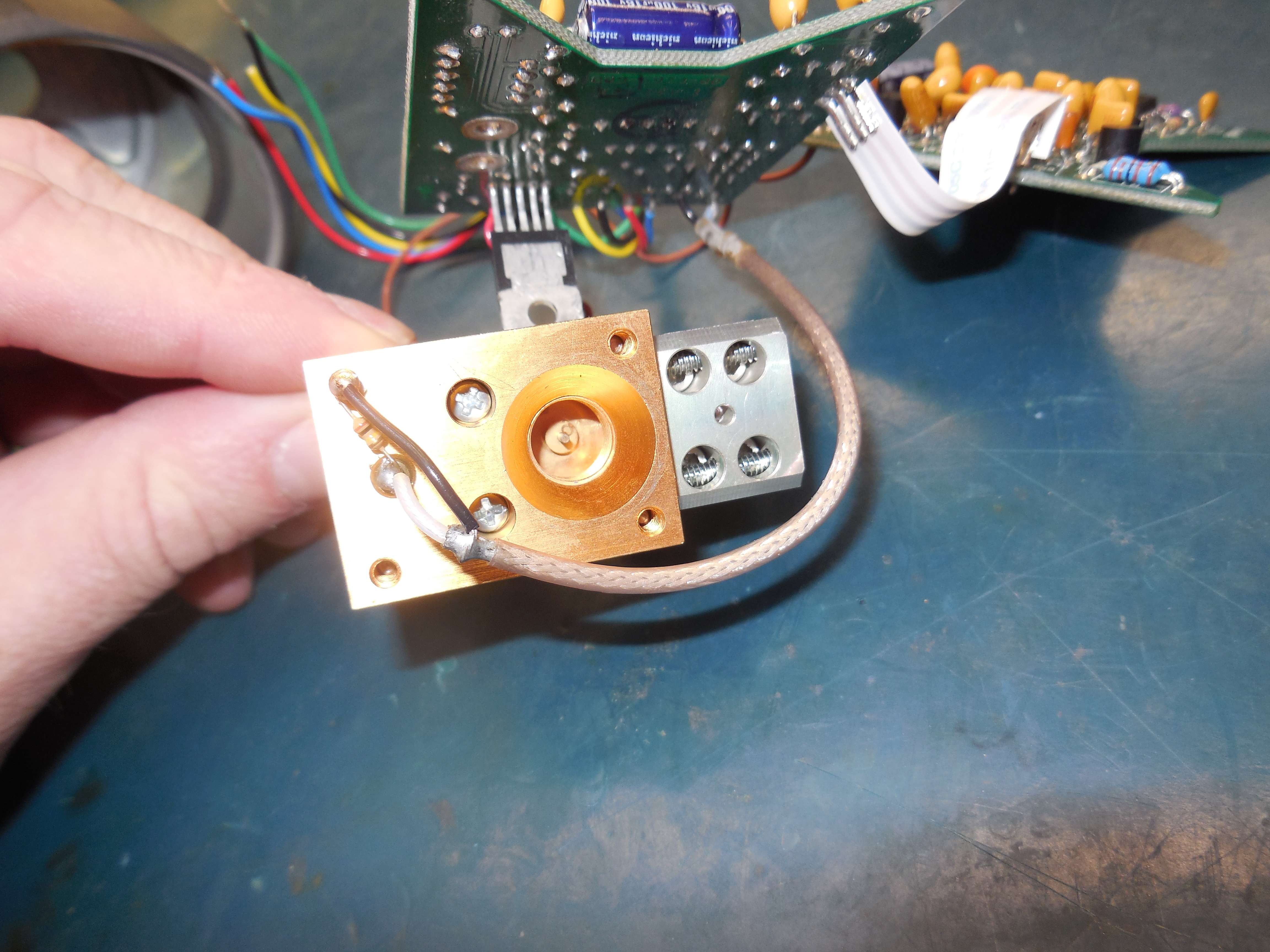
Overview of the mixer diode connection.
The local oscillator Gunn diode (+4.6 VDC) connection is on the rear of the horn antenna assembly.
The center post is the direct connection to the Schottky mixer diode. It's static sensitive, so be careful.
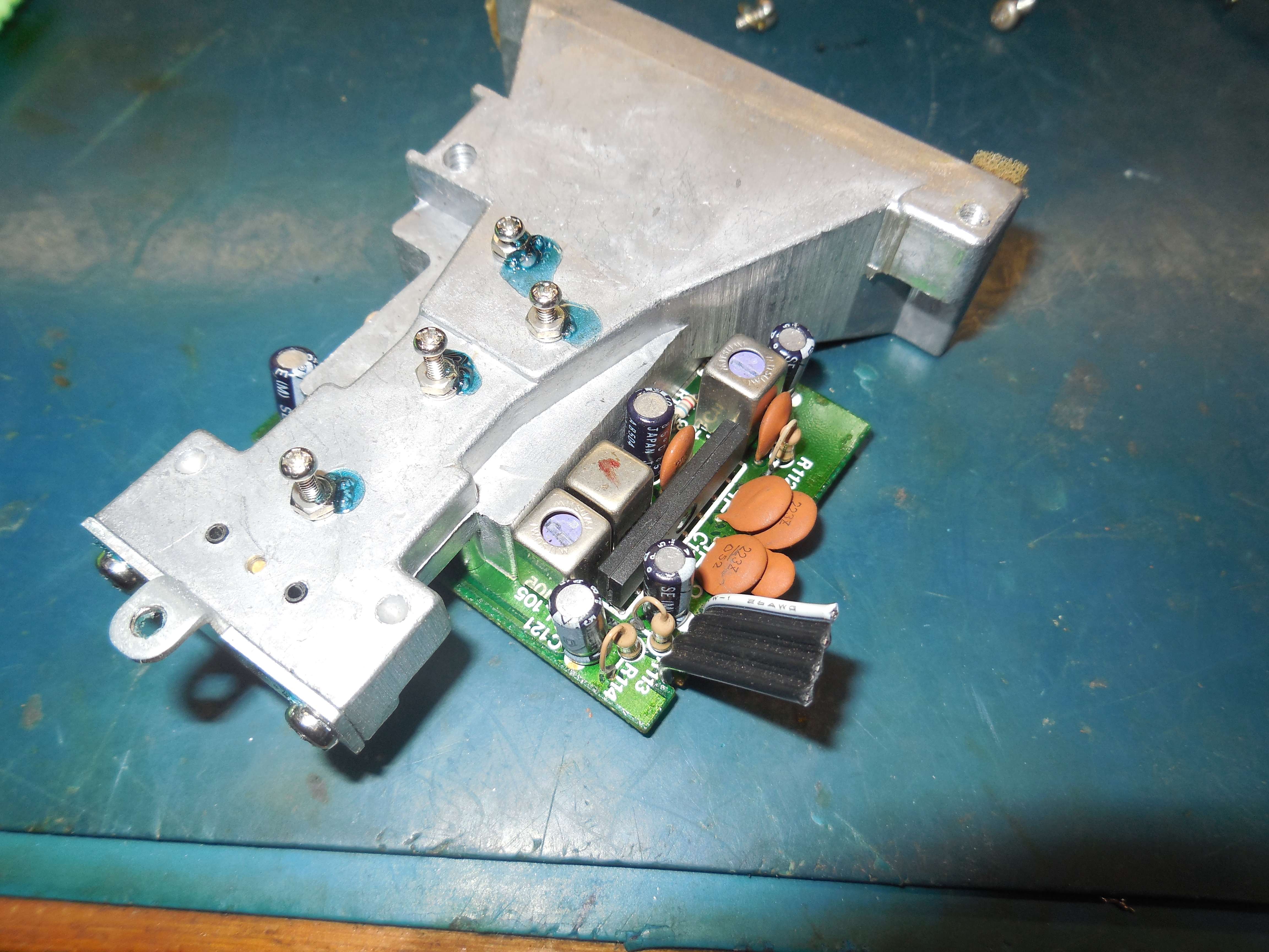
Bottom of the horn antenna assembly showing the tuning screws.
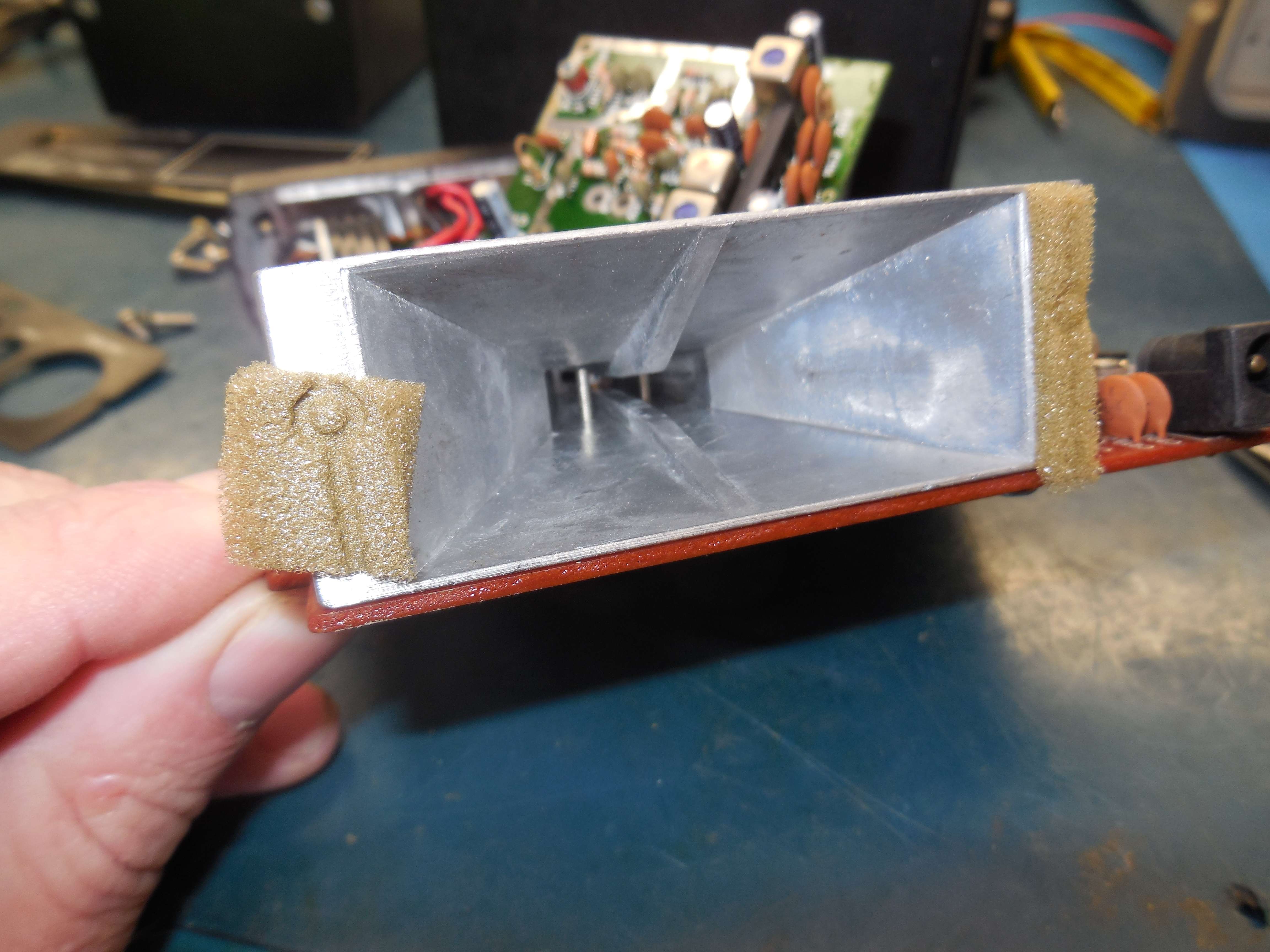
Looking down the horn antenna assembly showing the Schottky mixer diode.
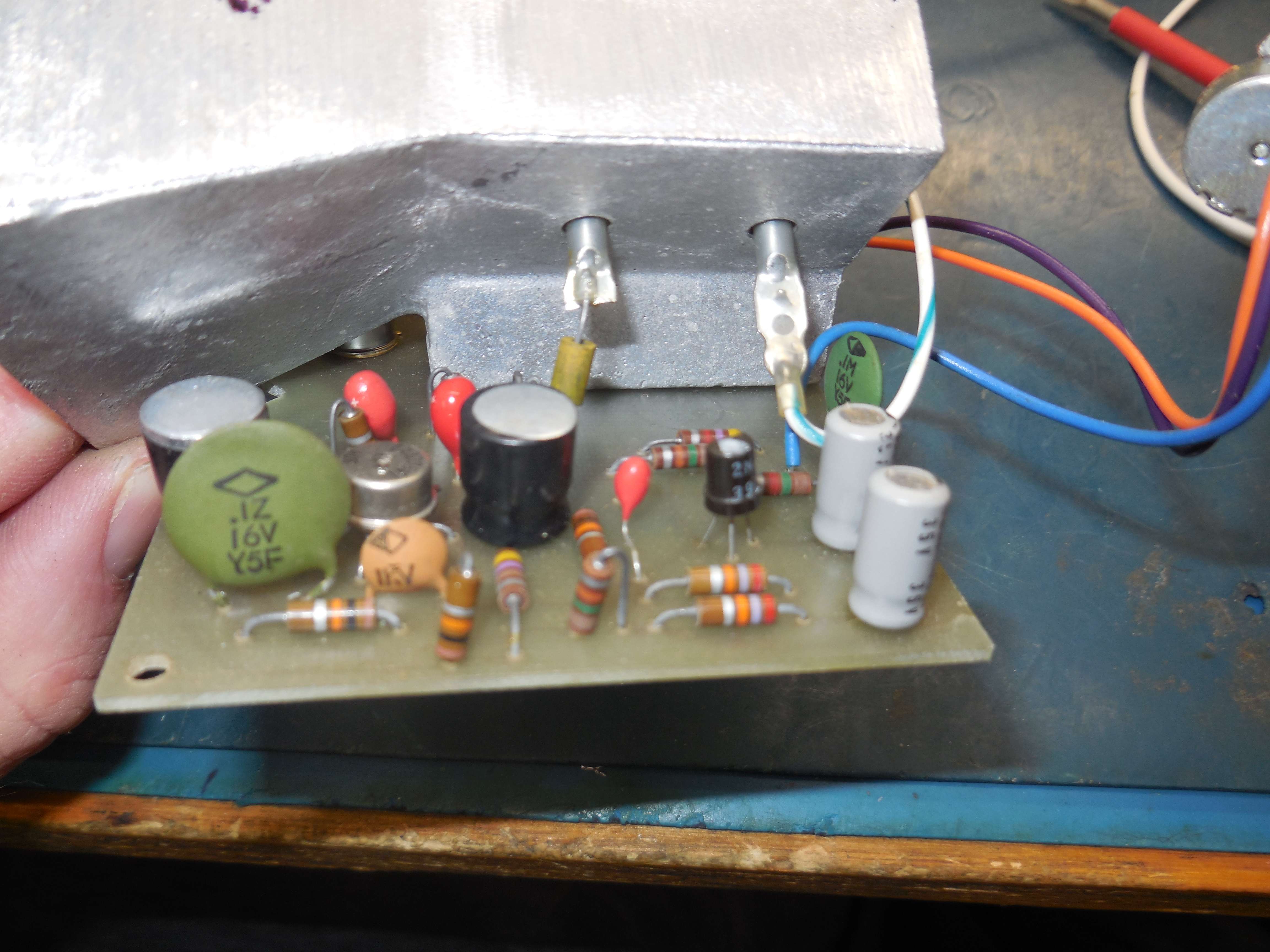
ELECTROLERT Fuzzbuster Radar Detector
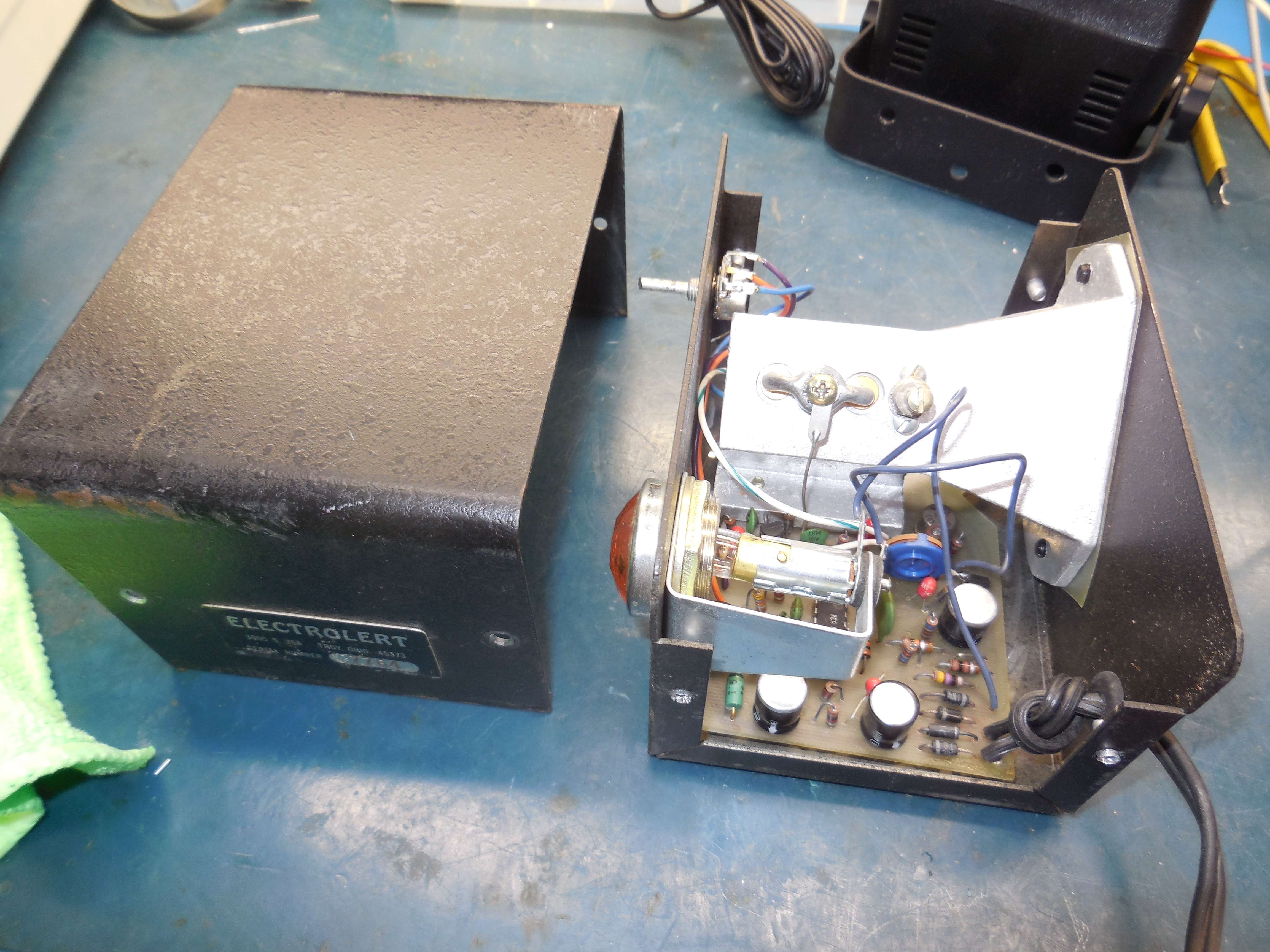
Internal view.
This is the infamous "Fuzzbuster." It's actually very well built (the designer, Dale T. Smith, was a research scientist at the Air Force Research Laboratory at Wright Patterson AFB). It's a parametric receiver, with just a 1N23CR diode feeding a CA3035 high-gain amplifier and another 1N23CR diode feed with a 600 Hz 5 Vp-p square wave signal.
It only covers the X-band (10 GHz) and uses 1N23CR point-contact diodes. It has a beautiful die-cast horn antenna which can be used for other 10 GHz projects.
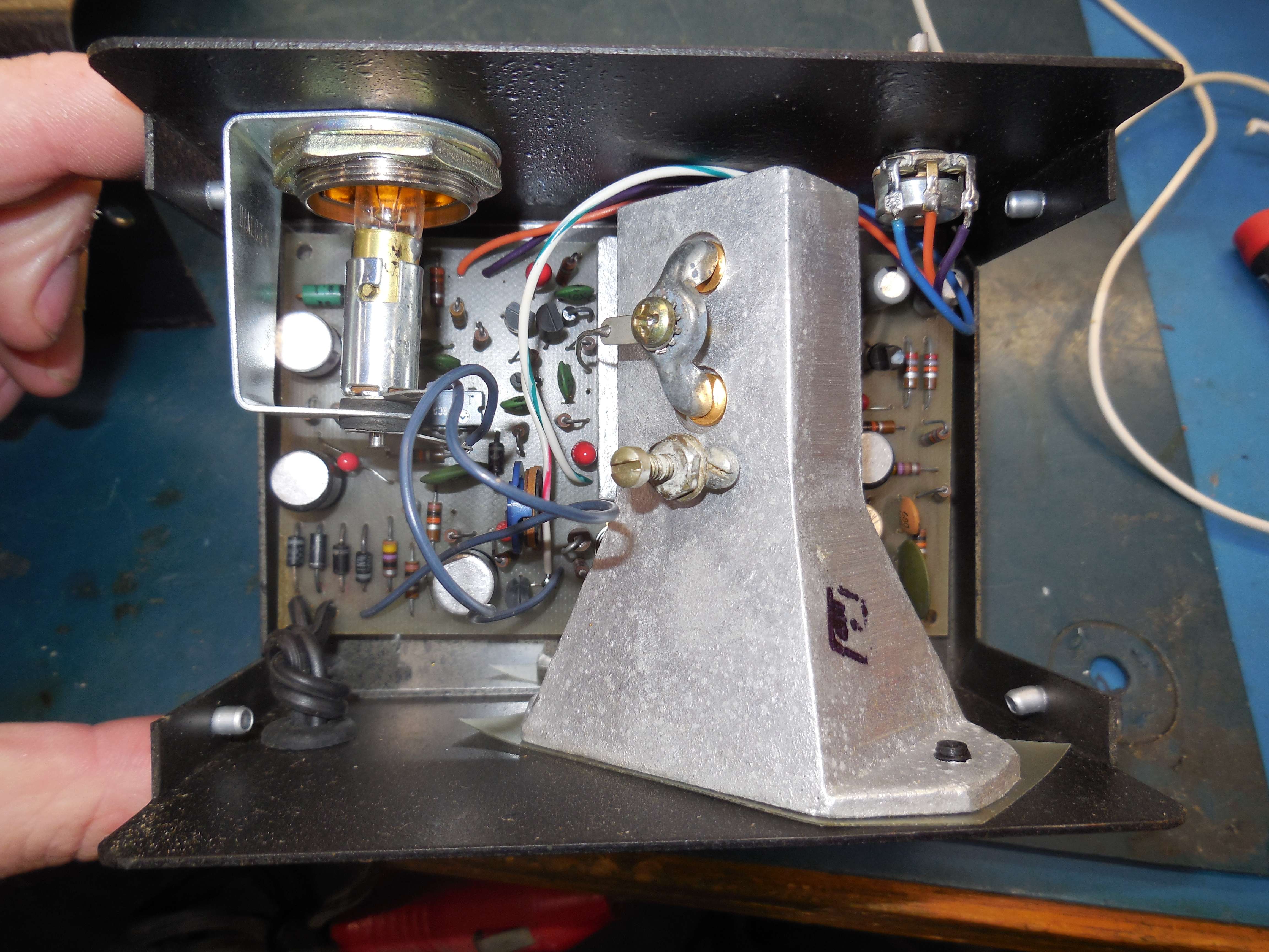
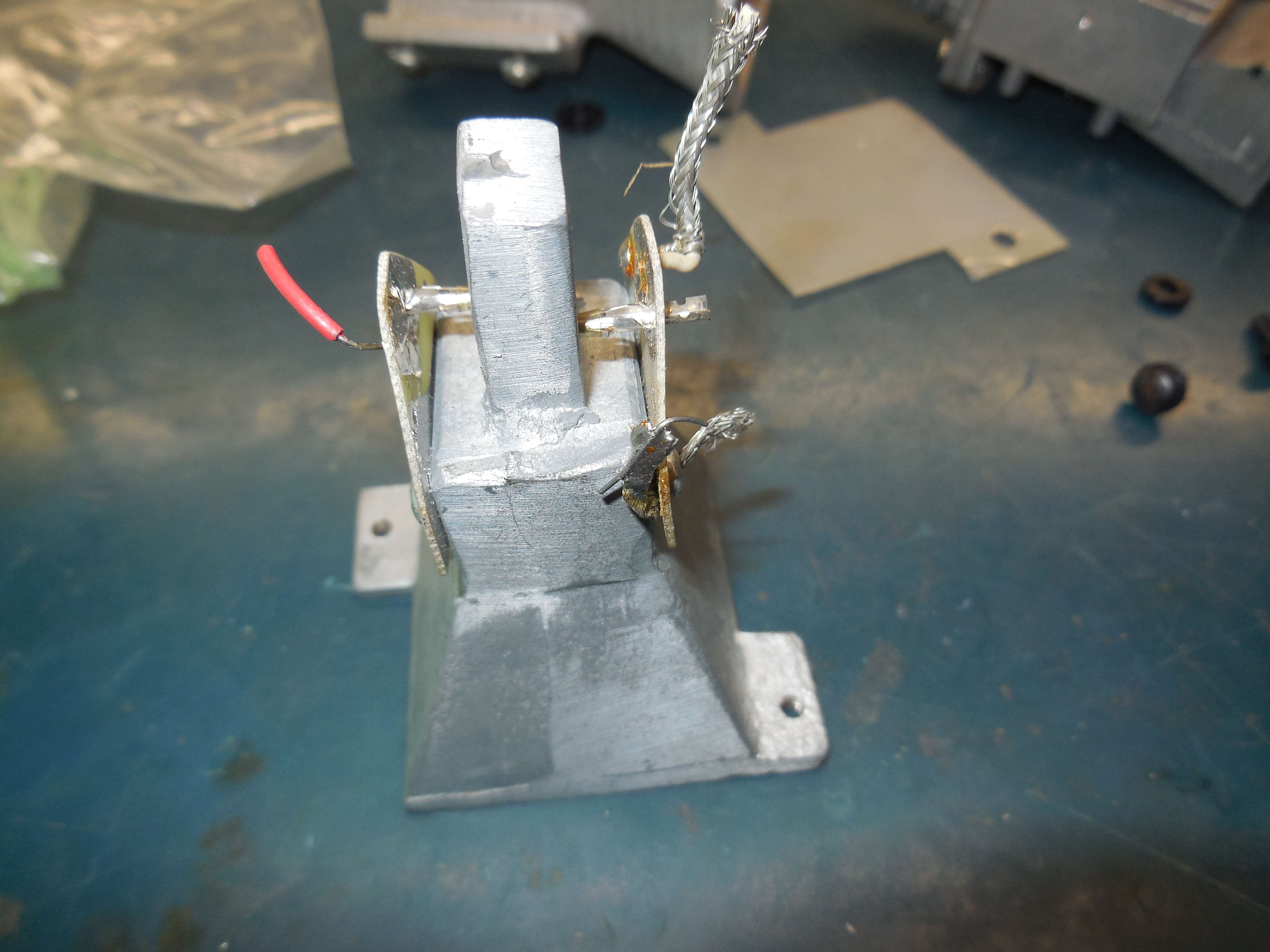
Alternate view.
The weird prong connector is the ground connection for the 1N23CR diodes.
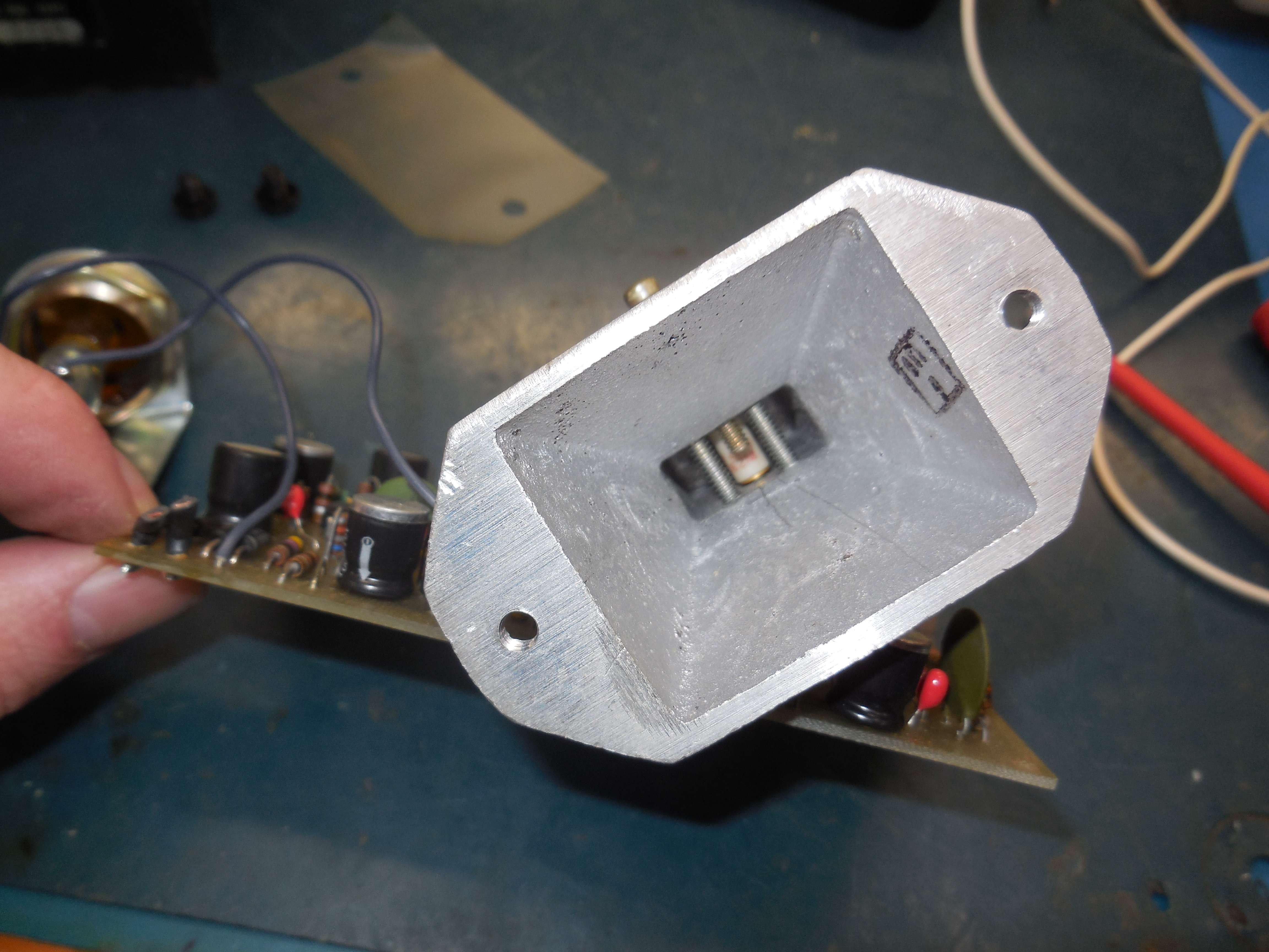
Looking down the horn antenna assembly showing the 1N23CR mixer diodes.
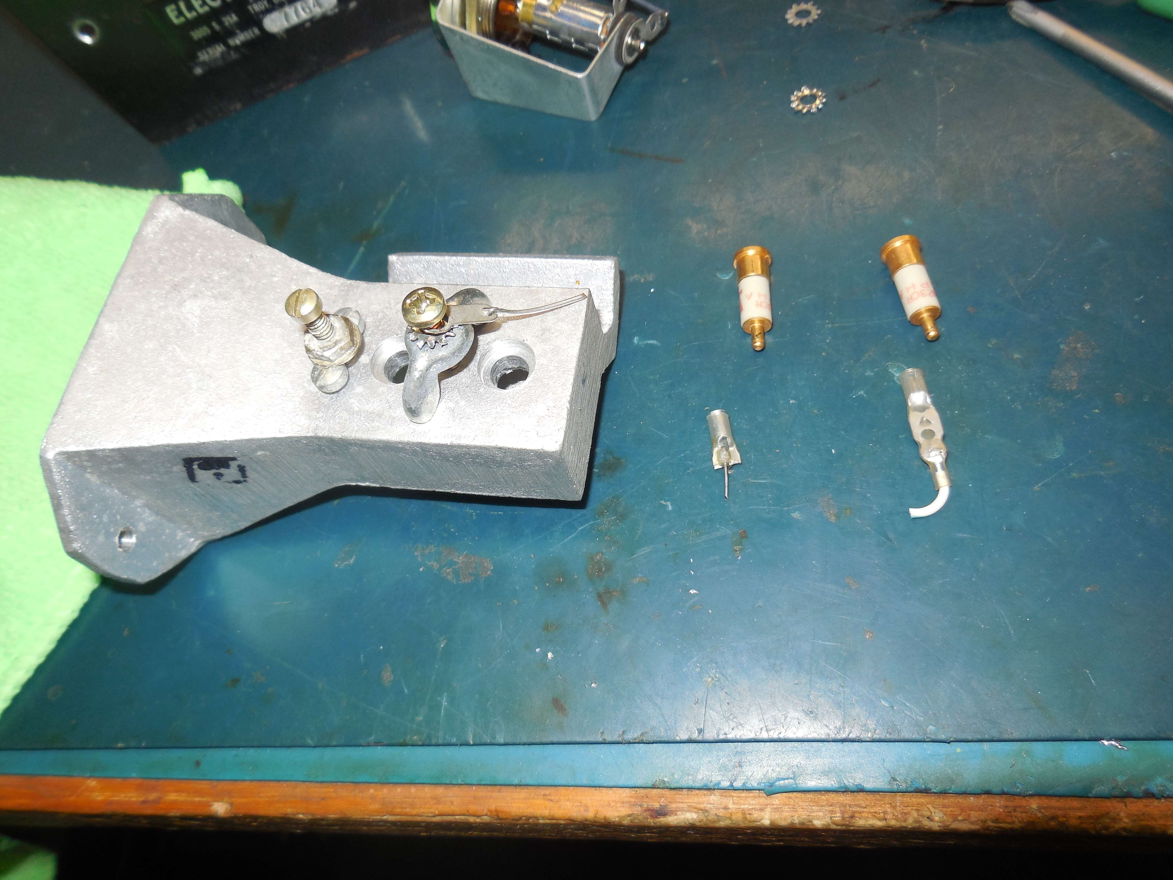
Overview of the 1N23CR point-contact diodes.
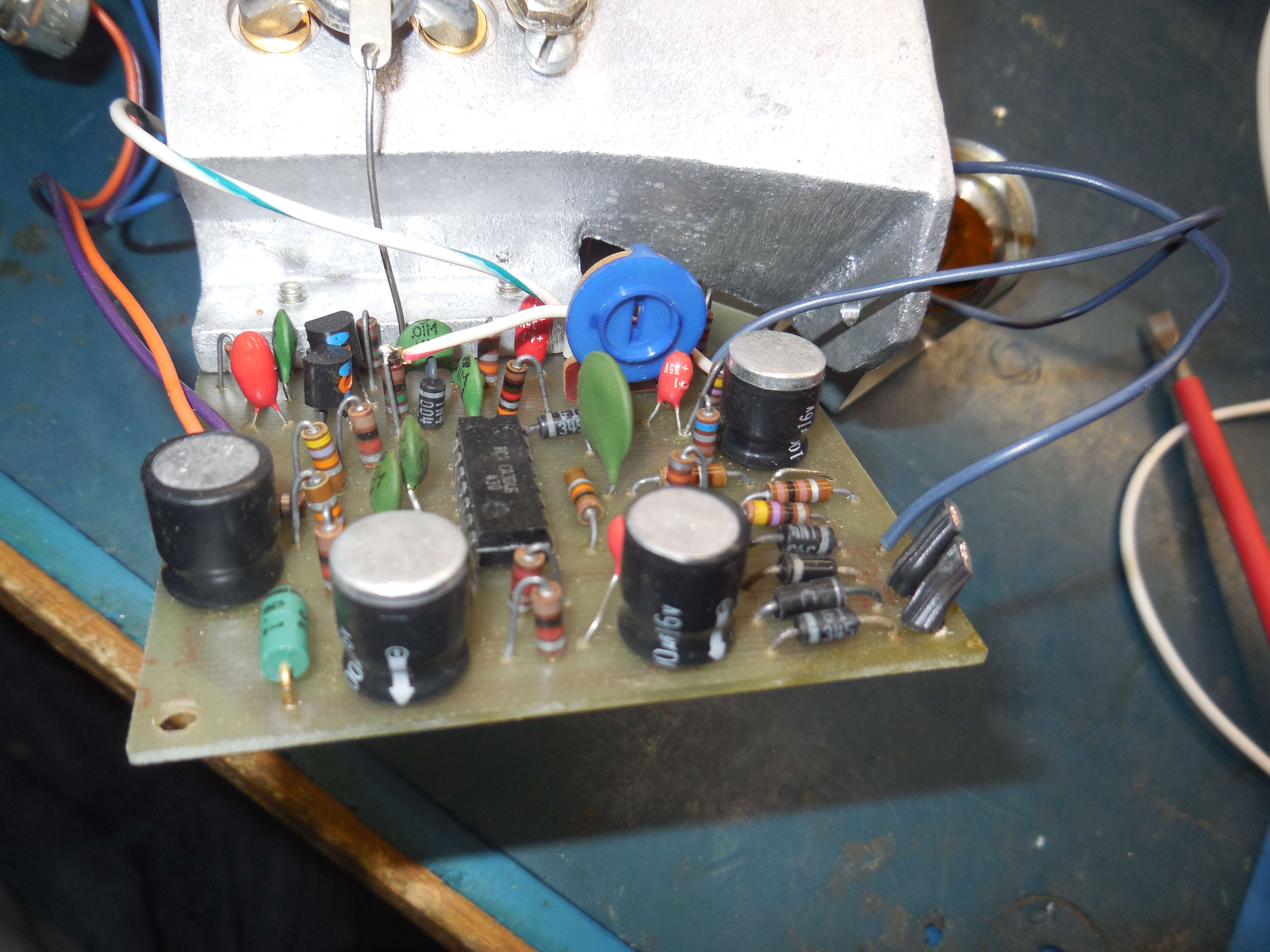
PC board, side view.
The connection on the left is for the main RF detection 1N23CR mixer diode. It feeds a CA3035 high-gain post-mixer amplifier.
The rear 1N23CR diode is modulated with a 600 Hz tone.
PC board, other side view.
This contains the DC power supply filtering and the 600 Hz oscillator.
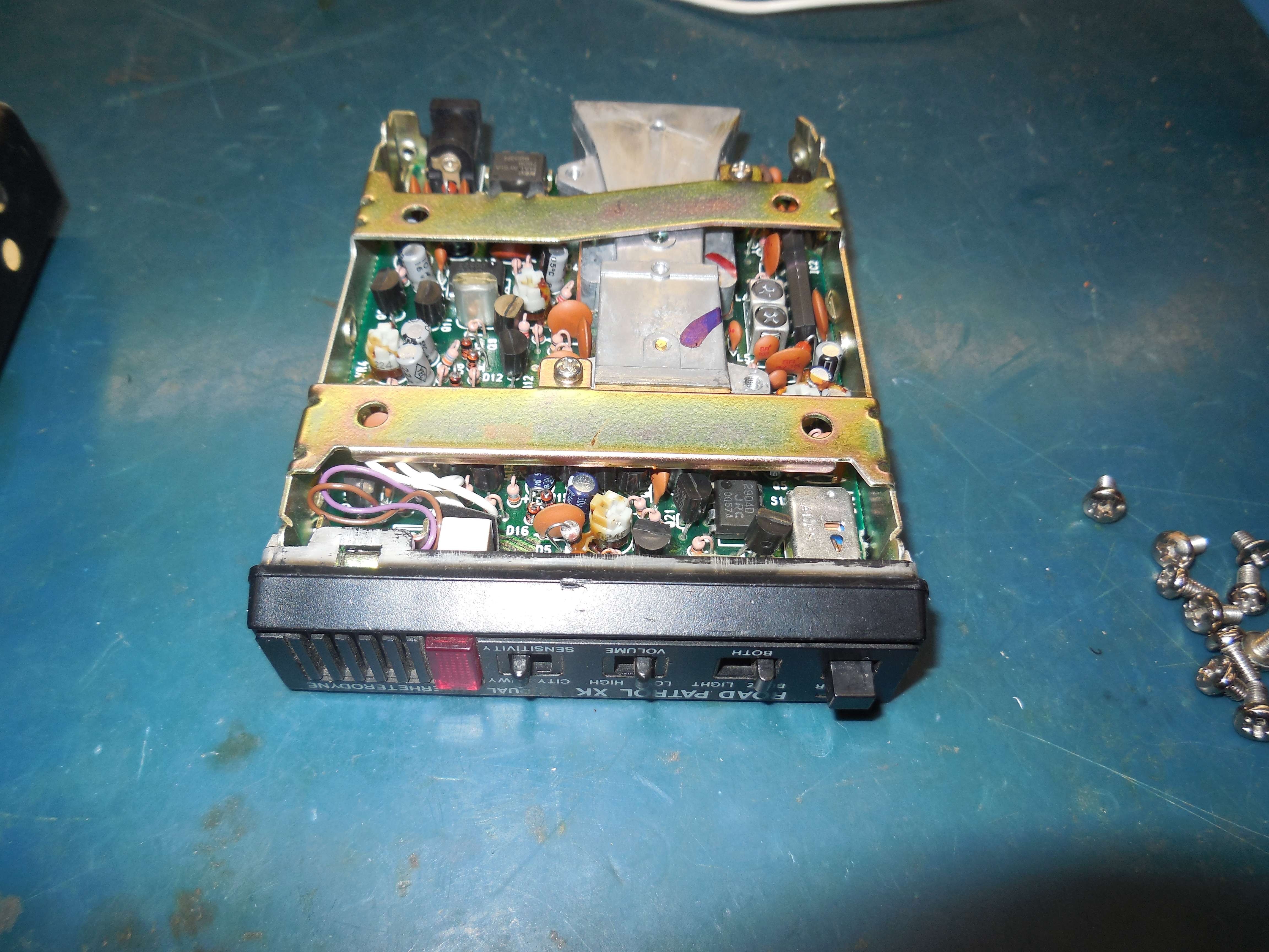
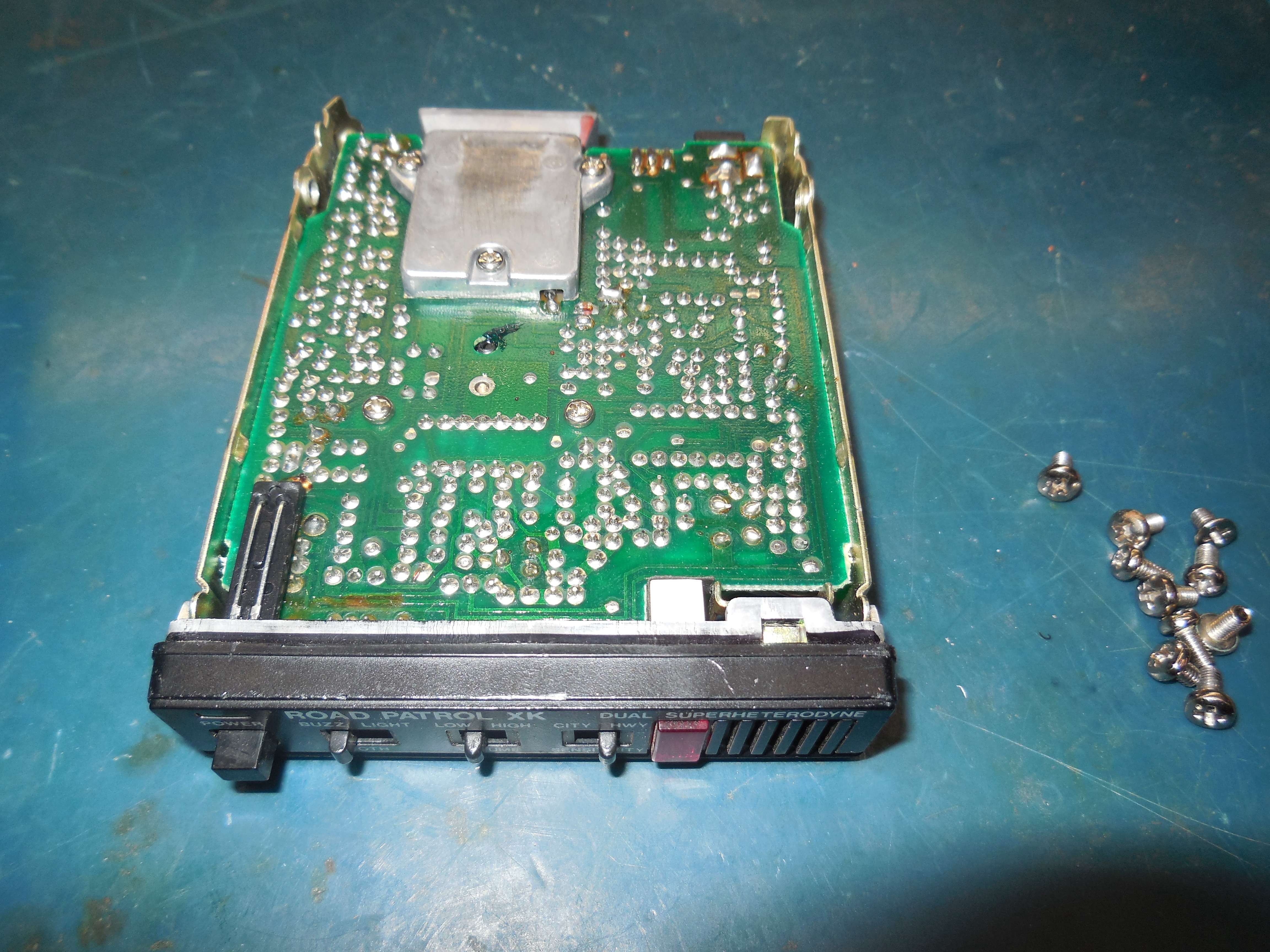
MICRONTA Road Patrol XK (RadioShack Part No. 22-1612)
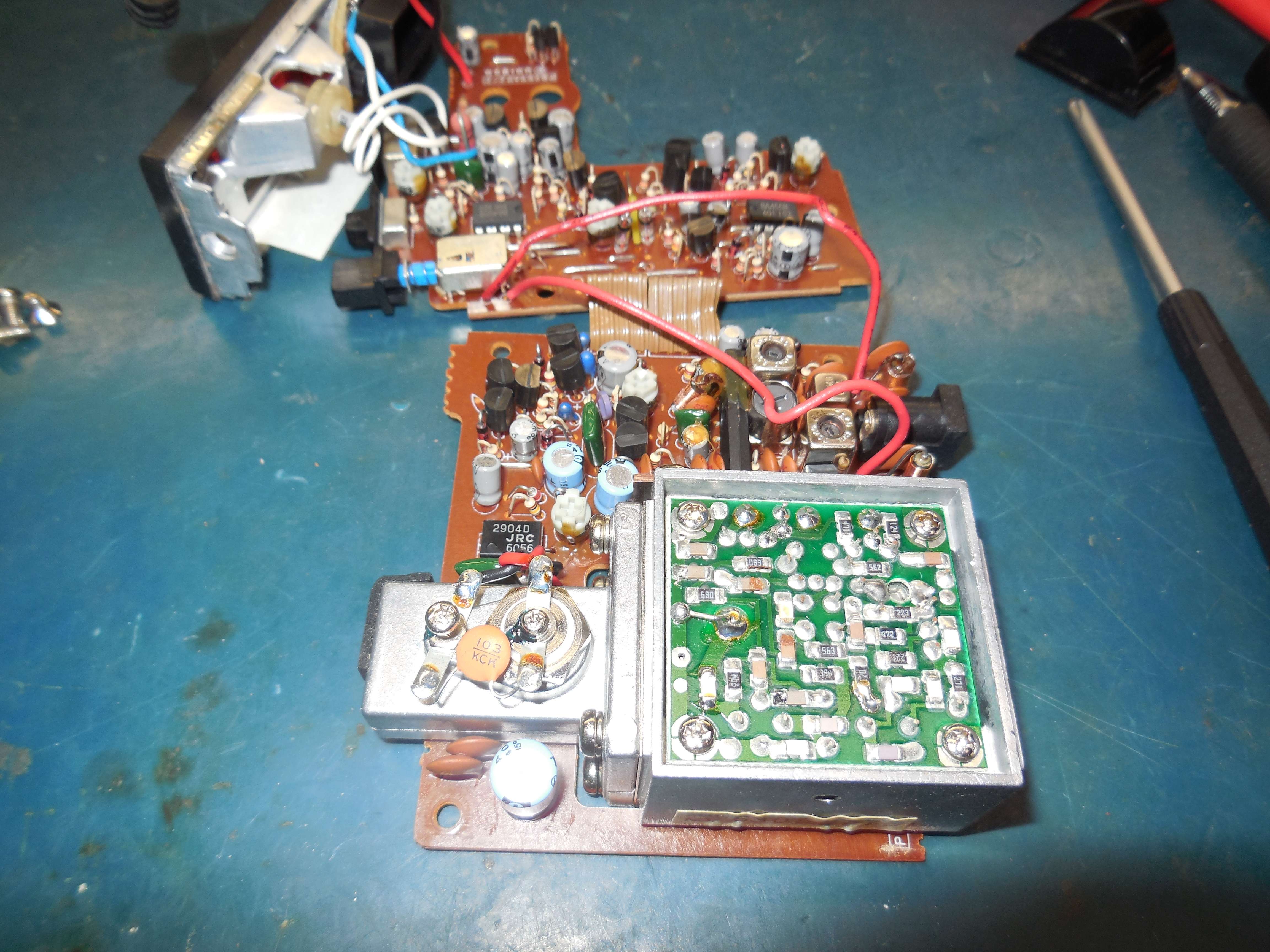
Internal view.
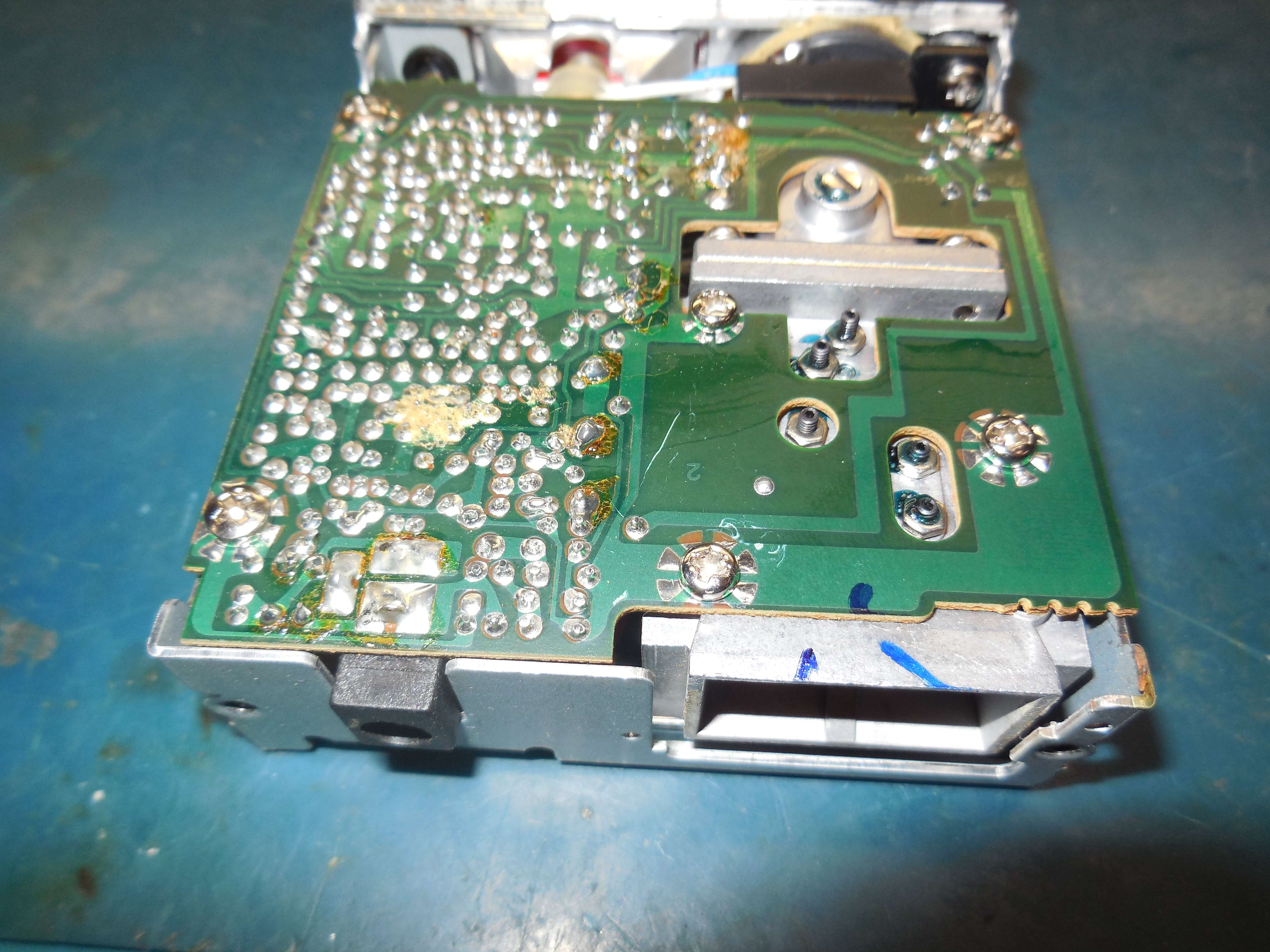
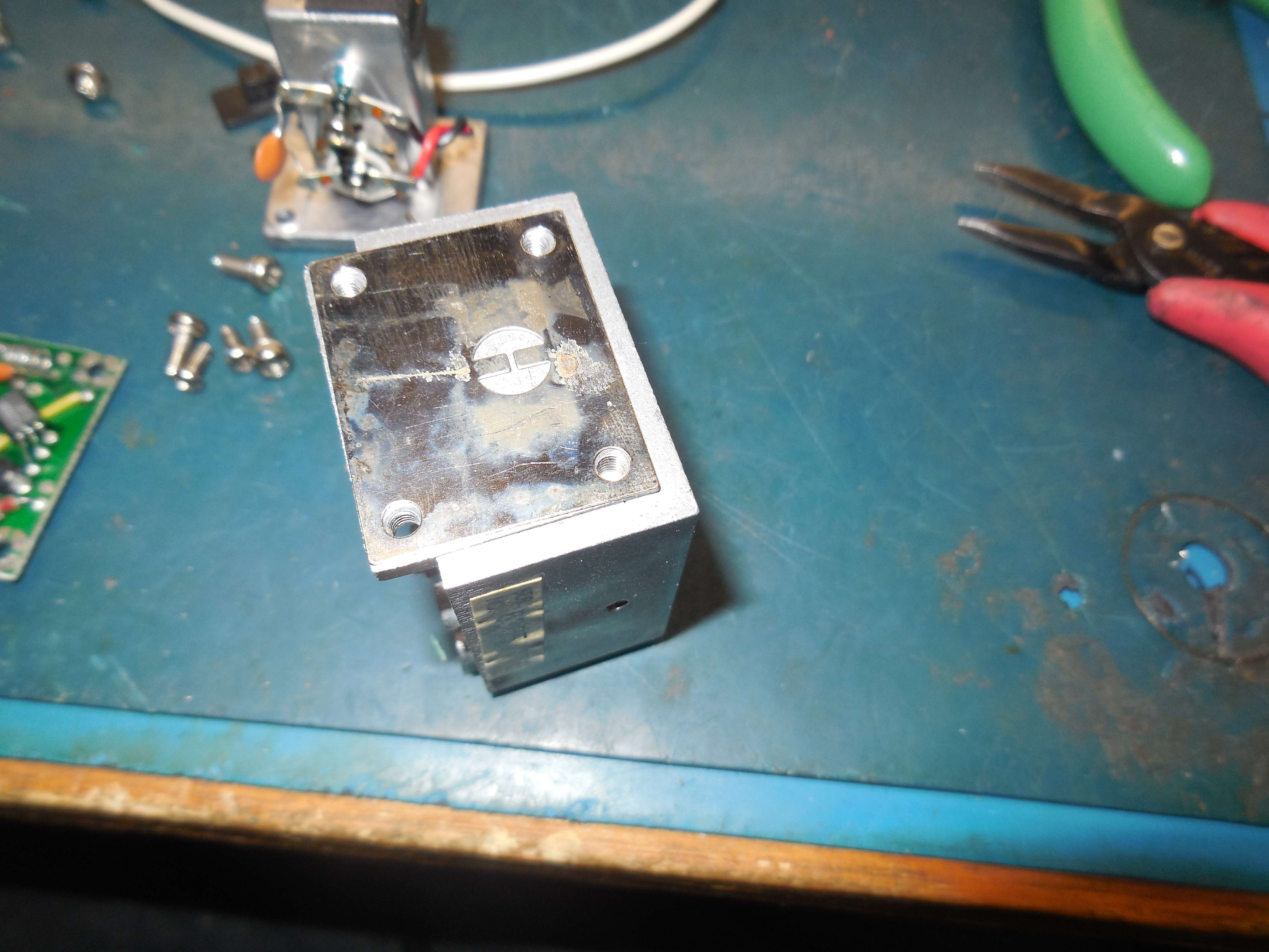
Bottom view.
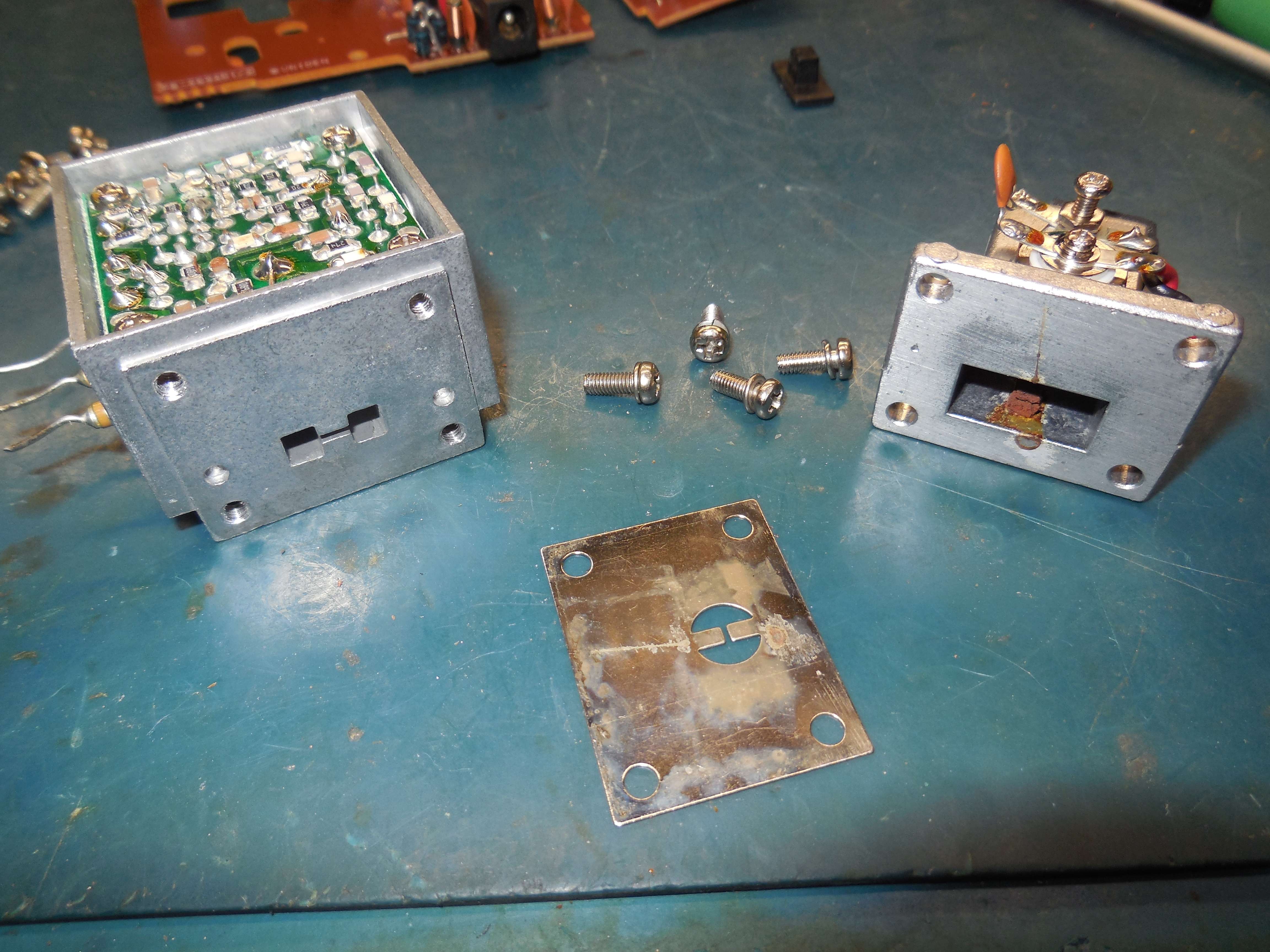
Mixer section on the left, iris plate in the middle, Gunn diode oscillator section on the right.
These are the best, as you can remove the Gunn local oscillator from the horn assembly and just use the mixer section.
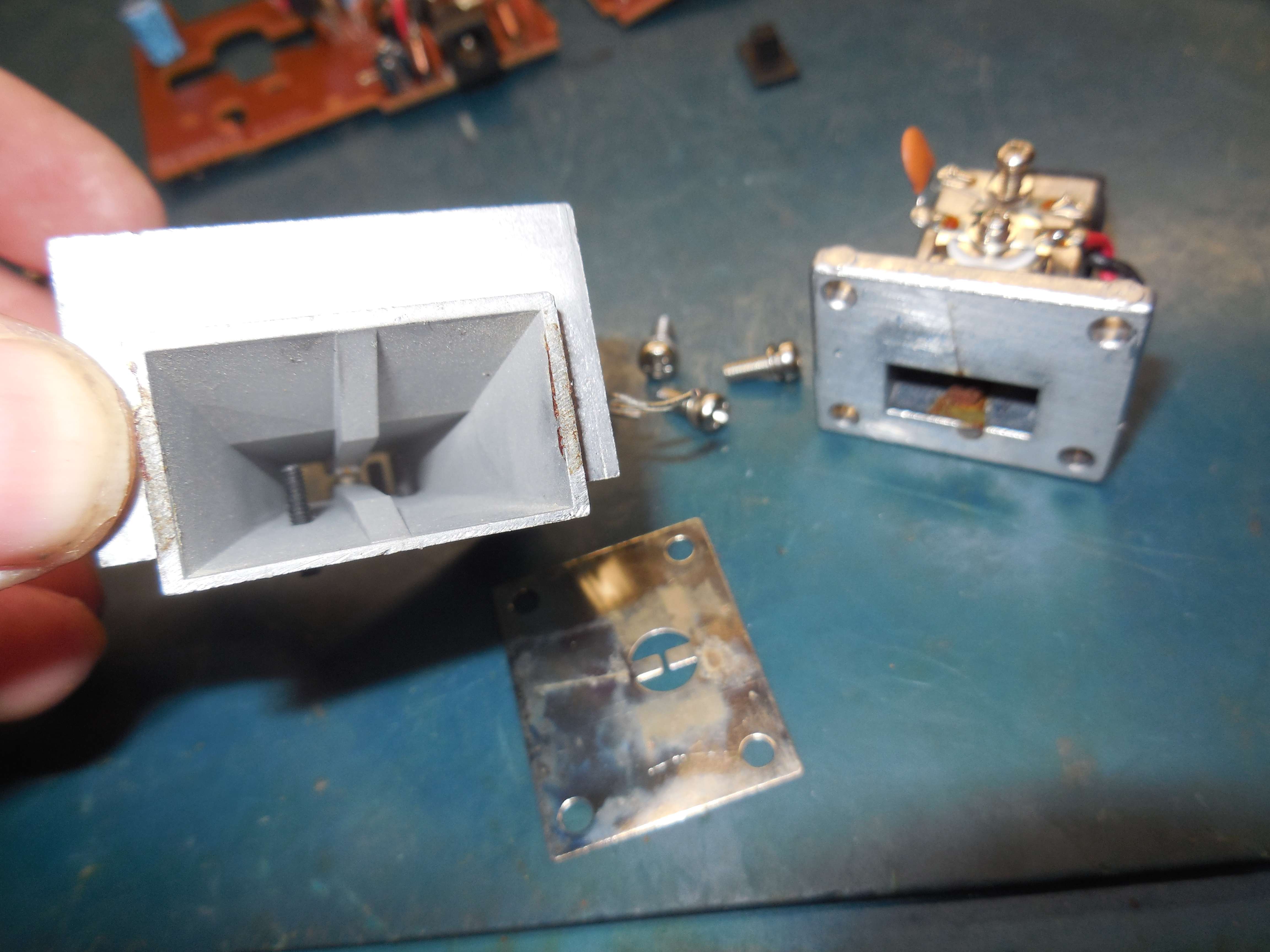
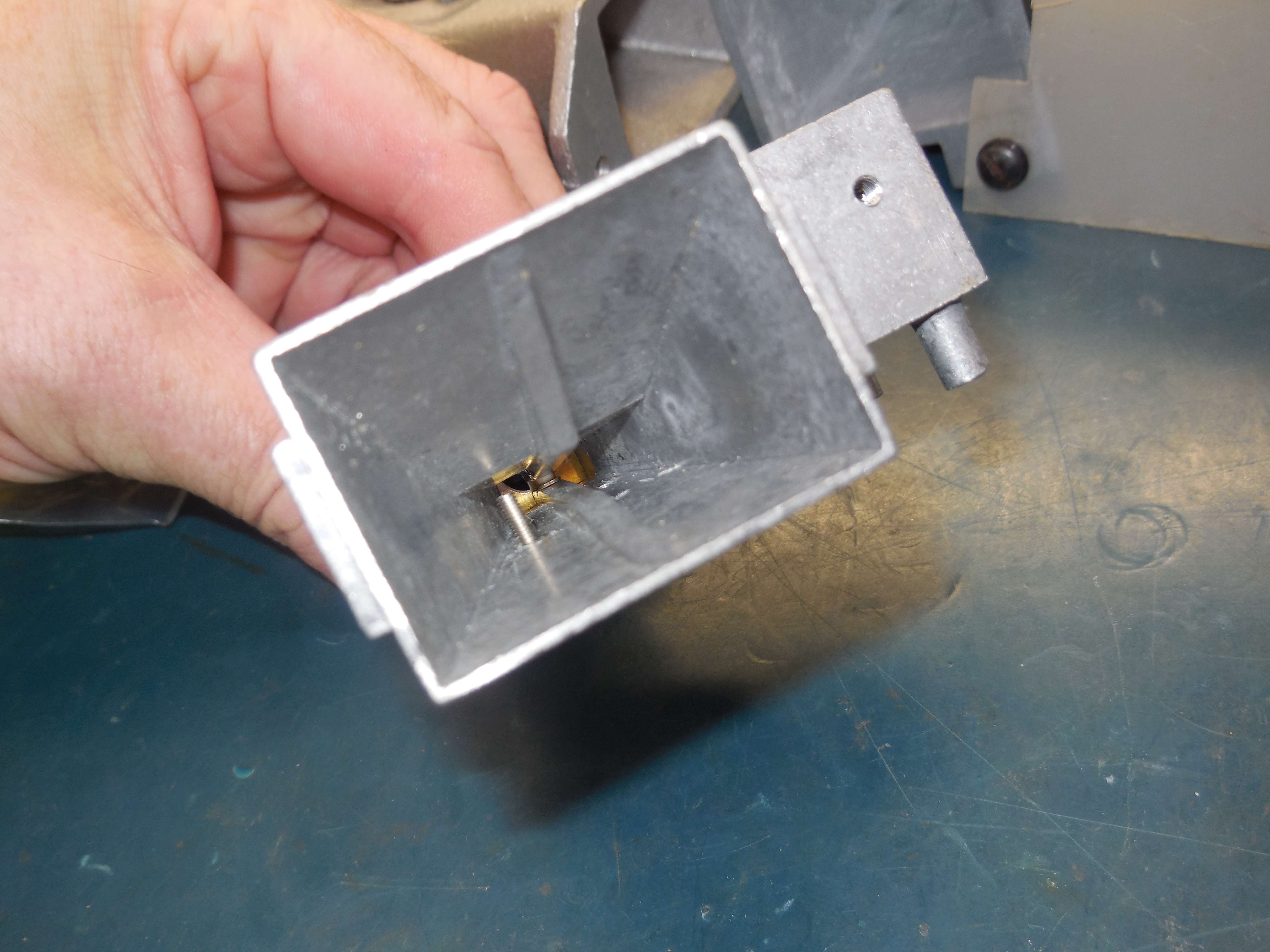
Look down the horn antenna.
Internal view of the mixer section of the horn antenna assembly.
Rear view of the horn antenna assembly.
This will need to be sealed off.
You can flip the Gunn diode iris plate around to seal off the rear end of the mixer section of the horn antenna assembly.
MICRONTA Road Patrol XK (RadioShack Part No. 22-1619)
Overview.
It's much smaller than the previous RadioShack Part No. 22-1612 model.
Alternate view.
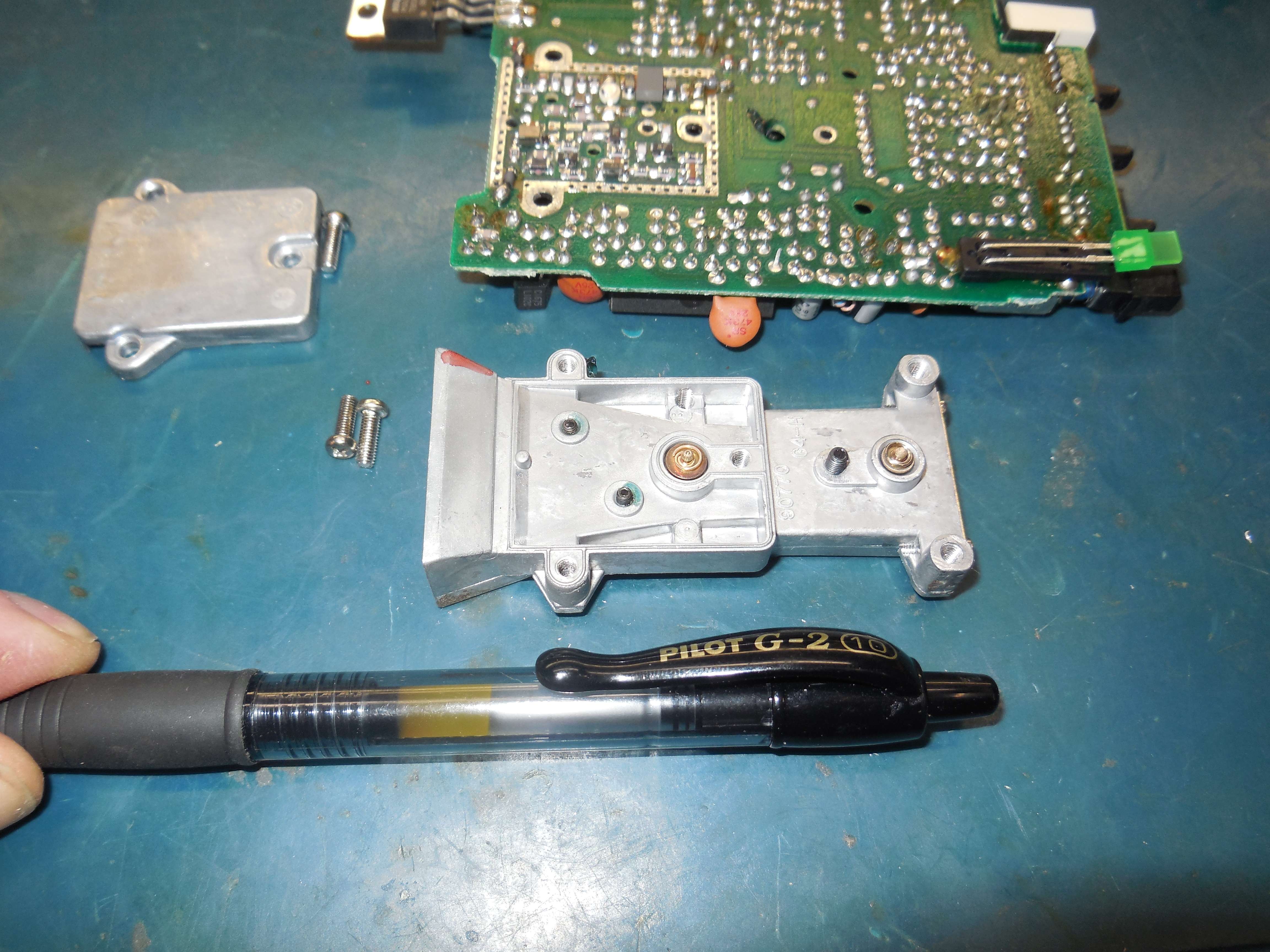
Horn assembly next to a Pilot G2 pen.
Mixer diode is on the left, local oscillator Gunn diode is on the right.
You'll need to make a little PC board to "push" down on the mixer diode holding spring.