Using the MicrowaveSolutions Ltd MDU 1000 Series Motion Detector Unit
1. Introduction
The Microwave Solutions Ltd MDU (Motion Detector Unit) is aminiature microwave doppler radar sensor optimised for low powerconsumption, short range (<30 metres) and low cost.
Variants as listed in the Table 1 are currently available.
Table1
Model | Construction | Nominal Frequency | Primary Application |
| MDU1000 | Metal | 10.587GHz, 10.687GHz | UK |
| MDU1000 | Metal | 10.525GHz | Holland, Belgium, USA outdoor |
| MDU1020 | Metal | 10.525GHz | USA indoor |
| MDU1020 | Plastic | 10.525GHz | USA indoor |
| MDU1030 | Metal | 9.90GHz | France, Italy, Switzerland |
| MDU1100 | Plastic | 10.587GHz, 10.687GHz | UK |
| MDU1120 | Plastic | 10.525GHz | Holland, Belgium, USA outdoor |
| MDU1130 | Plastic | 9.90GHz | France, Italy, Switzerland |
The MDU1000 and MDU1100 variants are Type Approved to MPT1349(Type Approval Number 4379). The MDU1020 variants are designed tocomply with FCC Part 15 Regulations. The MDU1030 variant isdesigned to comply with CNET specification ST/EST/EFT/217 FrenchPTT). The MDU1120 and MDU1130 variants are designed to complywith specification ETS 300-440.
The MDU emits a low level X Band microwave signal which isreflected from all objects within its coverage area. If any ofthe objects that the signal has bounced off are moving towards oraway from the sensor the frequency of the reflected signalreceived back by the sensor will be increased or decreased fromthe frequency of the transmitted signal by the Doppler effect.
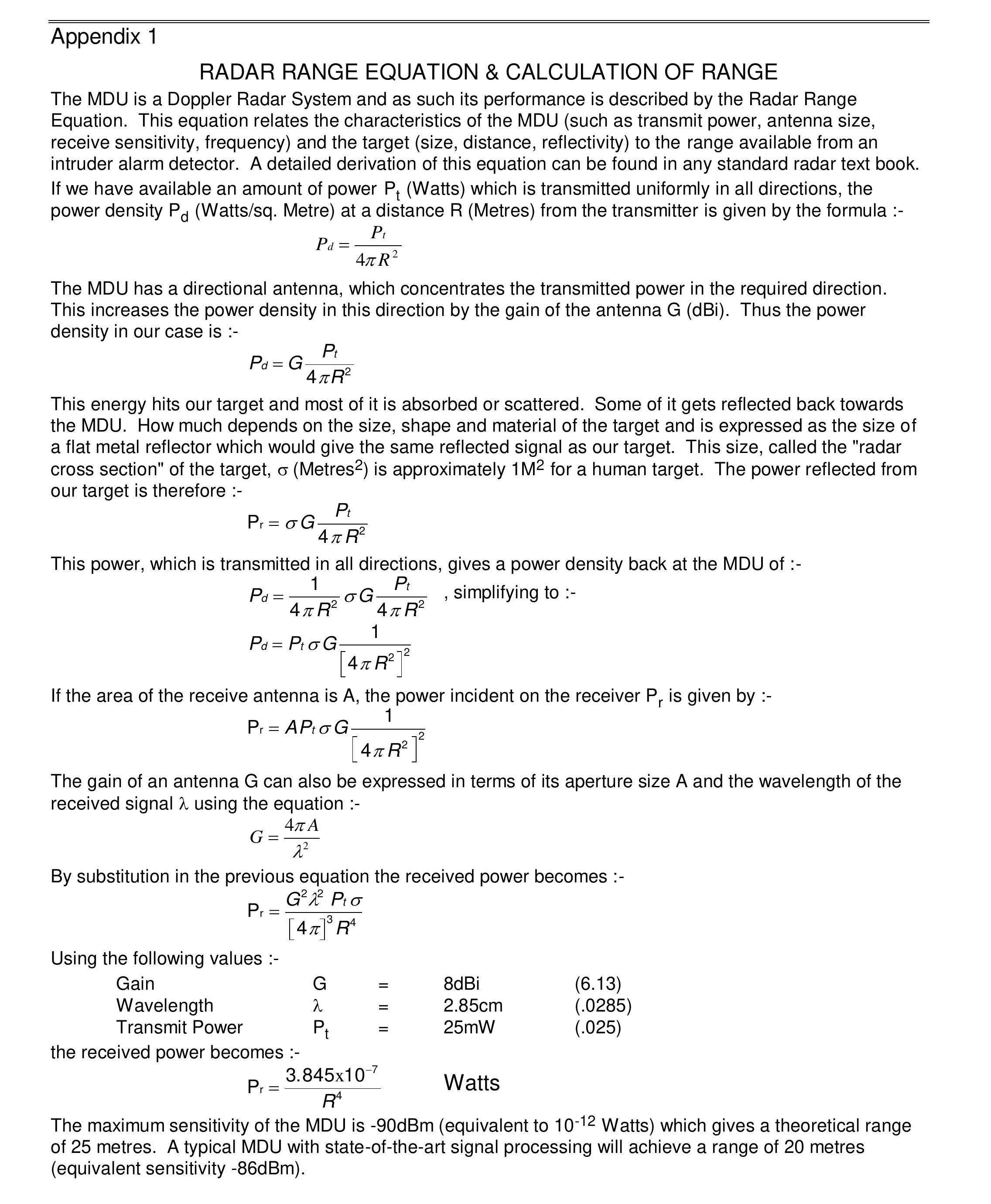
The MDU compares the transmitted and received frequencies andproduces an output signal, the frequency of which is proportionalto the velocity of the object. The amplitude of this signal is acomplex function of the size and reflectivity of the object andits distance from the MDU, as well as the characteristics of theMDU. A discussion of range is contained in Appendix 1 "RadarRange Equation".
Signal processing circuitry (not provided with the unit)amplifies this signal and analyses its frequency spectrum. If thesignal strength is above a threshold level, and has the requiredfrequency spectrum an output signal can be generated.
In order to conserve power it is usual for the MDU to bepulsed on and off rapidly so that it is only transmitting forapproximately 5% of the time. As well as reducing powerconsumption, this also reduces the average power transmitted.
This does not reduce the ability of the MDU to detect movingobjects.
2. Circuit Description
The Microwave Solutions Ltd Motion Detector Unit contains adielectric resonator stabilised microwave FET oscillator,providing a frequency and amplitude stable signal at theoperating frequency of the unit. The power from this oscillatoris filtered to remove harmonic and spurious signals and is thensplit into two approximately equal amplitude signals.
One of these signals is further filtered and feeds thetransmit antennas of the unit, illuminating the volume to beprotected. The other signal is routed to the local oscillatorinput of a balanced mixer providing the reference signal againstwhich the Doppler return signal is compared.
The Doppler return signal, reflected from the target iscollected by the receive antennas and coupled to the RF input ofthe balanced mixer, where it is compared with the transmittedsignal. The Doppler frequency is extracted and is available atthe IF output of the unit for signal processing.
3. Oscillator
The oscillator requires 5V ± 0.25V applied to the +5Vterminal of the device. If the oscillator is powered continuously(CW mode) the current consumption is typically 50mA. For lowpower consumption it is usual to operate the unit in pulsedmode,supplying the oscillator with 5V pulses with a typical pulsewidth of 30µ seconds and repetition rate of 1-3KHz. The dutycycle of 3-10% reduces the average current consumption to1.5-5mA.
The peak value of the pulse voltage must lie between 4.75 and5.25V and the flatter the pulse top the better the detectioncapability of the MDU will be. Under these conditions pulse chirpwill be less than 1MHz.
Application of a peak voltage in excess of 5.25V will degradethe reliability of the unit and may cause it to transmit RF powerat frequencies outside the authorised bands.
4. RF Power Levels
The RF power levels radiated by the MDU are extremely lowunder all conditions, and many orders of magnitude below themaximum recommended levels in normal operating modes.
In CW mode the total transmitted power is less than 15mW. Thispower is distributed within the coverage pattern of the MDU, andthe maximum power density is 1mW/cm² at a distance of 5mm fromthe front face of the unit, reducing to 0.72µW/cm² at adistance of 1 metre.
When operated in pulsed mode with a duty cycle of 5% thesefigures reduce to 50µW/cm² and 0.036µW/cm² respectively.
The IEEE standard C95.1-1991 recommends that the maximumpermissable exposure levels at the frequency of operation of theunit is 7mW/cm². Under normal, pulsed operating conditions, theemissions 5mm from the front face of the MDU are therefore afactor of 140 below the maximum recommended power density,increasing to a factor of 194,400 below the IEEE standard at adistance of 1 metre.
5. Balanced Mixer
The mixer in the MDU compares the frequency of the transmittedsignal with that reflected back from targets in the coveragearea. A balanced mixer configuration is used which providessuperior matching and conversion loss compared with asingle-ended mixer. This improves the sensitivity of the MDU,enhancing capture and reducing false alarms.
This configuration also means that the mixer diodes areprotected to a large degree from static damage since each diodeprotects the other from excess reverse voltages. In addition itis relatively simple to design self-test circuitry which willverify that the mixer is operating correctly.
The mixer does not require an external DC return, however ifit is desired to use a DC return (for self-test or otherpurposes) a value of between 1KW and12KW is recommended. The IF outputimpedance of the mixer is approximately 400W.
A portion of the oscillator signal is fed to the LO (localoscillator) port of the mixer, and the return signal interceptedby the receive antenna is fed to the RF input. The magnitude ofthe IF output signal is proportional to the magnitude of thesignal received at the RF input, and the frequency isproportional to the relative velocity of the target reflectingthe received signal.
In a real life situation there are many signals received frommany different targets moving at different velocities, so thetotal IF output is a spectrum of signals of varying frequency andamplitude.
In addition there is a DC component at the IF output, which isthe vector sum of all signals reflected off static targets in thecoverage area of the unit.
6. IF Output
If the oscillator is powered continuously the IF output needsonly be amplified with a narrow band low frequency amplifiercovering the Doppler frequency range of interest. The Dopplerfrequency, which is linearly proportional to relative velocitybetween the MDU and the moving target, is 70Hz per metre persecond (31Hz per m.p.h.) for a microwave frequency of 10.525GHz.
If the MDU is operating in an environment where fluorescentlights could be operating at the same time as the MDU, narrowband notch filtering will be required in the amplifier or in thesubsequent signal processing to reduce the sensitivity of theunit to the moving plasma in the fluorescent tube.
The frequency of this notch filter needs to be centred ontwice the mains supply frequency in the area of operation (100Hzfor 50Hz supply or 120Hz for 60Hz supply).
Typical amplifier characteristics would be 70dB gain with a-3dB bandwidth of 3Hz to 80Hz, with a 60dB notch filter at twicethe mains supply frequency.
If the MDU is operated in a pulsed mode as suggested in (3)above its sensitivity will be reduced in proportion to the dutycycle of pulsing.
This loss of sensitivity can largely be recovered using a sample and hold circuit between the IF output of the unit and theamplifier. The sample and hold circuit would typically consist ofa FET series switch turned on when the oscillator is turned on,and a shunt capacitor which is then charged from the IF output ofthe unit. In practice any switching transients generated duringthe turn-on or turn-off of the oscillator can be eliminated fromthe IF output by insetting the sample and hold pulse byapproximately 1µs within the oscillator pulse.
The video impedance of the IF output of the MDU isapproximately 400W when the oscillatoris running, and no DC return is required on the IF output.
A low DC level (<± 150mV) will be present on the IF outputof the MDU whilst it is operating. Under pulsed operatingconditions this will appear as a square wave on the IF output,the magnitude of which will vary with the mounting location ofthe unit and with static reflecting targets in its coverage area.This voltage is the vector sum of a large number of reflectedsignals from both within the MDU and the environment in which itis operating.
As long as this DC level is less than ± 150mV under alloperating conditions the functional performance of the unit willbe in specification. If external DC bias is applied to the IFoutput this should be such that the DC level does not falloutside these limits.
7. Coverage Pattern
The MDU uses separate transmit and receive antennas. As wellas improving the sensitivity of the unit by providing isolationbetween transmit and receive paths this features also permits theshape of the coverage pattern to be optimised.
The coverage pattern of the standard unit is 72° horizontallyand 36° vertically, with the connection tab facing downwards.This represents the angular coverage over which the sensitivityis at least 70% of the peak sensitivity directly in front of theMDU.
In practice, in an intruder alarm sensor, this equates to ahorizontal coverage pattern of 90° so that a unit mounted in thecorner of a rectangular room will give complete coverage alongthe walls without unprotected creep zones.
Other patterns, including a 360º coverage for use in aceiling mounted application, are also available. ConsultMicrowave Solutions Ltd for further details.
8. Mounting Arrangements
The MDU must be mounted firmly as movement relative to a fixedobject within the coverage pattern will provide a Doppler outputwhich could be detected as an intruder. Four mounting holes areprovided in the corners of the MDU, which should be used toattach the unit firmly to the sensor. There should be noobstruction in front of the unit or within a 45° arc from theedges of the unit closer than 6mm from the face. Beyond thisdistance a plastic (ABS, polyethylene, PVC etc) window can bemounted, through which the microwave signal will be transmitted.The thickness of this window will affect the sensitivity of theunit, although for the plastics mentioned above a 2mm thickwindow would be expected to reduce range by less than 10%.
9. Connections
The length of leads connecting the MDU to the signalprocessing circuitry must be minimised, to reduce pick up ofelectromagnetic interference. A maximum lead length of 1.5cm isrecommended and screened leads are preferred. The housing of theunit can be grounded, but the electrical ground connection mustbe made through the GND tab. The unit is susceptible to staticdamage, so normal static handling procedures must be adopted whenconnecting or testing the units. In general, susceptibility tostatic damage is much reduced once the MDU is connected to therest of the electronics.
Appendix 1
RADAR RANGE EQUATION & CALCULATION OF RANGE