R-1550 RECEIVER
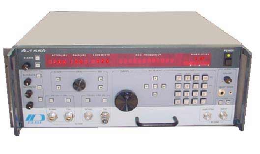
The DSI-1550 operates from 100 Hz to 1 GHz (up to 18 GHz using the Microwave Downconverter option). Extended low frequency of 20 Hz to 1 kHz using system software. The receiver automatically tunes the MDC and displays the tuned frequency. Extended low frequency provides additional bandwidths down to 1 Hz in the sweep mode.
STANDARD IF BANDWIDTHS
-
Bandwidths of:
- 50 Hz, 100 Hz, 200 Hz, 500 Hz, 1 kHz, 2 kHz, 5 kHz, 10 kHz, 20 kHz, 50 kHz, 100 kHz, 200 kHz, 500 kHz, 1 MHz, 2 MHz, 5 MHz, 10 MHz, 20 MHz, 50 MHz,
100 MHz, 200 MHz
An expandable bandwidth set is available below 20 kHz which includes: 250 Hz, 300 Hz, 400 Hz, 640 Hz, 800 Hz, 1.3 kHz, 1.6 kHz, 2.5 kHz, 3 kHz, 4 kHz, 6.4 kHz, 8 kHz, 9 kHz, 13 kHz, 16 kHz. Low Frequency Bandwidths: 1 Hz, 2 Hz, 5 Hz, 10 Hz, 20 Hz.
SELECTABLE TUNING RESOLUTIONS
Arrow keys below the display select the tuning digit. The selected digit blinks. Tuning may be done in a manual step by selecting the step key. The step size is determined by the selected digit. The tuning knob also tunes at the selected digit.
Frequency Resolution of: 0.1 Hz from 100 Hz to 250 kHz, 1 Hz from 250 kHz to 15 MHz, and 100 Hz from 15 MHz to 1 GHz.
Frequency stability of 5 x 10⁻⁸ from an oven-controlled 100 MHz oscillator.
The receiver can be programmed to scan a frequency range without the external computer. Inputs from the keypad for start frequency , stop frequency, and step size may be stored for up to 100 individual sweep tests.
SYNTHESIZER DESIGN employed to provide programmable frequency control. Any frequency may be entered from the keypad with up to seven-digit resolution.
AM/FM DETECTOR SWITCH automatically selects audio source; gain controls provided for headphone use.
AUXILIARY VIDEO output for z-axis display provides a direct connection for video monitoring.
Z-AXIS OUTPUT is provided on the rear panel for "Rastering" of repetitive signals. Automatic remote mode selection by the host computer.
LOW NOISE FIGURE:
- Nominal noise figure of 6 dB.
- Noise floor in a 100 Hz bandwidth of -37 uV.
- Noise floor in a 10 kHz bandwidth of -17 uV.
- 80 dB image rejection over the entire frequency range.
PRESELECTION FILTERS: Six bandpass filters are individually selected during tuning corresponding with the receiver band and tuned frequency.
Filter values are: 200 MHz Low Pass, 200-350 MHz, 350-550 MHz, 550-750 MHz,
750-1000 MHz and 1100 MHz Low Pass.
SPURIOUS RESPONSE: > -120 dBm
Input VSWR:
2.1 maximum
Maximum Tolerated RF Input:
CW (rms): 0.5 watt
Peak: 1,000 watts
1 usec 1 kHz PRF
IF Shape Factor:
Vs. Temperature
Nominally 4:1 (60 to 6 dB)
IF Output Center Frequencies:
21.4 MHz and 1450 MHz
IF Output Level (into 50 Ohms):
+ 10 dBm maximum
AGC Modes:
Off, Fast, Slow
Video Output Impedance:
50 Ohms
Video Output Level (into 50 Ohms):
AM: 3.0 Volts (10V Aux.)
FM: 1.0 Volt P-P Nominal
Audio Detector Functions:
AM, FM, BFO (CW)
Audio Gain Control Range:
40 dB
Audio Output Level:
2.5 Volts (rms) into 8 Ohms
Noise Figure:
Nominally 10 dB
|
Preselecting Filtering:
>Automatic selection as a function
of tuned frequency
AM Detector Dynamic Range:
30 to 35 dB
Clock Frequency Stability (aging rate):
5 x 10⁻⁸ per year
Clock Frequency Stability Offset
5 x 10⁻⁸, 0 to 35oC
Clock Frequency Stability Offset vs Temp.
5 x 10⁻⁸, 0 to 35oC
Operating Frequency Stability:
After 30 minutes warm-up, stability is
equal to clock stability
MTBF:
>3500 hours calculated
>4000 hours field experience
Interface
IEEE-488
Power Requirements
115/230 VAC +/- 10%
50 to 60 Hz, single phase
Audio Bandwidth:
100 Hz to 20 kHz minimum at -3 dB
Dimensions (inches):
7 high x 17 wide x 18 deep
Weight:
45 lbs.
|
|
INPUT CHARACTERISTICS |
| |
RF Input | Two Type-N switch selectable
One BNC isolated for Band 1
|
| VSWR | 2:1, 50 Ohms
|
| Max Input Level | 1 Watt CW
|
| Dynamic Range | >60 dB
|
| Residual Responses | <120 dBm
|
| Input Attenuator | 0-100dB in 10 dB steps
|
| Impulsive Response | <2% Overshoot
|
|
DETECTOR |
| |
Demodulation Modes | AM,FM,CW (BFO), Log-AM
|
| Outputs | Separate AM/FM, Aux. Video and Z-axis
|
| Video Bandwidth | .5 x IF Bandwidth, automatically selected
|
| Pulse Stretcher | Variable 0.1 to 100 usec
|
| Slideback (Squelch) | Continuously Adjustable
|
|
IF FILTERS | Bandwidths (6dB) |
| |
Analog Filters, Linear Phase | 200, 250, 300, 500, 640, 800 Hz
1, 1.3, 1.6, 2, 2.5, 3, 4, 5, 6.4, 8, 10, 13, 16, 20 kHz
|
| Skirt Selectivity | <3:1 (60 to 6 dB)
|
| Impulsive Response | <12% Overshoot
|
Analog Filters, 12 dB Gaussian | 50 Hz, 100 Hz, 50 kHz to 200 MHz in a 1-2-5 sequence
|
| Skirt Selectivity | <4:1 (60 to 6 dB)
|
| Impulsive Response | <12% Overshoot
|
|
FREQUENCY RANGE | 100 Hz to 1 GHz in 3 bands |
|
Band 1 100 Hz to 250 kHz
Band 2 250 kHz to 15 MHz
Band 3 15 MHz to 1 GHz
|
|
FREQUENCY RESOLUTION | 0.1 Hz 00 Hz to 250 kHz |
|
1 Hz 250 kHz to 15 MHz
10 Hz 15 MHz to 1 GHz
1 MHz for bandwidths of 20 MHz or greater
|
|
FREQUENCY TUNING | Numeric Keypad, Up/Down Arrow Keys, or Tuning Knob.
Tuning resolution is selectable in decade steps. |
|
FREQUENCY STABILITY | <5 x 10⁻⁸ (0 to 35oC)
|
|
AGING | 1 ppm/per year |
|
REFERENCE OUTPUT | 20 MHz @ dBm on rear panel |
|
FREQUENCY DISPLAY | 7-digits 0.1 Hz Resolution 20 Hz to 250 kHz
8-digits 1 Hz Resolution 250 kHz to 15 MHz
8-digits 10 Hz Resolution 15 MHz to 1 GHz
|
|