18 March 2001
[79 pages.]
MIL-HDBK-1195
30 SEPTEMBER 1988
AMSC N/A
DISTRIBUTION STATEMENT A. APPROVED FOR PUBLIC RELEASE: DISTRIBUTION IS UNLIMITED
AREA FACR
ABSTRACT
Electromagnetic Interference (EMI) is a description of the phenomenon which results from allowing conducted and radiated electrical signals to reach destinations where their presence is undesirable. Uncontrolled EMI may cause computer malfunction or error, detonation of electrically explosive devices, or be the cause for loss of classified information to an enemy. The objective of this handbook is to provide a basic understanding of the problems associated with the acquisition of a facility containing one or more EMI shielded enclosures. It is intended that only the characteristics of the facility that are unusual in comparison to a nonshielded facility will be addressed. This handbook is a brief introduction to EMI shielding theory, and presents basic criteria of importance during the planning, design, and construction of a typical facility containing an EMI shielded enclosure.
FOREWORD
This handbook has been developed from an evaluation of facilities in the shore establishment, from surveys of the availability of new materials and construction methods, and from selection of the best design practices of the Naval Facilities Engineering Command (NAVFACENGCOM), other Government agencies, and the private sector. This handbook was prepared using, to the maximum extent feasible, national professional society, association, and institute standards. Deviations from this criteria, in the planning, engineering, design, and construction of naval shore facilities, cannot be made without prior approval of NAVFACEWGCOMHQ code 04.
Design cannot remain static any more than can the functions it serves or the technologies it uses. Accordingly, recommendations for improvement are encouraged and should be furnished to Commander, Western Division, Naval Facilities Engineering Command, Code 406.2, P.O. Box 727, San Bruno, CA 94066-0720; telephone (415) 877-7422.
THIS HANDBOOK SHALL NOT BE USED AS A REFERENCE DOCUMENT FOR PROCUREMENT OF FACILITIES CONSTRUCTION. IT IS TO BE USED IN THE PURCHASE OF FACILITIES ENGINEERING STUDIES AND DESIGN (FINAL PLANS, SPECIFICATIONS, AND COST ESTIMATES). DO NOT REFERENCE IT IN MILITARY OR FEDERAL SPECIFICATIONS OR OTHER PROCUREMENT DOCUMENTS.
RADIO FREQUENCY SHIELDED ENCLOSURES
CONTENTS
1.1 Scope
1.2 Responsibilities1.2.1 Chief of Naval Operations
1.2.2 Maintenance Authority
1.2.3 Designer1.3 Policy
1.4 Principal Data Sources1.4.1 Base Electronic System Engineering Plan (BESEP)
1.4.2 Naval Shore Electronics Criteria Handbooks
1.4.3 NAVFAC Design Manuals
1.4.4 Exceptions
Section 2 BASIC ELECTROMAGNETIC INTERFERENCE SHIELDING THEORY
2.1 Introduction2.1.1 Increased Need.for Shielding2.2 Sources of EMI
2.3 Purposes for EMI Shielding2.3.1 Shielding Effectiveness Level2.4 Characteristic's ofEill Waves
2.4.1 Antenna Emissions
2.4.2 Shielding Effectiveness Equation2.5 Shielding Material Characteristics
2.6 Penetrations2.6.1 Waveguide Below Cutoff Penetration Theory
2.6.2 Door Penetrations2.6.2.1 Effect of Construction on Door Shielding
2.6.2.2 Considerations for Door Replacement
2.6.2.3 Door Closure/Seal Comparisons2.6.3 Duct Penetrations
2.6.4 Piping and Conduit Penetrations
2.6.5 Structural Penetrations2.7 Conducted EMI Isolation
2.8 EMI Filters for Electrical Conductors2.8.1 EMI Filters for Electrical Power
2.8.2 EMI Filters for Signal Circuits
2.8.3 Electrical Filter Design Specification Requirements
2.8.4 Insertion Loss Measurements of Electrical Filters2.9 Facility Grounding System
2.9.1 Lightning Protection Subsystem
2.9.2 Fault Protection Subsystem
2.9.3 Signal Reference Ground Subsystem2.10 TEMPEST Shielding Requirements
2.11 Types of Shielding Systems2.11.1 Bolted, Modular Shielded Enclosures
2.11.2 Welded Shielded Enclosures2.11.2.1 Large Welded Structures
2.11.2.2 Warping Due to Welding2.12 EMI Conductive Gasketsp Cements and Tapes
2.12.1 Mesh Gaskets2.13 Fingerstrips
3.1 Introduction3.1.1 Construction Reguirements
3.1.2 EMC Surveys and Studies3.2 Types of Shielded Enclosures
3.2.1 TEMPEST
3.2.2 High Altitude Electromagnetic Pulse (HEMP)
3.2.3 Hazards of Electromagnetic Radiation to Personnel (HERP)
3.2.4 Hazards of Electromagnetic Radiation to Ordnance (HERO)
3.2.5 Hazards of Electromagnetic Radiation to Fuel (HERF)
3.2.6 Shielding for Communication-Electronics (C-E) Facilities3.3. Electromagnetic Compatibility (EMC) Evaluation
3.4 Base Electronic System Engineering Plan (BESEP)
3.5 Types of Construction for EMI Shielding3.5.1 Demountable Enclosures
3.5.2 Welded Enclosures
4.1 Introduction
4.2 Predesign
4.3 Architectural Design4.3.1 Comparison of Various Seals
4.3.2 Vestibule/Threshold Protection
4.3.3 Size and Location of Power Filters
4.3.4 Shielding of Access Penetrations4.4 Structural Design
4.5 Mechanical Design4.5.1 Minimizing and Shielding Mechanical Penetration4.5.1.1 Dimensions and Materials for Shielding Mechanical Penetrations4.6 Fire Protection Design
4.7 Electrical Design Considerations4.7.1 Design Allocations for Power Filters4.8 Specification Design Considerations
4.9 Testing4.9.1 Shielding Effectiveness Leak Detection System (SELDS)
4.9.2 Testing After Shielding Completion
4.9.3 Testing Before Finish is Installed4.10 Cost Considerations
4.11 Design Review4.11.1 Review of Drawings
5.1 Introduction
5.2 Submittals5.2.1 EMI Test Module
5.2.2 Supervision of Construction5.3 Installation
5.3.1 Panels5.3.1.1 Weather Protection During Construction
5.3.1.2 Requirements for Clean and Tight Seams
5.3.1.3 Foundations and Ceilings5.3.2 Penetrations
5.3.3 Doors5.3.3.1 Doorframe Contact Surfaces5.3.4 Waveguide-type Air Vents
5.3.5 RFI filters
5.3.6 Grounding5.4 Testing
5.4.1 Leak Detection Systems
LIST OF FIGURES
1 RF Door and Wall Seam Type Cross-sections
2 Preferred Waveguide Air Vent Filter, Bolted and Welded Enclosures
3 Typical TEMPEST Pipe Penetration, Bolted and Welded Enclosures
4 Single Skin Bolted Enclosure Penetration Panel
5 Waveguide Fluid Attenuator Insert, TEMPEST Piping Penetrations
6 RF Bolted Floor Drain Penetration With Attenuator Insert
7 RF Shielding of Interior Steel Column Penetration
8 RF Shielding, Interior Reinforced Concrete Column Penetration
9 RF Shielding, Exterior Concrete Column
10 TEMPEST Required Filter Insertion Loss
11 TEMPEST Signal Filter Attenuation Requirements, Measured With Matched Source and Load Impedances
12 High Frequency Grounding, Using Raised Flooring as an Equipotential Plane
13 Low Frequency and Power Grounding Within a Shielded Enclosure
14 Single Entry Ground Stud Penetration in a Bolted Plate Assembly
15 TEMPEST Required Shielding Effectiveness
16 Welded RF Shielding of Wall Section
17 RF Wall Shielding Seam Detail
18 RF Shielding Wall-ceiling Section
19 RF Shielding, Vault Ceiling to Interior Wall Section
20 RF Shielding, Sliding Door Frame Section
21 RF Shielding, Interior Wall-floor Intersection With Electrical Isolation Underlayment
22 RF Shielding, Interior Wall-floor Intersection an Tubular Frame
23 RF Shielding of Floor-wall Intersection, With Overlap Seams
24 RF Shielding of Floor, Layout
25 RF Shielding of Roof, Layout, With Metal Decking
26 Anchoring of Steel Floor Plates With Electrical Isolation
1.1 Scope. MIL-HDBK-1195 establishes specific criteria for the design and construction of shielded enclosures. The Design Manual 12.1, Electronic Facilities Engineering, establishes the general criteria for the design of Electronic Facilities. The Design Manual 12.02, High Altitude Electromagnetic Pulse Protection for Ground-Based Facilities, establishes the general criteria for protection of ground base facilities from high altitude electromagnetic pulse (HEMP).
THIS HANDBOOK SHALL NOT BE USED AS A REFERENCE DOCUMENT FOR PROCUREMENT OF FACILITIES CONSTRUCTION. IT IS TO BE USED IN THE PURCHASE OF FACILITIES ENGINEERING STUDIES AND DESIGN (FINAL PLANS, SPECIFICATIONS, AND COST ESTIMATES). DO NOT REFERENCE IT IN MILITARY OR FEDERAL SPECIFICATIONS OR OTHER PROCUREMENT DOCUMENTS.
1.2 Responsibilitles. The design and construction of Navy shielded enclosures require close coordination between the designer and other parties, Responsibilities involved in design stages are as follows:
1.2.1 Chief of Naval Operations. The Chief of Naval Operations (CNO) is the Director of Naval Communications, who sponsors and supports Naval communication facilities through the Naval Telecommunications Command and other commands. The CNO, as the user, states the needs of the operating forces to the producer organizations. Such needs can include operating and supporting facilities, research and development, improved equipment, new equipment, spare and repair parts, consumable, training maintenance, personnel facilities, and any other requirements of the user. In-many instances, the CNO is responsible for supporting the Defense Communication Agency (DCA), which is the sponsor for the nation's world wide Defense Communication System (DCS). Within the Chief of Naval Operations, electronic engineering capabilities are concentrated in the Space and Naval Warfare Systems Command (SPAWARSYSCOM), while facility design and construction capabilities are assigned to the Naval Facilities (NAVFAQ Engineering Command. Specific responsibilities of these commands are assigned as follows:
Commander Space and Naval Warfard System Command (COMSPAWARSYSCOM) is responsible for:
a) Providing guidance and direction in electronics matters from project Inception to completion.b) Providing electronic technical support both within and outside the Chief of Naval Operations.
c) Obtaining sponsor statements of operational requirements and translating them into statement of resource requirements.
d) Designing and/or selecting electronic systems, equipment and ancillary devices. Initiating procurement and distribution action for these items and installing equipment. On a military construction (MILCON) project, project execution for such equipment installation will be determined in conjunction with NAVFAC.
e) Performing overall project direction functions for assigned projects.
f) Performing project execution functions for the electronics aspects of assigned projects.
g) Providing NAVFAC with specialized technical electronics support when necessary for the successful prosecution of the facility efforts.
h) Budgeting for or securing funding ampport of electronic design and Installation where MILCON funding is not applicable.
i) Funding and development of Base Electronic Systems Engineering Plans (BESEPS) for all approved MILCON projects.
j) Planning, coordinating, monitoring and implementing the complete installation where electronic equipment installation involves more than one Systems Comand and or Program Manager (SYSCOM/PM). This responsibility includes identification of requirements, electronics design compatibility, monitoring of resources to ensure proper tasking by the commands, identification of problem areas, timely completion of the total electronic equipment installation, and.to act as a single point of contact for NAVFAC on all shore electronics matters.
Commander, Naval Facilities Engineering Command (COMNAVFACENGCOM) is responsible for:
a) Providing technical guidance and direction in all shore facilities engineering matters from project inception to completion.b) Providing Naval shore facilities technical support.
c) Performing overall project direction functions for assigned projects.
d) Performing project execution functions for facilities aspects of all projects.
e) Providing SPAWARSYSCOM with contractual and facilities engineering support (such as award of installation contracts and provision of Resident Officer in Charge of Construction (ROICC) services).
1.2.2 Maintenance Authority. SPAWARSYSCOM exercises technical control through regional and district offices, whose responsibilities include installation and maintenance engineering of electronic equipment that is beyond the capacity of station forces. Regional and district offices represent SPAWARSYSCOM for electronic control while the architect-engineer develops the design.
1.2.3 Designer. The architect/engineer (A-E) or equivalent Navy personnel (hereafter called "the designer") usually enters design development after the operational requirement has been established and before actual construction begins. The designer plans the building to satisfy the operational requirements normally set forth in the BESEP and prepares project drawings and specifications under the control of NAVFAC and the guidance of SPAWARSYSCOM. Requirements for military construction and special projects that do not directly involve electronic equipment, and thus do not require a BESEP, are identified in project documentation. The designer must maintain close liaison with the KAVFAC command responsible for the particular project, which will coordinate all technical matters with the sponsors and users of the project.
1.3 Policy. The design of electronic facilities should be based on operational requirements. The primary consideration is that operational communication buildings and other electronic facilities be sited, arranged, and constructed to provide the most effective commmications, possible. Whenever compromises between operational requirements and convenience, cost, or energy conservation become necessary, such compromises should be resolved in favor of operational requirements. Where there is conflict between two mandatory Government documents, the more stringent requirement governs. In all cases, the BESEP shall be the overriding document.
1.4 Principal Data Sources
1.4.1 Base Electronic System Engineering Plan (BESEP). The basic document used by SPAWARSYSCOM for planning and controlling shore station electronic installation work is BESEP. It translates operational requirements into a detailed technical plan for meeting the requirements. It is prepared by representatives of SPAWARSYSCOM, in collaboration with NAVFAC, and is approved by the sponsor for use in design deyelopment. A detailed description of the BESEP, as well as policy and procedures for its use, is provided in SPAWARSYSCOM Instructions, but the BESEP generally provides the following information:
a) General Requirements. The BESEP establishes the requirements of the project, the scope and layout of the planned facility, the design and installation of the electronic system, information on the electronic equipment to be used, details of system checkout, and characteristics of the physical plant.b) Design Data. The BESEP includes information addressing the following considerations:
1. structural limitations;2. recommended locations of electronic equipment, power panelboards, special red or black panelboard designationsi and special power requirements;
3. identification of red areas;
4. antenna locations and the number, type, performance, and frequency ranges required;
5. cable types and termination locations;
6. radio-frequency (RF) shielding requirements, other requirements for precautions against radiation hazards, and characteristics of the source of radiation;
7. electronic equipment areas of concentrated heat load and requirements for special air conditioning or environmental control;
8. recommended locations of compressed air outlets, specifying pressure and valve requirements;
9. grounding systems;
10. and internal security.
Requirements relevant to the specific site and supporting facilities are also included. The completeness of such information and the amount of detail furnished to the designer depend an the circumstances of the project, and in emergencies, may be brief and subject to augmentation as the project progresses.
1.4.2 Naval Shore Electronics Criteria Handbooks. These handbooks will aid the NAVFAC design agent in understanding the mission of the facility. The series provides background information and planning and technical criteria for design of electronic facilities. All referenced volumes included in the series are listed in references. The first six volumes address major considerations for selecting, designing, installing, and supporting general electronic facility systems. The subsequent volumes address specific kinds of systems.
1.4.3 NAVFAC Design Criteria. The design criteria series presents criteria for the design of facilities under the cognizance of the Naval Facilities Engineering Command. The NAVFAC design criteria referenced in this handbook are listed in references.
1.4.4 Exceptions. Normally, a project BESEP is prepared for shore electronic projects. On occasion, however, a project may involve electronic equipment installations even though a formal BESEP is not available to establish facility requirements. The majority of these projects are under the cognizance of the Commander, Naval Air System Command (COMNAVAIRSYSCOM), Commander, Naval Sea System Command (COMNAVSEASYSCOM), Chief of Naval Education and Training (CNET) or Commandant of the Marine Corps (CMC), and facility data are available from the major claimant command. Equipment manufacturers of many large systems (i.e. fire control, weapons, simulators, etc.) supply facility requirement manuals as part of their contracts.
2.1 Introduction. The use of sophisticated communication and electronic equipment has increased drastically in recent years to meet the operational requirements of the Navy. The solid state electronic components of the modern equipment are susceptible to upset or damage from external electromagnetic source caused by induction of unwanted electrical currents and voltages in the connecting circuitry. The high speed switching (baud rate) of recently utilized equipment is capable of emitting electromagnetic signals in a broad frequency range. The acquisition of these signals by unauthorized signal detection equipment may result in the compromise of sensitive information if the equipment emitting the signals are processing decoded classified information.
2.1.1 Increased Need for Shielding. NAVFAC has been tasked to design and construct facilities with shielded enclosures to provide proper protection for communications and electronics equipment. As a result of a greatly increased size and complexity of communications and information processing systems, the size of necessary shielded enclosures has increased dramatically, with many system floor space requirements exceeding 20,000 ft2 (1,858 m2). In addition to increased size, the frequency range and shielding effectiveness requirements have also been expanded resulting in a greater complexity in the shielding construction design. This results from necessary accommodation of numerous penetrations, structural interconnections, thermal expansion and contraction, and electric isolation requirements, on a larger scale than previously experienced with free standing shielded enclosures. As a result, the problems associated with design, construction, and testing of the shielded enclosures have substantially increased.
2.2 Sources of EMI. When the problems associated with Electromagnetic Interference (EMI) were first encountered and investigated, the phenomenon was identified as Radio Frequency Interference (RFI). Earlier, the bulk of the problems were with radio communications systems transmission and reception. With modern expansion of the use of signal processing, military and industrial electronics systems, the broader Electromagnetic Compatibility (EMC) terminology is used. In addition to deliberate radio communications sources of interference, we must consider digital switching and solid state power supplies, high intensity discharge (HID) lighting systems, automotive ignition, electric motor switching, arc welding, electrical power system faulting and switching, corona and static discharge, intermittent contact between metal objects in an electromagnetic field, lightning discharges, fluorescent lighting, and intermodulation products from nonlinear junction mixing, are among the many sources of this problem.
2.3 Purposes for EMI Shielding. There are basically two purposes for providing EMI shielding in military construction projects. The first is to prevent external EMI sources from penetrating a sensitive environment. This sensitive environment may contain electronic equipment, personnel, ordnance, or fuel supplies which are susceptible to the presence of EMI. This type of shielding is for Electromagnetic Compatibility (EMC). The second purpose for shielding is to prevent electromagnetic signals generated from certain electronics equipment within the facility from being transmitted or conducted outside the controlled area in sufficient magnitude to be received and recorded by the most sensitive receiving and signal recovery systems.
Specifically, when electronic equipment is being used to process, display, or store plain language (decoded) text of classified information, the shielding utilized to prevent its compromise is called TEMPEST shielding. If the equipment within the shielded facility is not used to process classified information, but it is necessary to prevent the EMI generated by the equipment from being transmitted outside where it can affect the operation of sensitive equipment the purpose of the shield again is for EMC. An example of the latter situation is a medical laboratory facility with large magnitude EMI generating equipment such as the CAT scanner, Nuclear Magnetic Resonators, or Linear Accelerators operating adjacent to signal processing computers. This manual will address design, specification, construction and testing problems associated with shielding for both TEMPEST and EMC. Refer to Naval Shore Electronics Criteria Handbook, NSWSG 0101, 106, Electromagnetic Radiation Hazards for guidance on Hazards of Electromagnetic Radiation to Personnel (HERP), Ordnance (HERO), or Fuel (HERF) shielding. Refer also to NAVFAC DM 12.02, for shielding criteria for electromagnetic pulse (EMP) protection from high altitude nuclear detonations. Whether the purpose for the EMI shielded enclosure is to prevent EMI from entering or leaving the enclosure, the problems and solutions used in the design and construction are basically the same. TEMPEST shielding requirements however, are slightly more complex than EMC shielding requirements and will be described later in the following sections.
2.3.1 ShieldIng Effectiveness Level. The shielding effectiveness (SE) level in decibels (dB) that must be provided and the frequency range over which it is necessary is the first shielding requirement to be determined during the initial planning phase of a project. The available shielding effectiveness is dependent on a number of parameters including frequency, the intrinsic electrical properties of the chosen shielding material, and the number and configuration of discontinuities in the shielding material, which will be necessary to accommodate personnel, (access doors and hatches), equipment installation (piping, conduits, HVAC duct penetrations) and the interface with the parent building construction (columns, beam penetrations, and grounding). Propagation of the EMI may be radiation and conduction, and the required SE must be provided for the total shielding systems including all discontinuities and attachments.
2.4 Characteristics of EMI Waves. An electromagnetic (EM) wave is an energy field which radiates from a source and propagates through a surrounding medium such as air. An EM wave may also be conducted from one point to another by means of conductors arranged to form a transmission line. The EM wave Is composed of an electric field component (K) in volts/meter and a magnetic field component (H) in ampere-turns/meter. The ratio of the (E) field to the (H) field is called the wave impedance (Z = E/H) in ohms. The (E) and (H) fields are time-varying due to a continuous reversal of the polarity of the field cbmponenta propagating in the medium, or a reversal of currents and voltages propagating along a transmission line. The rate at which the field, voltage, or currents alternate with time is called the frequency of the wave and is measured in Hertz (cycles per second). The relationship between frequency (f), velocity of propagation (v), and wavelength (g) (the distance the wave travels during one cycle of oscillation) is:
EQUATION: f = v/g (1)
where
f = frequency
v = velocity of propagation
g = wave length
In free space the velocity (v) is equal to the velocity of light (c), where c = 3 x 10⁸ meters per second. In a dielectric material such as that found in many coaxial transmission cables, the velocity (v) is equal to the velocity of light (c) divided by the square root of the relative permittivity also called the dielectric constant (kr).
2.4.1 Antenna Emissions. The EM wave is generated by means of alternating current or voltage sources driving radiating antennas, which typically consist of metal conductors formed In loops, or linear lengths of conductors such as rod antennae placed above a reflecting plane, or dipoles. It should also include pairs of parallel conductors forming transmission lines. Leaks in the surface of shielded enclosures such as holes, cracks, poor seam closures, or untreated metallic penetrations can act as radiation source loops, dipoles, or transmission lines to transfer electromagnetic waves from one side of electromagnetic shielding to the other, when excited by alternating currents and voltages. The result of exciting loop and dipole antennae, and transmission lines is a combination of both radiated and nonradiated electromagnetic fields surrounding the source antennae. Close to loops and dipoles in a region known as the near field, the nonradiated portion of the electric and magnetic fields are very strong and fall off inversely as the cube of the distance from the antennae. The electric dipole provides a strong electric field close to the antenna and the magnetic loop provides a strong magnetic field. The near field extends to a distance (r) in meters equal to the wavelength in meters divided by 2pi., i.e. r = g/2pi. Beyond the near field is a transition region where nonradiated fields are diminishing and the radiated fields are more significant which extends to about 1.6 times the wavelength, in meters. Beyond the transition region is the far field where the radiated waves are plane waves, i.e. the electric and magnetic field vectors are at right angles to each other and to the direction of wave propagation. Here the wave impedance (Z) is that of free space (377 ohms).
2.4.2 Shielding Effectiveness Equation. Shielding Effectiveness (SE) is defined as 10 times the log to the base 10 of the ratio of the incident electromagnetic power (P1) without the shielding, to the transmitted power (P2) with the shielding in place, expressed in decibels (dB) or:
EQUATION: SE = 10 log (P1/P2) dB (2)
where
P1 = incident electromagnetic power
P2 = transmitted power with shielding in place (in dB)
Since the power can be expressed in terms of wave impedance (Z) and either electric or magnetic fields (E or H), the expression for shielding effectiveness can be further expressed as:
EQUATIONS: SE = 10 log[(E12/Z1)/(E22/Z2)] dB (3)
SE = 10 log[(H12/Z1)/(H22/Z2)] dB (4)
where
P1 = E12/Z1 = H12/Z1
P2 = E22/Z2 = H22/Z2
E1 = Incident Electric Field
E2 = Transmitted Electric Field
H1 = Incident Magnetic Field
H2 = Transmitted Electric Field
When the wave impedance Z of the incident and transmitt - ed electromagnetic field is the same with and without the shielding in place the expression for SE reduces to its familiar form:
EQUATIONS: SE = 20 log (E1/E2) dB (5)
SE = 20 log (H1/H2) dB (6)
2.5 Shielding Material Characteristics. When an electromagnetic wave encounters an enclosing conductive material shield, the portion of the wave transmitted beyond the shielding barrier is reduced in magnitude by both reflection and absorption by the shielding material. The reflection loss occurs at the two interfaces between the transmitting medium (typically air) and the shielding material (typically a conducting metal such as sheet steel, copper, or aluminum). The absorption takes place as the wave passes through the conductive material. The absorption loss in the wave energy results from dissipated heat loss by currents induced in the conductive material by the electric and magnetic fields of the wave passing through. The reflection loss occurs because of the mismatch in wave impedance between the propagating medium and the conductive material. The relationship for shielding effectiveness of a conductive material is typically expressed as follows:
EQUATION: SE = [R + A + C] dB (7)
where
R = reflection loss
A = absorption loss
C = correction term for re-reflection within the metal surfaces
The correction term (C) is usually of small magnitude and ignored when the absorption loss (A) is greater than about 10 dB.
The reflection loss (Rp) for plane waves impinging on shielding material is:
EQUATION: Rp = (168 - 20 log (fmr/gr)0.5] dB (8)
where
Rp = Reflection loss for plane waves
mr = Permeability relative to copper
gr = Conductivity relative to copper
f = frequency in Hz
The reflection loss (Rm) for the magnetic loop measurements in the near field is:
EQUATION: Rm = 20 log [(.0117/[rfgr/mr]0.5)+(5.35 r [fgr/mr]0.5)+.354]dB (9)
where
r = Distance from source to shield in meters
The reflection loss (RE) for the electric dipole measurements in the near field is:
EQUATION: RE = (322-10 log ([mrf3r2]/gr)] (10)
The absorption loss (A) is a simpler relationship, not dependent on the antenna used, but directly proportional to material thickness (d) in meters.
EQUATION: A = [131.4 d(fmrgr)0.5] dB (11)
where
d = Thickness of shield material in meters
For metal foil shields at low frequencies where the absorption loss (A) is minimal, (less than.about 10 dB), ihe correction factor for re-reflections within the shield (C) must be considered. The correction factor (C) is:
EQUATION: C = 20 log [i - G 10-A/10(cos[0.23A] - j sin [0.23A])] dB (12)
where
G = Reflection coefficient
A = Absorption loss
,Here (A) is the shield absorption loss, and (G) is the dimensionless two-boundary reflection coefficient. In the foregoing equations the various coefficients are identified as follows:
EQUATIONS: mr = m/mo (13)
gr = g/gcu (14)
where
mr = relative permeability of the shielding material with respect to that of free space.mo = permeability of free space, equal to 4pi x10-7 henries per meter.
gr = relative conductivity of the shielding material with respect to that of copper.
gcu = conductivity of copper in equal to 5.8 x 10⁷ mhos per meter).
Reference is made to the following tables and graphs from chapter 8 of MIL-HDBK-419, Grounding, Bonding. and Shielding for Electronic Equipments and Facilities, Volume I:
| TABLE | SUBJECT |
|
| 8-1 | Table of conductivity, permeability and aborsoption loss of 21 different shielding materials at 150 kHz. | |
| 8-2 | Table of permeability and absorption loss of iron, copper, and aluminum shields, 1 mm thick versus frequency (60 Hz to 10 GHz). | |
| 8-4 | Table of permeability and H-field, E-field, (in the near field), and plane wave reflection losses for iron, copper, and aluminum shields versus frequency (60 Hz to 10 GHz) with a source to shield separation of one foot. |
2.6 Penetrations. The theoretical shielding effectiveness of a large variety of conductive metal materials would appear to provide sufficient dB of SE to be available for construction of 100 dB enclosures if it were possible to use the infinite sheet values utilized in the theoretical equations for reflection and absorption. Unfortunately, the ideal enclosure formed from a seamless envelope of metallic material with no openings or perietrations is not a reality. The obtainable overall SE for both welded and bolted seam steel enclosures, soldered and bolted copper enclosures, and bolted and welded aluminum enclosures is severely limited by first, the door closures, second, bolted or gasketed seams, third, penetrations by metal conductors, and fourth, the wave guide below cutoff air duct, vent and drain penetrations. Beyond this, cracks in welds, corrosion of seam metal-to-metal mating surfaces, and uncontrolled penetration by fasteners such as screws,. nails, or bolts add to the degradation from the theoretical or ideal SE of a shielding material.
2.6.1 Waveguide Below Cutoff Penetration Theory. It is possible to provide penetrations which will pass light, air, or liquids through the shielding surface without passing electromagnetic waves lower in frequency than a certain fixed value by means of an effect called waveguide below cutoff. Waveguides are formed by metal tubing or ducting and are used to deliberately propagate electromagnetic waves in transverse-electric (TE) modes and transverse magnetic (TM) modes for wave frequencies above a cutoff frequency (fc). At frequencies which are below the cutoff frequency the waveguides attenuate the wave energy. For circular waveguide metal piping, the lowest cutoff frequency is:
EQUATION: fc = [6929/D] MHz (15)
where
D = waveguide diameter in inches.
The attenuation for frequencies below the cutoff frequency is given by:
EQUATION: SE = [31.9L/D [1 - (f/fc)2]0.5] dB (16)
where
L = length in inches
f = frequency
fc = cutoff frequency.
For rectangular ducting with width (a) and height (b) and with width greater than height, the cutoff frequency is:
EQUATION: fe = (5906/a) MHz (17)
where
a = longest dimension in inches.
The attenuation for the rectangular duct for frequencies below the cutoff frequency is given by:
EQUATION: SE (27.3L/a [1 - (f/fc)2]0.5) dB (18)
When the expression under the radical for the square of the frequency divided by the cutoff frequency is less than 0.1 (when f is less than 1/3 fc) it can be neglected, and the expressions for SE become:
EQUATION: SE = (31.9 L/D) dB (19)
for circular waveguides and
EQUATION: SE = (27.3 L/a) dB (20)
for rectangular waveguides.
2.6.2 Door Penetrations. Doors are required for personnel and equipment
access in the shielded enclosure. They are the largest openings in the shielded
enclosure, and are the most easily damaged through daily use. They are the
weakest link in the overall shielding system. The doors must be constructed
of shielding material in such a way as to provide SE equal to or greater
than the remainder of the enclosure. There are several basic types of door
closures currently used in shielding construction, several of which are seen
in Figure 1. These include the pneumatic bladder type, the compressed rows
of beryllium-copper fingerstock types, the knife edge guillotine type, and
the magnetic strip type door. The fingerstrips are also used in the knife
edge type doors, but do not receive the same compression and wiping forces
that fingerstrips around the door periphery which are compressed between
overlapping door and frame surfaces do, but they do have an added labyrinth
presented to induced currents, penetrating from the outside to inside surfaces
at the closure. With newly brightened fingers and their mating surfaces,
proper adjustment of hinges and cams to provide even compression around the
closures at the outer edges, most available types of doors will meet the
requirements of MIL-STD-285, Method of Attenuation Measurements for
Enclosures, Electromagnetic Shielding, for Electronic Test Purposes,
and NSA 65-6, National Security Agency Specification for RF Shielded
Enclosures for Communications Equipment: General Specification, especially
if the plane wave measurements are made with the receiving antenna one foot
from the surface. Knife edge types require a maintenance schedule an the
order of monthly, and compression of fingerstrip types typically bi-annually
require some cleaning and replacement. The pneumatic expansion sliding door
can be obtained with automatic opening and closing, or simply with manual
operation and automatic pressurization of the bladder when the door engages
the stop. Release of the bladder pressure is accomplished upon the actuation
of a door release valve. The pneumatic door provides the highest level of
SE of all the door types, utilizes no fingerstrips or gaskets, but occasionally
requires replacement of the pneumatic bladder.
Figure 1
RF Door and Wall Seam Type Cross-section
2.6.2.1 Effect of Construction on Door Shielding. Some shielding manufacturers refuse to guarantee performance of their door and door frames in shielding provided by others, unless they are in control of the door installation. In the construction of welded enclosures, the welding of the door frame into the parent shielding can easily result in warping and twisting of the door frame with a resulting misfit and failure of the door to provide the required shielding performance. In both bolted and welded shielding construction the installation of the doors and frames prior to compietion of the remainder of the construction usually results in damage to fingerstock, door mating surfaces, and can also result in the bending and denting of the door sills. Protective coverings must be provided to protect delicate door surfaces and fingers during construction. Other hazards degrading closing surfaces during construction are uncontrolled welding splatter, any mis-applied paint finishes, and surface preparation and conditioning materials.
2.6.2.2 Considerations for Fingerstock Replacement. Because of the delicate nature of fingerastock materials, the door design should provide for rapid and easy replacement of fingerstock without the requirement for special tools and soldering. Pneumatic doors, which are all of the sliding type, must have available a pocket with a removable cover so that the door can be serviced or removed. The use of dissimilar metals or metal finishes should be minimized in door design because of the possible battery action and corrosion which occurs In the presence of any moisture.
2.6.2.3 Door Closure/Seal Comparisons. Door latching mechanisms must be designed to provide uniform wiping and compression of the fingerstock with enough force to provide the required shielding effectiveness. They must also allow quick egress to satisfy the requirements of governing National Fire Protection Association (NFPA) rules and regulations. The pneumatic type door, even with automatic opening and closing, requires the longest opening time, typically seven or more seconds. The Army Corps of Engineers Civil Engineering Laboratory Technical Report M-313, April, 1983, Study of EMI/RFI Seals on Shielded Enclosure Personnel Access Doors, provides an experimental analysis of EMI door sealing mechanisms which indicates that wedge and knife edge type doors degrade as much as 15 dB in as little as 4 months due to routine use and exposure. The magnetic strip type of door is new, and little long terms data is available. The brass shimstock material covering the magnets tends to oxidize rapidly, and a maintenance schedule similar to knife edge doors is projected. A further problem projected for the magnetic strip doors is the work hardening and eventual cracking of the brass shimstock which holds the individual magnets in place.
2.6.3 Air Duct Penetration. The second largest openings in shielding
are intake and exhaust of air ducting in heating, ventilation, and air
conditioning (HVAC) of the enclosures. In order to maintain the required
shielding effectiveness through frequencies as high as 10 GHz, a waveguide
below cutoff air filter must be placed in the duct penetrations through the
shielding. The waveguide filter may be a standard shielding manufacturer
product, typically a brass or steel core, tin-dipped, which may be similar
in appearance to a honeycomb with the walls of each small cell continuously
welded or soldered to the next cell. Waveguide or honeycomb assemblies are
soldered in a parent framework, which is then welded or bolted into the shield,
see Figure 2. The attenuation characteristics for each individual cell must
exceed the shielding effectiveness requirements of the total enclosure. The
static pressure drop that the waveguide filter causes in the airstream must
be included in the HVAC calculations, as well as being specified and controlled
in the governing specifications. The use of radio frequency (RF) gasketing
materials in the assembly and closure of the air filter should be expressly
forbidden by the written specification. Dissimilar, and electrochemically
active combinations of metal surfaces should also be prohibited In this location
where severe corrosion can be accelerated by the combination of mechanical
vibration, air flow, possible moisture, and changing temperatures at
metal-to-metal interfaces. Filter honeycomb inserts required for MIL-STD-285
and NSA 65-6 shielding requirements are typically one inch in depth, with
individual cell openings of 1/4 in. (6.3 mm) or less. Custom made units may
have clusters of larger diameter metal tubes, continuously bonded at the
end of a shielding plate, with hole sizes up to 1/2 in. (12.7 mm) diameter
for MIL-STD-285 and NSA 65-6 required shielding effectiveness at 10 GHz.
Figure 2
Preferred Waveguide Air Vent Filter,
Bolted and Welded Enclosure
2.6.4 Piping and Conduti Penetrations. Numerous penetrations in an
enclosure are required for electrical conduits (power, telephone, alarm,
etc.), and for mechanical piping (chilled water, fire sprinkling vents and
drains). The TEMPEST requirement for an electrically isolating section six
inches in length, within two inches from the shielding surface tends to
complicate the selection of the penetrating piping materials. Schedule 80
PVC with standard fittings are readily available with reasonable temperature
and pressure ratings (2 in., 295 psi at 68º F, or 51 mm, 2034 KPa at
20º C, for example). For higher temperatures, schedule 80, PVDF can
be used (rated at 300º F or 149º C). The penetration through the
shielding must be metal, and continuously bonded electrically around the
periphery of the penetration to the shielding (welded or brazed) as seen
in Figures 3 and 4. Clamped or threaded penetrations, and those using RF
gaskets are not projected to provide long term electrical continuity because
of oxidation and corrosion of closure contact surfaces under normal environments.
These nonpermanent types of penetrations should be prohibited in the written
specifications. The metal piping penetrations will provide waveguide below
cutoff attenuation for frequencies below their cutoff frequency. For piping
larger than 1/2 in. (12.7 mm) I.D. and with NSA 65-6 requirements for attenuation
at 10 GHz, a waveguide filter insert may be required, as seen in Figure 5.
Where the piping has continuously welded, brazed or soldered joints in the
run from the penetration to the equipment within the shielded enclosure,
or where the piping has tight threaded couplings, the filter insert may not
be needed. For short runs to the penetrations typical of the air vents and
roof or floor drains, the insert is usually required. The waveguide attenuation
piping insert will be a honeycomb comprised of steel or brass, tin-dipped,
or else stainless steel or brass disk with clusters of drilled holes, as
seen in Figure 6. The filter insert unit will be soldered, brazed, or welded
to the piping. Large diameter piping for fire sprinkler systems within the
enclosure are typically assembled with a nonconductive gasketed joint, and
will require a filter insert. Generally the piping penetration in the shielding
is first fitted with a brazed or welded collar of steel to provide a transition
between the typically thin shielding material and the heavier walled piping,
as seen in Figures 3 and 5. The collar also allows for cutting of the necessary
penetration hole in the field for welding on site without close tolerance
requirements on the hole dimensions. The waveguide filter piping insert will
cause a pressure drop in the flow of liquid which must be considered in their
design. National Fire Protection Association regulations may require the
addition of refractory materials around electrical isolation sections of
piping used with TEMPEST requirements (typical of the fire sprinkling
penetration).
Figure 3
Typical TEMPEST Pipe Penetration,
Bolted and Welded Enclosure
Figure 4
Single Skin Bolted Enclosure Penetration Panel
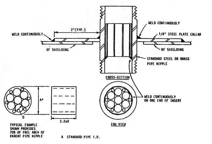
Figure 5
Waveguide Fluid Attenuator Insert, TEMPEST Piping Penetrations
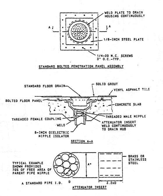
Figure 6
RF Bolted Floor Drain Penetration with Attenuator Insert
2.6.5 Structural Penetrations. A major shielding penetration is the
supporting column for ceiling or roof beams. This can be treated by several
different methods. For TEMPEST enclosures the best electrical isolation between
the shielding and the column is obtained by either isolating the column within
the shielding, as seen in Figure 7, or by totally enclosing the penetrating
column in the shielding material with sufficient distance or nonconducting
material provided to result In the necessary electrical isolation as shown
in Figures 8 and 9. A minimuin of 1-in. of air space is recommended between
the column and the enclosing shield. If single point grounding of the shield
is not a requirement, the penetrating column may be treated by continuously
welding penetrating members such as reinforcing steel or steel beams to the
floor or ceiling shielding sheets. Transition collars or sections are typically
required to weld thin shielding sheets to heavier metal beam penetrations
as shown in Figure 7. With the large shielded enclosures built as an outer
or inner liner for the building construction, the beam structure members
are typically required to penetrate the shielding in many places. The design
of the shielding must accommodate the expansion and contraction of large
metal surfaces pinned at the penetrations to large structural members that
are fixed in position. Expansion joints may be required in the shielding
membrane for both vertical and horizontal motion so that connection with
heavier members don't result in cracking of welds during thermal expansion
and contracting, especially while the construction is exposed to the exterior
environment.
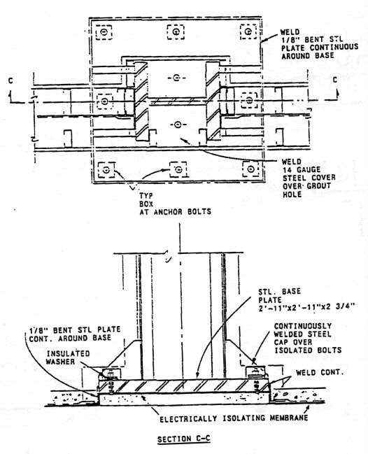
Figure 7
RF Shielding of Interior Steel Column Penetration
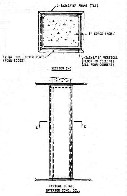
Figure 8
RF Shielding, Inteior Reifnorced Concrete Column Penetration
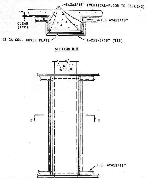
Figure 9
RF Shielding, Exterior Concrete Column
2.7 Conducted EMI Isolation. As stated earlier, the shielded enclosure must provide attenuation of both radiated and conducted electromagnetic field energies. Shielding surface discontinuities such as cracks, holes, poorly tightened bolted seams, or metal piping penetrations may act as slot antennas, loop sources or transmission lines radiating or conducting electromagnetic energies from the inside of the shielding membrane to the outside. The discontinuities required in the construction of a six sided enclosure with its necessary entrances and penetrations are the usual source of electromagnetic leaks. These leaks will cause differences of potential to occur on the outer surface of the shielding. When metal penetrations such as piping and conduits are not provided with an electrical isolating section on the exterior of the shielding which disrupts electrical connection to possible ground returns, the differences of potential caused by the leaks will cause currents to flow in the attached conductors. These induced currents may then be transported or propagated into uncontrolled areas where unauthorized access is possible. Where conduits carrying wiring pass from one shielded enclosure into adjacent enclosures and pass through uncontrolled space, they should be provided with electrically isolating sections on at least one end, and electrical filters on each shielding Penetration. If the conduit with contained wires passes from one shielded enclosure to another through controlled space, it may be possible to use conduit with welded joints, no electrical filters, but a single point ground on only one of the enclosures.
2.8 EMI Filters for Electrical Conductors. All of the electrical service
conductors which penetrate the electromagnetic shielding surface, such as
power, signal, telephone, control and alarm must be provided with electrical
filters. Typical insertion loss requirements in dB as a function of frequency
to be specified for these filters are shown in Figure 10. These filters are
best located at the conductor penetration locations, either inside or out,
depending usually on available access or space. If they must be mounted remotely
from the shielding surface, then runs of continuous metal conduit (threaded
ferrous with welded joints, preferred) must be provided from the filter to
the shielding penetration. For TEMPEST installation requirements, the conduit
runs are best located inside of the shielded enclosure. If the filter must
be mounted outside of the TEMPEST enclosure in a remote location, then the
conduit run from the filter to the shielding must be within a controlled
access area. Any required suspension hangers or conduit clamps must provide
electrical isolation of the conduit from the building structure ground. The
required electrical isolation section on the conduit connection to the filter
must be on the input or source side of the filter. The preferred method of
penetration of the filter connection in the shielding surface is by means
of continuously welded metal piping as seen in Figures 3 and 4. The use of
radio frequency gasket materials to make this penetration should be specifically
forbidden in the specifications because of the temporary nature of such gasketed
connections.
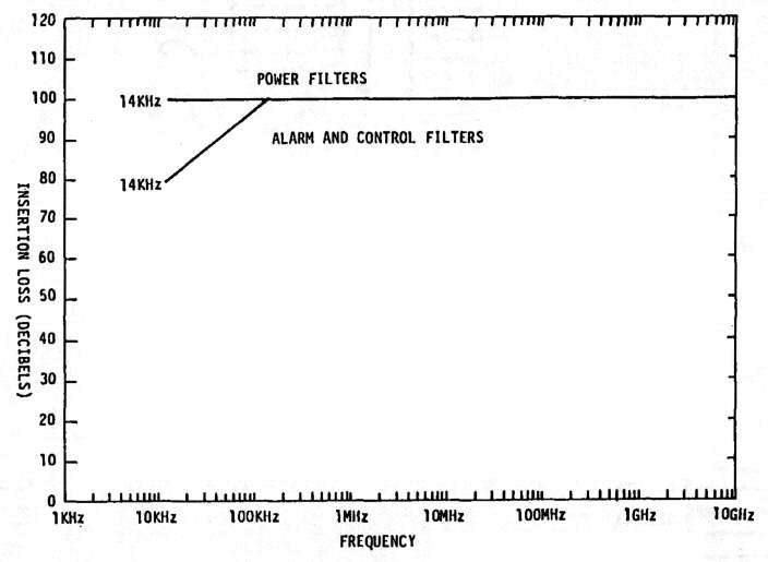
Figure 10
TEMPEST Required Filter Insertion Loss
2.8.1 EMI Filters for Electrical Power. Power filter performance requirements are typically stated in terms of dB insertion loss as a function of frequency as seen in Figure 10, as measured In accordance with MIL-STD-220A, Method of Insertion-Loss Measurement. Power filters are generally of the passive type, consisting of resonant combinations of inductors and capacitors. They are available with both inductor and capacitor inputs. Those with capacitor inputs usually include a low inductance type feedthrough capacitor, followed by capacitor-inductor pi networks. The contribution of the inductors is critical in the low frequency end of the stop band (from 14 to a few hundred kilohertz). When inductor cores saturate as a result of load currents, the insertion loss curve tends to shift to a higher frequency, increasing the cutoff frequency (the frequency where the insertion loss has reached 3.01 dB) and the range of pass-band frequencies. At frequencies above a few hundred kilohertz, the turn-to-turn capacitance of the inductor winding tends to limit its contribution and the capacitor performance is more critical. The series inductance provided by the connecting leads of the capacitors tends to limit.their higher frequency performance (a few MHz and higher), and here the feedthrough capacitors contribution become critical. Feedthrough capacitors of the size usually employed in power filter applications typically have a self parallel resonance with winding inductance ranging from a few hundred kilohertz to a few megahertz. Some manufacturers overcome this resonance defect by staggering sizes of feedthrough capacitors, or by adding low inductance capacitors In parallel. When not corrected for, this resonance results in a sharp dip in the stop-band insertion loss curve at the resonant frequency to values below the typically required 100 dB. These resonant defects are not usually identified in MIL-STD-220A test results because tests are run typically at a few discrete frequencies covering the required range of performance. The defects are normally identified when tests are monitored or supervised by knowledgeable government representatives looking specifically for them. The insertion loss performance of the power filter above 20 MHz is measured under no-load conditions in a matched 50 ohm coaxial measurement system. For the filter performance at the high end of the frequency spectrum (1 to 10 GHz) the feedthrough capacitor and filter-can performance as a vaveguide below cutoff attenuator is critical.
Power filters for 400 Ez applications typically require power factor correction coils to compensate for the large capacitors contained in the filters. When not provided, the current demand by the filter may be excessive, and the filters are usually acoustically noisy. These correction coils are not normally supplied by the filter manufacturer unless they are required in the specifications.
2.8.2 EMI Filters for Signal Circuits. Digital type signal circuits
utilize square-vave type pulses as observed in the time domain. The fast
rise and fall of the square-wave signal leading and trailing edges, tends
to make passive, inductor/capacitor (L/C) filters ring at frequencies close
to the cutoff frequency in their pass band where L/C combinations in the
filter result in a gain rather than a loss in attenuation. The best performance
for digital circuit filters occurs when the filter source and load impedances
match the driving source and load impedances, respectively, and when the
filter pass band is tailored to the baud rate of the signal circuit. TEMPEST
recommended filter attenuation curves are shown in Figure 11, with curve
A applicable up to a baud rate of 1,000 baud pulses per becond (B.P.S.).
Curve B is used to 3,000 B.P.S., curve C to 10,000 and curve D to 30,000
B.P.S. When properly designed, the useable baud rate can approach 1/3 of
the filter cutoff frequency (3.01 dB insertion-loss). The curves in Figure
11 show attenuation in dB as a function of frequency and they are measured
differently than the insertion loss curves of Figure 10, which are measured
to MIL-STD-220A specifications. For filter attenuation as shown in Figure
11, the filter is inserted in a measurement circuit with source impedance
matched to the filter input impedance, and load impedance matched to the
filter output impedance. A measurement signal Si, induced at the filter
input is compared to the signal So remaining at the filter output,
with the ratio 20 log Si/So providing the attenuation in dB. If the circuit
source and load impedances where the filter is installed, are substantially
mismatched to the filter, the ringing of the filter is increased drastically,
and the acceptable stop band curves of Figure 11 will be altered significantly.
As a result of these critical factors in the signal circuit filter design,
it is best to let the government either furnish the signal filter for contractor
installation, or provide well defined impedance parameters for specifying
required filter attenuation performance with frequency. For audio or tone
type signal circuits, the filter curve as shown In Figure 11, must have a
cutoff frequency which exceeds the highest signal frequency so that the signal
distortion does not occur at the higher signal frequencies.
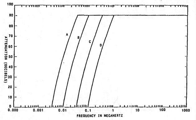
Figure 11
TEMPEST Signal Filter Attentuation Requirements,
Measure With Matched Source and Load Impedances
2.8.3 Electrical Filter Design Specification Requirements. General electrical filter specification MIL-F-15733E, Filter, Radio Interference, General Specification for, governs critical design features for all required electrical filters such as range of operating temperatures, impregnant flash point, terminal size and strength, dielectric withstand voltage, voltage drop, insulation resistance, filter sealing means, overload, impregnant, finish, moisture resistance and filter marking. NAVFAC Guide Specification NFGS 16650, Radio Frequency Filters for 60 Hertz Power Lines contains recommendations for the fabrication, testing and installation of EMI filters, and should be utilized in preparing specifications. It includes a beat rise limit of 20º C, full rated current load, in a free space environment, or 40º, when filters are mounted in a modified NEMA Type I enclosure. It requires insertion loss tests at 10, 50 and 100 percent of load with the use of modified buffer networks to extend the lower test frequency to 14 kHz. It limits dc voltage drop to less than 0.5 V at full rated current, and ac voltage drop to 1 percent of rated line voltage. It limits filter impregnant flash point to greater than 165º C. It requires bleeder resistors to drain filter capacitor stored charge in accordance with, NFPA 70, National Electric Code, Article 460-6 requirements. Significantly, it calls for submission of certificates of conformance or compliance of equipment and materials before their delivery. Where customer requirements include power filters for larger than 200 amps rated load, and/or greater than 100 dB measured insertion loss, it may be advantageous to specify parallel combinations of filters rated at 200 amps or less, or series combinations of filters rated at griater than 60 dB insertion loss each. Where feasible, power systems should be designed so that individual filter rated loads do not exceed 100 amps, the MIL-STD-220A type,testing limit of most filter manufacturers.
2.9.4 Insertion Loss Measurements of Electrical Filters. The available test specification for the measurement of electrical filter insertion loss is MIL-STD-220A. The test methods in this standard are intended to provide data for quality control during quantity production of power line filters. The test conditions specified with 50 ohm input and output terminations are satisfactory for this control purpose, but do not represent conditions that exist in actual circuits or installations. The power source impedances in actual installations are typically much lower than 50 ohms at frequencies in the filter pass band, and up to, 14 kHz where the filter is required to provide greater than 100 or 120 dB of insertion loss. The power filter load impedances at actual installations also vary widely, depending on equipment loading, are not constant as a function of frequency, typically have a leading power factor, and are often nonlinear. Currently, methods used for in situ measurement of power filter attenuation using current injection and measurement probes are being developed by the Naval Civil Engineering Laboratory, Port Hueneme, California. Some test results to date show the power filters providing 20 to 30 dB less attenuation from 14 kHz to several MHz than the greater than 100 dB of insertion loss required by NSA 65-6, (Figure 10), as expected. In specifying filter performance tests, the use of extended buffer networks to allow for insertion loss measurements to a lower frequency limit of 14 kHz should be required. The buffer network assembly consists of a series inductor, and feedthrough capacitor. Two of these networks isolate the load-current source from the receiver and output meter so that greater isolation at the test frequencies is provided thiough the networks than through the filter under test. The original MIL-STD-220A test specification called for a lowest frequency measurement of 100 kHz and a maximum current loading of 100 amps. The extended buffer network provides additional isolation to a lower frequency of 14 kHz. In order to measure the rated load-currents higher than 100 amps, buffer network inductors with higher current handling capability must be provided in the test circuit. The use of dc to load the filter during insertion-loss testing is not a representative loading on filters designed for use with ac power circuits, since the de permeability of the filter-inductor cores is different than for ac. The use of ac current loading of ac power filters during insertion-loss testing should be encouraged. Where the normal buffer networks at higher current ratings are not available, it is feasible to use an additional power filter that is identical to the one under test in place of the two buffer networks. The additional filter is installed in the wall of a shielded test chamber, beside the filter under test, and is connected in series with the test filter and either an ac or a dc current source. A low voltage ac current source can be used to drive the two series-connected filters in a short circuit load arrangement, with the peak load current controlled by the current source (typically a transformer with adjustable taps). The filter-out, direct reference signal is fed through the shielded test chamber wall by means of a bulkhead adaptor, including series blocking capacitors provided to protect the source and receiver from the current source during the filter-in measurement. The filter-in signal is next fed through the filter under test and measured for comparison to the reference signal. The isolation provided by the additional filter in series with the impedance of the current source and the inductance provided by the connecting cables will normally be sufficient to result in a meaningful filter measurement test.
2.9 Facility Grounding System. The facility ground system is typically composed of four subsystems as described in MIL-HDBK-419; the earth electrode subsystem, the lightning protection subsystem, the electrical fault subsystem, and the signal.reference subsystem. The earth electrode subsystem Is the grouping of driven rods, buried mesh grids, or buried radial conductors utilized to provide a low resistance to earth (less than 10 ohms) for attachment by the lightning subsystem, the fault protection subsystem, and the signal reference subsystem. In areas where high earth resistivity makes it difficult to achieve less than ten ohms with a reasonably sized buried earth electrode system, it may be necessary to add chemical treatment in the form of ion-producing salts such as magnesium sulphate, copper-sulphate or calcium chloride to the soil surrounding the buried electrodes or conductors. Such treatments can be very effective in reducing resistance of values of the electrode systems, but they must be provided with a replenishment schedule to overcome the leaching effects of groundwater runoff.
2.9.1 Lightning Protection subsystem. Lightning protection grounding includes roof mounted air terminals with attached down conductors to the earth electrode system. Location and height of air terminals necessary to provide adequate zones of protection is treated extensively in NFPA 78, Lightning Protection Code, and MIL-HDBK-419 and they vary considerably with the size and slope of the roof structure, height of the building or the height of protrusions extending above the roof level. Air terminals are composed typically of either suspended horizontal conductors a minimum of 6 ft above the highest projection, vertical masts with a 450 cone of protection for important buildings, or a connected system of vertical metal (copper, aluminum or bronze) rods up to 3 ft in length, with a spacing of less than 50 ft (on flat roofs), and connected to the grounding system with a minimum of two down conductors.
2.9.2 Fault Protection Subsystem. Fault protection requires the grounding of all exposed metallic equipment frames which contain electrical power wiring to the earth electrode grounding system so that any faulting of energized conductors to frame will result in a low impedance ground return path for positive actuation of fusing and breaker systems. A green wire ground system of wiring for electrical circuits is required, and metal conduits may not be relied upon for the ground return conductor. The ac neutral is normally grounded at the service transformer and at the first disconnect means, in compliance with MIL-STD-188-124, Grounding, Bonding and Shielding for Common Long Haul/Tactical Communications Systems, General Requirements. Conduits, boxes, all of the metallic piping, tubes, and their supports should be electrically continuous and bonded to the facility ground system, along with the metal structures they are attached to. A shielded enclosure with a single point ground, needs to be solidly grounded to the same facility ground system as the power system and the facility structural members. The single point ground stud is best located close to the power filter penetrations. For isolated shielded enclosures, typical for TEMPEST requirements, there is no green wire ground or conduit grounding of the enclosure, and the neutral is normally provided a power filter with the same attenuation requirements as for the energized phases. Without solid grounding to the facility ground system dangerous differences of potential could exist between the enclosure and facility structural members, contributed in part by the capacitive reactive currents of the power filters. Fault clearance and breaker action also, requires this solid single point grounding for proper functioning.
2.9.3 Signal Reference Ground Subsystem. The signal reference subsystem
can be divided into two subclasses, one for higher frequencies (above 300
kHz) and one for lower frequency signal networks. The higher frequency grounding
is composed of three primary components, an equipotential plane, equipment
grounding conductors, and structural steel elements, electrical supporting.
structures and utility piping, with all of the foregoing connected to the
earth electrode subsystem. When these three components are contained with
a metal shielded enclosure with a single point ground system, they all come
together at the single point ground stud. The higher frequency ground system
is comprised of a multipoint equipotential plane to provide a minimum grounding
impedance (short ground lead connection) for equipment cabinets. Equipment
chassis are then connected to the cabinets and signal return leads are connected
to the equipment chassis. The connection of the equipotential plane to the
earth electrode subsystem is made to assure personnel safety and to provide
a low impedance path for the lower frequency signals. Within a shielded enclosure
the floor of the metal enclosure can be utilized as an equipotential ground
plane for the higher frequency grounding. When a raised access flooring system
is installed in the shielded enclosure, it may more . conveniently be utilized
for the multipoint grounding connections. It should be constructed with
conductive stringers and panels conforming to MIL-F-29046(TD), Flooring,
Raised, maximum resistance requirements. This raised flooring system
should be grounded at intervals, (10 ft or less) around its periphery to
the parent shielding material utilizing a welded connection to the wall shielding
in a welded enclosure or bolted to seam bolts (with the bolts replaced with
a threaded rod with nuts and washers) in a bolted enclosure, as shown in
Figure 12. Equipment cabinets can then be conveniently connected to stringers
with short grounding leads.
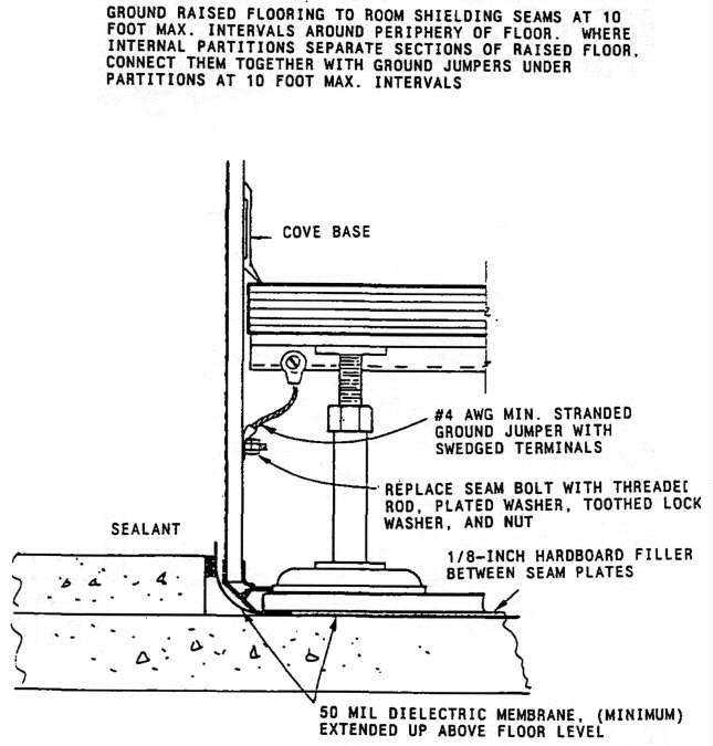
Figure 12
High Frequency Grounding, Using Raised
Flooring as an Equipotential Plane
The low frequency grounding system approach references the signal circuits
to a single-point ground which is then connected to the facility ground,
or to its own buried ground electrode system. Ideally, a separate conductor
would be extended from the single-point ground to the return side of each
of the numerous circuits located throughout a facility. This would require
an extremely large number of conductors, and so a compromise approach uses
a ground bus network in the form of a tree. This system is described in
MIL-HDBK-419, and consists of feeder ground cables attached to branch ground
plates, isolated from the structure and metal conduit system an stand-off
insulators., The branch ground cables, No. 2 AWG minimum, attach to the trunk
ground cable, 1/0 AWG minimum, which is then attached to the main ground
plate, which is also isolated electrically from the structure. The main ground
plate is then connected to the earth electrode subsystem ground by means
of a ground cable with a minimum size of 500 cmil for each foot of required
length and limited to less than 200 ft length if possible. Within a metal
shielded enclosure the single-point ground stud or plate is usually placed
in the wall of the shielded enclosure and serves the function of the main
ground plate for TEMEST low frequency ground networks. It is then connected
from the exterior of the shielded enclosure to the earth electrode subsystem
ground. See Figure 13 for a low frequency ground system in a shielded enclosure
and Figure 14 for a single point ground stud installation in a bolted enclosure.
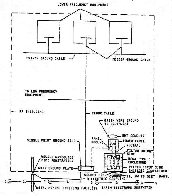
Figure 13
Low Frequency and Power Grounding Within a Shielded Enclosure
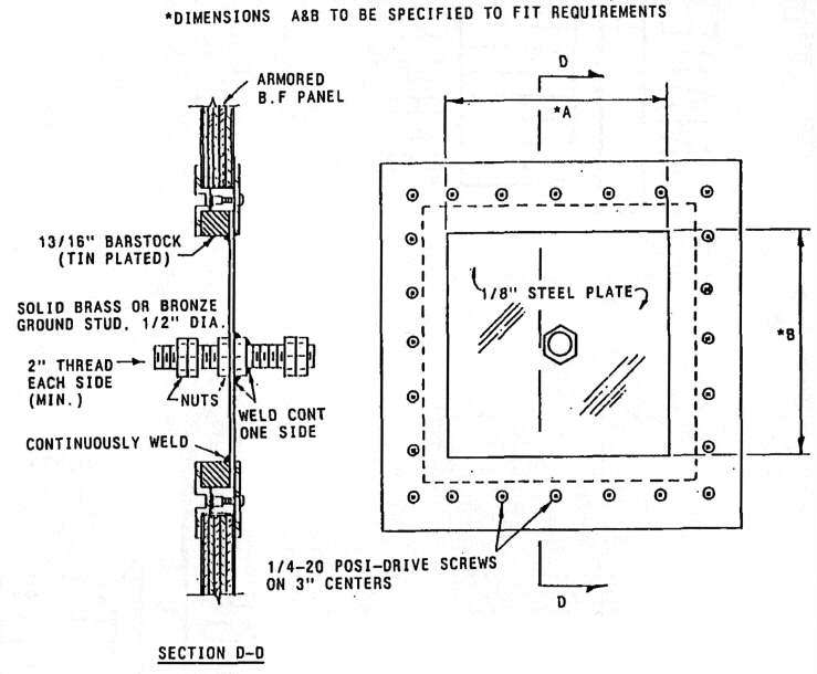
Figure 14
Single Entry Ground Stud Penetration in a Bolted Plate Assembly
2.10 TEMPEST Shielding Requirements. Facilities which contain electronic
equipment which process classified information must be shielded in accordance
with OPNAVINST C5510.93D, Navy Implementation of National Policy of Control
of Compromising Emanations. This type of electromagnetic shielding is
known as TEMPEST shielding and is required to reduce the conducted and radiated
emissions from within the sensitive environment to an undetectable level
outside the shielded enclosure in uncontrolled areas. The typical required
level of shielding effectiveness (SE) is 100 dB to an upper frequency of
10 GHz, measured in accordance with NSA 65-6 procedures, and Figure 15 in
this manual. Special requirements for the TEMPEST shielded enclosures can
include electrical isolation on all six sides (greater than some specified
minimum dc resistance ranging from 1,000 ohms to 15,000 ohms or greater).
It includes single-point grounding of the shielding to the facility ground
system, electrical filters on all conductors penetrating the shielding (including
all power, phases and neutral, signal, telephone, alarm control and sensing).
It includes waveguide attenuator penetrations,for all piping penetrations,
seen typically in Figure 3, air vents (intake and exhaust) seen in Figure
2, and with inserts in piping that exceeds 1/2-in. (12.7 mm) I.D. (to provide
waveguide attenuation for frequencies to 10 GHz), as seen in Figures 5 and
6. The requirement for electrical isolation of piping, conduits and air handling
system ducting connections to the external sides of the enclosure of 6 in.
(152.3 mm) of isolation within 2 in. of the shielding surface.
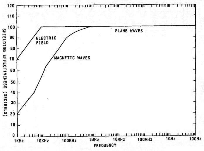
Figure 15
TEMPEST Required Shielding Effectiveness
2.11 Types of Shielding Systems. There are large varieties of construction techniques and materials utilized for EMI shielded enclosures. The basic shielding material and its thickness are generally selected based on the low magnetic frequency shielding requirements. Shielding effectiveness measured with low frequency magnetic fields is provided mainly by absorption rather than reflection losses. This is because the magnetic field wave impedance is low compared to electric and plane wave field impedances, and it is the mismatch in impedance between the metal surface (which is very low), and the wave impedance which results in the reflection loss. The absorption loss is directly proportional to the thickness of the material and to the ft2 of the permeability. The permeability of sheet steel at low frequencies is over 200 compared to a value of one for copper, aluminum, and other nonmagnetic shielding materials. NSA 65-6 TEMPEST shielding requires 20 dB of magnetic shielding effectiveness at 1 kHz, increasing to 90 dB at 100 kHz, as seen in Figure 15. This could be provided by two 26 gauge steel sheets, galvanized and clad on 3/4-in. (19 mm) plywood or particle board with bolted 1/8-in. (3.2 mm) thick galvanized steel seam plates, available from numerous manufacturers as modular shielded rooms. At the plane wave frequency end of the spectrum, 1 to 10 GHz or higher, the methods used for seam closure construction become very important. In this region of the frequency spectrum, resonant half-wave lengths are of similar dimension as seam bolt spacings, and openings and gaps become efficient radiating antennas. Depending on the type of parent building construction, other than shielding requirements could dictate the required thickness of shielding material. This is typical in vault construction, where Defense Intelligence Agency (DIAM) 50-3, Physical Security Standards for Sensitive Compartmented Information Facilities, require steel plate with 1/4-in. (6.3 mm) minimum thickness where reinforced concrete walls are not included.
2.11.1 Bolted, Modular Shielded Enclosures. Bolted, modular , shielded enclosures degrade in seam and penetration closures with time, with the rate of degradation dependent on presence of moisture, vibration, thermal expansion and contraction, and on contamination by corrosive materials such as salt spray or industrial atmospheric pollutants. The bolted seams which compress plywood or particle board fillers can loosen with cycles of expansion and contraction which are caused by combinations of moisture and heat. The wood fibers can be crushed during moisture intrusion, and the seam closure is then loosened when the fibers dry out resulting in shielding leaks. In addition, oxidation of the metal to metal surface contact points in the seam closure results in a non-conductive film which causes an increase in contact resistance and a resultant loss of shielding effectiveness. The Army Corps of Engineering Research Laboratory technical report M-296, EMI/RFI Shielding Effectiveness Evaluation of Bolt-Together Rooms in Long-Term Aging, June 1981, determined that the SE will degrade by 15 to 20 dB in three years even under ideal laboratory conditions. With less than ideal environments the degradation is more severe, and a reduction of 40 dB in 6 months to a year would not be unusual, especially at door closure surfaces. Welded seams, and welded penetrations, when properly designed to allow for some flexibility and motion without cracking of welds, are far superior to the bolted and clamped closures.
2.11.2 Welded Shielded Enclosures. Welded steel enclosures are preferred for TEMPEST shielding because of their better seam closures, long term reliabilty and maintenance of the designed shielded effectiveness. Welded enclosures for TEMPEST shielding effectiveness requirements, seen in Figure 15, are typically constructed of steel plate, varying in thickness from 1/4-in. (6.3 mm) to 14 gauge, supported on a system of metal studs such as seen in Figures 16 and 17, or in Figures 18 through 22, where typical exterior wall, wall-floor, wall-ceiling, interior wall-floor, wall-ceiling sections are shown, and including a sliding pneumatic expanding door frame section seen in Figure 20. The 16 gauge steel studding and 3/16-in. (4.8 mm) tubular channel seen in these figures serves as both a structural framework, and as a backup strip for the continuous butt welding of the steel sheets to the framework. Steel sheets are first tack welded or plug welded to the framework during assembly by some contractors, and some utilize a fired steel pin which is later welded. The continuous welding of the steel sheets to the framework is then carefully sequenced to control warping and buckling of the steel plates. Sheets are overlapped for continuous welding, seen typically in Figures 23 through 25 when a backing strip or stud is not provided to back up the weld. The tubular framework is laid out ou 4 or 5 ft centers depending on the width of the steel sheets used, with intervening frame members as required, typically 2 to 4 ft on center. For TEMPEST shielded enclosures requiring electrical isolation from the parent structure grounding, a dielectric underlayment is used to isolate the sheet steel flooring from the underlying concrete slab. This is seen in Figures 7, 12, 20, 21, 22. The quality of electrical isolation materials used ranges from sheets of Masonite hardboard, to 56 mil PVC roof membrane, 1/8-in. (3.2 mm) polypropelene sheet, or 60 mil chlorinated polyethylene (CPE). The hardboard is the cheapest, and the poorest, since it cannot be sealed from sheet to sheet to form a moisture impervious membrane as the other materials mentioned can. Further, when it becomes wet with contaminated water it can lose its electrical isolation. The use of hardboard should be limited to its application as a filler material between bolted or welded seam plates and should not be relied upon for the necessary electrical isolation. The dielectric underlayment material should be overlapped and glued at seams to form a moisture barrier, and should extend up at flooring edges as seen in Figure 12, or around floor penetrations such as the column seen in Figure 7, or the anchor seen in Figure 26.
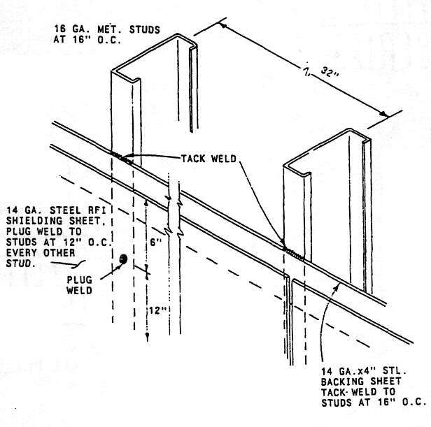
Figure 16
Welded RF Shielding of Wall Section
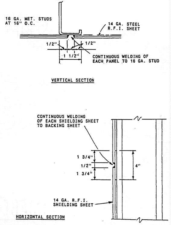
Figure 17
RF Wall Shielding, Seam Detail
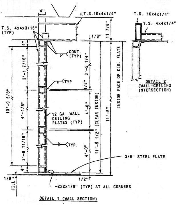
Figure 18
RF Shielding, Wall-ceiling Section
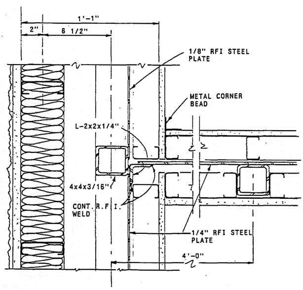
Figure 19
RF Shielding, Vault Ceiling to Interior Wall Section
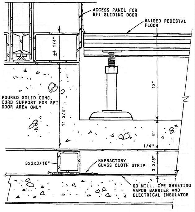
Figure 20
RF Shielding, Sliding Door Frame Section
Figure 21
RF Shielding, Interior Wall-floor Intersection
With Electrical Isolation Underlayment
Figure 22
RF Shielding, Interior Wall-floor Intersection on Tubular Frame
Figure 23
RF Shielding of Floor-wall Intersection With Overlap Seam
Figure 24
RF Shielding, Floor Layout
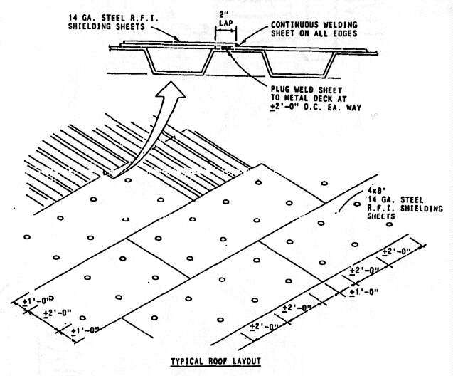
Figure 25
RF Shielding, Roof Layout With Metal Decking
2.11.2.1 Large Welded Structures. In extremely large welded structures, thermal expansion can result in significant displacement in the metal structure, especially during construction, before the shielding is protected from the external thermal environment. Expansion joints may be required in very large welded shielding structures for both vertical and horizontal expansion in the shielding walls. The attachment of metal sheets to fixed metal columns and beams should also allow for some flexibility, as well as transition thickness of metal between the typically thin shielding sheets and the heavy steel beam and column members, as seen in Figure 7. A refractory material must be provided to protect the dielectric underlayment during the welding of the seams. Examples of this are seen in Figures 20 through 22.
2.11.2.2 Warping Due to Welding. Warping or buckling of floor sheets
during the welding process is a serious problem in most welded room
installations. When concrete anchors or fired pins cannot be used to hold
the sheets against the underlaying concrete slab, typical of electrically
isolated TEMPEST enclosures, then a tubular framework as seen in Figures
20 and 22 can be utilized under the floor sheets. Some welded floors have
a concrete slab poured over them, and this can be made thick enough to accept
some floor warpage. A heavier steel sheet such as 3/8-in. (9.5 mm) plate
can be used for the floor, with a reduced buckling problem compared to floors
of thinner material. Heating of the floor sheets and quenching with water
spray is another means used to reduce warpage after it has occurred. Some
earthquake resistant designs require anchoring of the shielded floor to the
parent structure. With TEMPEST isolation requirements, normal concrete anchors
or pins may not be acceptable, and an isolated anchoring scheme is shown
in Figure 26.
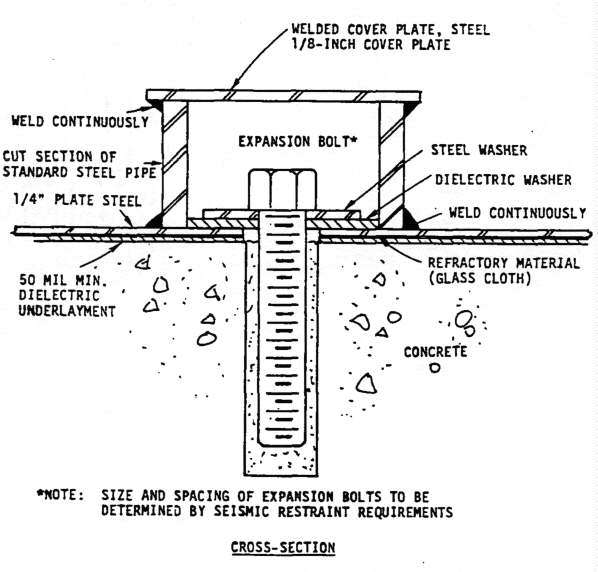
Figure 26
Anchoring of Steel Floor Plates With Electrical Isolation
2.12 EMI Conductive Gaskets, Cements and Tapes. The use of EMI gasket type materials in shielded enclosure construction is normally limited to penetrations, access hatch, and filter case closures. There is some use of conductive tapes under the seam junctures of bolted panel type construction or else bronze or stainless steel wool, covering the gap at the ends of adjacent seam plates. Additional materials include conductive cements and caulking materials, usually silver filled. Some cheaper varieties use tiny glass beads coated with silver, or copper flakes coated with silver. These conductive materials are usually utilized in penetrations, or as a retrofit fix at bolted seam leaks or bolted air vent leaks. A basic limitation to the gasket and tape materials is that metal to metal contact is made with the mating surfaces at high points without much surface pressure available (less than that under bolted seam plates to shielding). When surfaces in contact are new and bright, the contact resistance is low and shielding effectiveness measured is high. Oxidation and dissimilar metal-to-metal corrosion rapidly deteriorate the bonds and degrade shielding performance. The best long term shielding design uses no gasket, tape, or conductive cement materials, and has all penetrations continuously welded or brazed. The conductive cements and caulking materials are available in hard and brittle form when set-up, (this type provides the highest conductivity) or can be obtained in a pliable mix when set up. The brittle material cracks easily with motion of the mated parts where it is applied, to result in leakage. The pliable material allows for flexibility but provides minimal shielding. Another disadvantage to conductive cements is that they are expensive. Some tape materials are available with an advertised conductive adhesive backing. Some have small metal particles embedded in the adhesive that make contact between the metal tape and surfaces where applied. Others are embossed so that the metal tape makes contact through a raised ridge to the surfaces where applied. The use of metal tapes with conductive adhesives is a Band-Aid or temporary measure at best. There is insufficient metal-to-metal contact pressure available to inhibit moisture or retard oxidation of the metal-to-metal contact points for long periods of time, and their use should be limited to laboratory measurements or temporary applications.
2.12.1 Mesh Gaskets. The mesh gasket usually found under the clean compartment lid of power filters.does not degrade as fast as other gasket applications. The hot filter case, compared to the surrounding air, tends to inhibit moisture penetration into the gasket. When gaskets are required, they should be chosen first to provide the same coating material as the parent shielding where they are installed. Of the coatings that are available, tin plate seems to provide the best long term conductivity against typical shielding material firiishes. The mesh gasket materials are not typically resilient like beryllium-copper fingerstock used in door closures, and once compressed in a seam or penetration closure they can take a set. Subsequent cycles of opening and closing will then require greater pressure to break down surface oxidation. Brightening of contact surfaces and frequent replacement of gaskets are recommended in order to retain necessary shielding effectiveness.
2.13 Fingerstrips. Door closures with the exception of the pneumatic-expanding, sliding door, utilize combinations of rows of fingerstrips for achieving an electromagnetic seal between door leaf and frame surfaces. Fingerstrips are typically made from microprocessed beryllium copper, about 4 mil thickness, and with available plated finishes of such metals as gold, silver, rhodium, nickel, tin, zinc and chromium. The material provided in most shielding manufacturer's doors is uncoated beryllium copper, unless otherwise specified. If the door closure mating surfaces are brass or bronze, the beryllium copper finish is a good choice for galvanic compatibility. Against aluminum or zinc, tin plating would be preferred. The fingerstrips are available with an adhesive backing strip to allow for installation without soldering. Another type utilizes "pop rivets" for securing the strips, and some are soldered in place. When the door closing action causes both wiping and compression of the fingers, the oxides and foreign materials can be broken through and good metal-to-metal contact made. Many of the knife edge type closures do not provide sufficient compression and wiping to clean the contact surfaces, and periodic maintenance with chemical cleaners is required. Strips of exposed fingers require periodic replacement of broken or damaged strips.
3.1 Introduction. It is extremely important that the requirements for EMI shielding be identified during the Planning Phase of the project. The requirements must be identified to allow the EMI shielding to be integrated into the structure at the lowest possible cost while meeting the operational requirements of the sponsor and user. It is also important that the shielding cost be established as early as possible during the project development to ensure that adequate funding has been established to cover project cost and avoid delays in the facilities procurement process.
3.1.1 Construction Requirements. There are a number of requirements which dictate the construction of EMI shielded enclosures. These include: safety for personnel, ordnance and fuel (HERP, HERO AND HERF); protection of sensitive communication-electronic (C-E) equipment from ambient electromagnetic EM energy or the intense EM energy generated by the detonation of a nuclear device (EMP); preventing classified information (compromising emanation) from radiating or being conducted out of a controlled area (TEMPEST).
3.1.2 EMC Surveys and Studies. Any required electromagnetic compatibility (EMC) surveys and studies should be conducted during the planning Phase. The EMI shielding requirements are established in the BESEP which is prepared by the SPAWARSYSCOM at the request of the sponsor. The results of the efforts expended during the planning phase to completely and accurately define the EMI shielding requirements should not be underestimated. Defining the shielding requirements (attenuation versus frequency) for the project during the planning phase will minimize the possibility of costly changes during project design and construction phase. Not including well defined shielding requirements during the Facility Study could be costly in terms of money, time and shielding effectiveness; the project budget may be greatly exceeded, the completion of the facility may be delayed, the required shielding effectiveness may not be reached, or mo re often than not a combination of all of the above may occur.
3.2 Types of Shielded Enclosures. There are a number of programs, directives and instructions from various commands that require shielding to eliminate or reduce the electronic energy in a critical area. The TEMPEST program is of primary concern in this publication but the material presented is appropriate for other EMI enclosures.
3.2.1 TEMPEST. One of the moat critical shielding programs is the TEMPEST program. TEMPEST shielding may be required in facilities that house communication-electronics (C-E) equipment that process classified information. Facilities which contain this type of equipment must conform to the policies and regulations contained in OPNAVINST C5510.93, and to the appropriate National Security Agency COMSEC Publications. The shielding effectiveness (SE) requirements include both attenuation and frequency for the TEMPEST shield and should be contained in the BESEP. In the absence of defined frequency and shielding effectiveness limits in the BESEP, the cost estimate and construction techniques for the shield should provide for the shielding effectiveness defined in NSA 65-6, with the shielding effectiveness versus frequency as shown in Figure 15 and power filter insertion loss shown in Figure 10.
3.2.2 High Altitude Electromagnetic Pulse (HEMP). The detonation of one nuclear device at high altitude produces an extremely intense electromagnetic pulse (EMP) that can illuminate surfaces of a large geographical area without the other effects of nuclear detonation being present (blast, thermal shock and nuclear radiation). Unless HEMP protective measures are provided, much of the nations sophisticated electronic communications systems may be rendered useless. The primary effect of HEMP is the production of large transient voltages and currents in conductors such as power and telephone lines and electronic equipment cabling. The criteria for facility HEMP protection is covered in NAVFAC Design Manual DM-12.02.
3.2.3 Hazards of Electromagnetic Radiation to Personnel (HERP). Electromagnetic radiation, especially in the microwave frequency region, can be extremely damaging when absorbed by the body. The electromagnetic radiation can also induce voltage between metal structures and earth. These induced voltages may cause shock or RF burns to personnel. These threats can be considerably reduced by EMT shielding, proper bonding, and grounding of metallic structures. NAVELEX 0101,106, Electromagnetic Compatibility and Electromagnetic Radiation Hazards, contains technical information on Radiation Hazard (RADHAZ).
3.2.4 Hazards of Electromagnetic Radiation to Ordnance (HERO). Electromagnetic radiation, under certain conditions, can detonate electro-explosive devices (EED) contained in ordnance material. The maximum allowable electromagnetic field intensity for various classifications of ordnance is defined in NAVSEA OP-3565/NAVAIR 16-1-529, Electromagnetic Radiation Hazards.
3.2.5 Hazards of Electromagnetic Radiation to Fuel (HERF). Electrical arcs or sparks caused by electromagnetic radiation induced voltages create a potential hazard at locations where fuel vapors may be present. The ability of an arc to ignite a vapor-air mixture depends upon the susceptibility of the fuels to ignition, the presence of a flammable fuel-air mixture, the energy contained in and the length and duration of the arc. National Fire Protection Association (NFPA) Standard No. 401, Aircraft Fuel Servicing, Standard for, and NAVELEX 0101,166, Electromagnetic Compatibility and Electromagnetic Radiation Hazards, contains information on the potential hazards to fuels.
3.2.6 Shielding for Communication-Electronics (C-E) Facilities. When a facility is to contain sensitive C-E equipment and there are no regulations mandating EMI control of the surrounding environment, it may be necessary to include shielding in the structure to protect the C-E equipment from the external ambient EMI. This type of facility EMC shielding may be necessary to protect equipment such as computers from malfunction or damage. The level of shielding effectiveness required and the frequency range of the required shielding must be calculated, based on the background EM ambient and equipment susceptibility surveys obtained from the EMC evaluation. These surveys are provided by the SPAWARSYSCOM at the request of the sponsor.
3.3 Electromagnetic Compatibility (EMC) Evaluation. An electromagnetic compatibility (EMC) evaluation should be conducted during the planning phase. The EMC evaluation should identify environmental electromagnetic Interference from all measurable or known sources in vicinity of the site location. This part of the evaluation is the responsibility of SPAWARSYSCOM but is usually performed at the request of the sponsor. An equipment study should also be conducted to determine the radiated and conducted emission levels and the radiation and conducted susceptibility levels of the equipment proposed for installation in the site. This portion of the evaluation is the responsibility of the sponsor and occasionally involves access to classified information (frequency ranges, field strengths, pulse widths and rise times). This information is usually available only to the user. The results of these investigations shall be used to calculate the required radiated shielding effectiveness and the required conducted attenuation. All pertinent information should be set forth in the BESEP.
3.4 Base Electronic System Engineering Plan (BESEP). The basic document used by SPAWARSYSCOM for planning shore electronic facilities is the BESEP. It translates the operational requirements into a detailed technical plan to meet the general requirements. In addition to general requirements, equipment and facility layout and type of construction, the BESEP must clearly define any special electrical requirements, security requirements, the EMC evaluation and the electromagnetic (EM) shielding required. The.BESEP is prepared'by SPAWARSYSCOM and with the assistance of NAVFAC if requested. It is the responsibility of the sponsor to request that SPAWARSYSCOM prepare the BESEP and ensure that the EMI shielding requirements and cost are included in the Facility Study (DD 1391).
3.5 Construction for EMI Shielding. The material and type of construction should be determined during.the planning phase. Various highly conductive materials are available as the shielding material; these include copper, aluminum or steel. The shielding effectiveness required to meet the TEMPEST criteria can generally be constructed cost effectively with steel sheets. The thickness of the material is usually not the most critical part of the shield. Two layers of 26 gauge galvanized steel will generally provide sufficient SE. The most critical part of the EMI shielding is its discontinuities, such as penetrations, methods used to join the sheets into a complete enclosure and the door closing and sealing means provided. The two primary methods of construction of shielded enclosures are demountable (bolted) and welded. For small size enclosures the bolted types are usually less expensive. When the enclosure is large enough to require numerous structural member penetrations, the welded type, which provides superior long term shieldirig effectiveness, may become cost effective.
3.5.1 Demountable Enclosures. Demountable enclosures are constructed with modular panels and seam plates with standard 4 ft wide panels available in 8, 10, or 12 ft standard lengths from several manufacturers. The panels consist of 3/4-in. plywood or particle board laminated between two zinc coated 24 or 26 gauge steel sheets. The panels are connected together with a framing and joining system that provides both support for the self-standing enclosure and clamps the panels together with a fairly constant seam pressure that provides a uniform electrical continuity between the panels. The joining clamps are usually fastened together with 1/4-20 screws on 3 or 4-in. centers, torqued to about 80-in. pounds. The screws are typically provided with blind nuts so that the screw does not result in a full penetration of the shielding which could deteriorate with oxidation to result in an antenna extending on both sides of the shield.
The bolted type of the shielded construction provides good initial shielding effectiveness when mating surfaces are clean and bright to result in low resistance in seam closures and joints. With proper tensioning and torqueing of bolts and penetrations, this type of shielding construction is usually able to provide the required 100 dB performance required by NSA 65-6, National Security Agency Specification for RF Shielded Enclosures for Communications Equipment: General Specification.
However, in a bolted-seam closure, the metal to metal contact occurs on high points (an a microscopic basis). With time, these points can oxidize, especially when the seams are not sealed to prevent exchange of air, and there is a resultant degradation in shielding performance. The use of RF mesh gasket materials under seam or penetration closures normally results in faster degradation than the seam closures, and their use should be prohibited in the specifications. Two types of bolted penetration panels which provide for welded or brazed piping or conduit penetration treatment are shown in Figures 3 and 4. This same type of bolted penetration panels should be used for the single entry ground.stud penetration, seen in Figure 14.
3.5.2 Welded Enclosures. This type of construction is usually employed with TEMPEST shielding requirements. For small vaults a 1/4-in. steel plate satisfies Defense Intelligence Agency (DIAM) 50-3, Physical Security Standards jor Sensitive Compartmented Information Facilities, and often is combined with a larger bolted enclosure. For enclosures larger than about 1,000 ft2 the welded enclosure looks more cost effective, and can be free standing, isolated on all six sides with dielectric underlayment and structural hangers, or can be integrated.into the building beam and column structures. Where the BESEP dictates electrical isolation and single-point ground for TEMPEST requirements the welded enclosure should of the free standing design with penetrating columns enclosed in shielding as seen in Figure 8 and with a tubular steel backing for all six sides of sheet steel (typically 14 gauge or thicker), The tubular steel framework is typically laid out on a 4 by 4 ft grid, or 2 by 4 ft, corresponding to 4 by 8 ft sheets of steel, to control warping and buckling of the welded steel sheets, and to provide structural rigidity for wall and ceiling. Tubular frame members are typically 3 by 3 or 4 by 4 in., 1/8-in. thick steel. The sheet steel seams should be continuously welded using MIC welding to prevent voids, gas pockets and incomplete fusion, and to avoid electrical discontinuities in the seams. All welds should be backed up with steel, either with overlapping of the sheets, welding against a tubular frame member, or against a backing strip of equal thickness to the sheets, in order to minimize possible electromagnetic leaks. Examples of seam configurations, column and beam junctures, floor-wall intersections, column tops and bases, are seen in Figures 7 through 9 and Figures 16 through 25 for both welded and bolted construction. Examples of several types of bolted and welded seam and door closures are seen in Figure 1. Floor drain and wall penetrations with a waveguide insert attenuator disc are seen in Figures 3, 5 and 6.
4.1 Introduction. When NAVFAC authorization is received by the Engineering Field Division (EFD) for the design of a project requiring Electromagnetic Interference (EMI) shielding, the Project Manager (PM) and the Engineer-In-Charge/Architect-In-Charge (EIC/AIC) shall review the Facility Study and BESEP to ensure that the shielding requirements are included. A copy of the BESEP should be reviewed by the EFD's Design Branch with expertise in EMI shielding to assure that the EMI shielding requirements are free from ambiguities including the area (or areas) to be shielded, the type of shielding required (Electromagnetic Compatibility (EMC), TEMPEST, High Altitude Electromagnetic Pulse (HEMP), Hazards of Electromagnetic Radiation to Personnel (HERP), Hazards of Electromagnetic Radiation to Ordnance (HERO), or Hazards of Electromagnetic Radiation to Fuel (HERF)), whether both radiated and conducted isolation is required, the decibels of attenuation required, and the frequency range over which the shielding must cover. All comments or questions on the BESEP should be sent the Naval Electronic Systems Engineering Center (NAVELEXCEN) that prepared the BESEP. Also, the PM or EIC/AIC should contact the Station to determine if any modifications to the BESEP are required. The Synopsis and Scope of Work should reflect the need for EMI shielding design expertise. The design team must have an EMI shielding specialist with in-depth knowledge of design and construction of shielded enclosures, and of shielding criteria including EMC and TEMPEST.
4.2 Predesign. Prior to negotiation of the design fee for the project it is recommended that a predesign conference be held to discuss the project requirements Including the EMI shielding system. At the conference the shielding requirements shall be presented including all special TEMPEST requirements. The advantages and disadvantages of the various types of EMI shielded enclosures shall be investigated so that a shielding system compatible with the needs of the users is provided. The Station's requirements for longevity, relocatability, maintainability and the possibility for a change in the basic shielding requirements must be investigated and detemined.
4.3 Architectural Design. Various architectural design considerations require special attention in an EMI shielded facility including EMI shielded doors, coatings, finishes and fasteners. EMI shielded doors are recognized as the "weak link" in the overall shielding system. Shielded doors come in various configurations, single doors, double doors, standard or custom sizes, but the number and size should be minimized. Neither the shielded enclosure nor the doors should be exposed to the outside environment, both are vulnerable to adverse environmental conditions and the shielding effectiveness rapidly deteriorates if exposed to the outside environment. If the shielded enclosure must open to the exterior, a weatherproof vestibule should be built between the enclosure and the exterior. Doors that are used continuously should be single doors. Double doors or larger openings should be used only for equipment access since the shielding effectiveness of double doors is difficult to maintain when the doors are in continuous use.
4.3.1 Comparison of Various Seals. To provide an EMI/RFI seal around enclosure doors requires a good and continuous electrical contact between the door and the door jamb. The seal can be made with RFI mesh gasket, fingerstrips usually of beryllium copper, or magnetic strips under a brass shimstock cover. Mesh gaskets take a set, are not self-cleaning or resilient, and oxidize or otherwise corrode to degrade the electrical conductivity at surface contact points. Therefore, mesh gaskets are not recommended. Fingerstrips are preferred over gasketing because fingerstrips are typically self-cleaning from the compression and wiping cycle in opening and closing the door or hatch. Sufficient compression of the fingerstrips is required to maintain a low resistance metal-to-metal contact from the door leaf to the frame when the door is cycled closed. The knife edge type seal is also available and uses beryllium copper fingerstrip in a door jamb recess. The knife edge type door seal is less susceptible to damage than the compression/wipe seal during normal operation but doesn't provide the compression that the compression/wipe seal does. The magnetic type of seal is less susceptible to damage during normal use than the seals using finjerstrips, but the magnetic-type has significantly lower shielding effectiveness.
4.3.2 Vestibule/Threshold Protection. An electromagnetically shielded vestibule is often required for the main personnel entrance to a TEMPEST enclosure, with either interlocked or alarmed sets of doors so that the shielded effectiveness is not violated when entering or exiting the enclosure. Emergency exit or equipment doors, without vestibules, can be provided and are normally designed to be opened only from the inside of the enclosure. The thresholds on standard RF doors are raised and can limit access. If the enclosure must be handicap accessible the threshold of the RF door must be specially designed. All accessories, such as cypher locks, doors, vestibules, door interlocking systems, combination locks, slide bars, and emergency hardware should be provided by the shielding manufacturers.
4.3.3 Size and Location of Power Filters. When laying out the space required for the enclosure, the architectural designer should carefully consider the size and location of the electrical power and communication filters. Power filters require adequate space, structural support and ventilation for heat dissipation. Also, the filters should be mounted on the shielded enclosure walls or as close to the enclosure as possible and should be accessible after installation.
4.3.4 Shielding of Access Penetrations. The architectural designer must also include raised-access flooring and dropped ceiling into the enclosure, if required, and ensure that there is adequate space above the ceiling and below the flooring to install electrical and mechanical equipment. He is also responsible for the design and specification of all coatings, finishes and materials which may contact or penetrate the EMI shielding system so as not to degrade the shielding system. It is recommended that the architectural drawings include an EMI penetration schedule listing all electrical, mechanical, civil, and structural penetrations of the shielding surface by type and location with reference to the applicable disciplines drawings for the actual penetration detail. This penetration schedule will be very valuable to the ROICC for testing purposes during the construction.
4.4 Structural Design. Structural design considerations for EMI shielded enclosures include welding details, support of the shielding system, and electrical isolation of TEMPEST shielded enclosures from the building framing members and foundation. The structural designer shall detail any special design features or welding requirements necessary to prevent warpage of steel panels. Where a modular, bolted enclosure is utilized, then bolt spacings and torque requirements shall be included. Seismic restraint and expansion joint design shall also be provided when required. Special precautions may be required to provide electrical isolation between a TEMPEST EMI shielded enclosure and all structural steel and the building foundation and framing so that the single point grounding criteria will not be violated. When the TEMPEST isolated enclosure is required to have seismic restraint, the anchoring means between the shielding and the structure must maintain the electrical isolation as shown in Figure 26. For specific guidance an TEMPEST isolations, see Figures 4, 5, 7, 8, 13, 21, 22 and 23.
4.5 Mechanical Design. EMI shielded enclosures require ventilation or air conditioning depending on the enclosure heat load. To maintain the required shielding, the mechanical design must provide waveguide below cutoff vents in all supply, return, and exhaust HVAC ducting which penetrates the shield. The vents are generally a honeycomb type arrangement of the proper geometry and material to provide the same SE as the basic shielding material without adversely affecting the air flow rate. The static pressure drop created by these vents, must be included in the HVAC calculations and the duct air velocity must be kept low enough to minimize the acoustical level. The air velocity should be kept below 1000 fpm. The vent's framework must be attached to the shielded enclosure using a method that provides a good and continuous electrical connection. The recommended method to attach the vent to the shield is to continuously weld the vent framework to the shield using MIG welding method.
4.5.1 Minimizing and Shielding Mechanical Penetration. The number of mechanical penetrations, such as piping, vents and drain penetration, should be minimized. The larger pipes, vents or drains may require waveguides below cutoff inserts to maintain the required shielding effectiveness. All penetrations should be continuously welded to the enclosure at the point of penetration. To facilitate welding pipes, vents, drains or air filters to the enclosure it may be necessary to weld a sheet of larger gauge metal to the shielding panels at the point of penetration. To minimize areas of potential RF leakage, penetrations to the shield should be localized to one area, as much as possible. All required penetrations must be clearly identified and detailed on the plans.
4.5.1.1 Dimensions and Materials for Shielding Mechanical Penetrations. TEMPEST shielding requires electrical isolations of all pipes, vents, drains and ducts within two 2 in. of the shield an the outside of the enclosure. The electrical isolation can be provided by inserting a section of nonconductive material with a minimum length of 6 in. in each pipe, vent, drain or duct that enters or exits the enclosure.
4.6 Fire Protection Design. Fire protection design considerations in EMI shielded enclosures include electrical filters for all conductors, special penetration details for all pipe penetrations for the fire protection system, and adequate emergency exits. All conductors that penetrate the shielded enclosure must be filtered. Pipe penetration required for the fire sprinkler system should be design similar to the penetrations required for the mechanical system. Larger than 1/2-in. diameter piping may require waveguide attenuation filter inserts to provide 100 dB attenuation at 10 GHz. The number of required penetrations, electrical and mechanical, should be minimized (refer to pars. 4.5.1.1).
4.7 Electrical Design Considerations. Important electrical design considerations should Include the electromagnetic continuity of the EMI shielding system, filtering of conductors, and grounding of the electronic equipment and EMI shield. A shielding specialist familiar with electrical conductivity and permeability must provide guidance for the overall shielding design by establishing required methods of penetration connections, seam connections, door connections, and surface preparations to eliminate all discontinuities of conductivity and permeability throughout the system.
4.7.1 Design Allocations for Filters. The electrical designer is responsible for providing filters on all power, signal, and communication cables which penetrate the shielded enclosure. All filters should be located close to the shielded enclosure. The ideal location for the filter units is on the surface of the shielded enclosure which should be shown on the plans. The number of power filter units should be minimized but multiple filter units may be required if the amperage requirement is large. Sufficient space should be allowed for the filter units and they should be accessible for maintenance and testing after construction. The location of the power filters should also be shown on the one line diagram, to ensure that the filters are properly connected in the electrical system. The electrical characteristics of the filters must be clearly identified including the voltage rating, amperage rating and number of filters per filter unit. Each power filter unit should provide a filter for each conductor including the neutral in a common enclosure. The required insertion loss of the filters must be specified and must equal or be greater than the shielding effectiveness required for the EMI shielded enclosure. Care should be taken during design to avoid potential EMI sources within the controlled environment, such as dc power sources or lighting fixtures.
The design must clearly define the grounding systems required in the shielded enclosure. Details should be included on the design showing the single point ground system, if it is required and for separate signal reference ground subsystem, if it is required, in addition to the fault/personnel protection ground system required by the National Electric Code. The electrical designer is referred to MIL-HDBK-419, Grounding, Bonding and Shielding Electronic Equipments and Facilities, for special grounding and bonding requirements for EMC enclosures.
All metallic electrical conduits which penetraie a TEMPEST shield must be isolated within 2 in. of the exterior of the shield by a nonmetallic conduit section at least 6 in. long to prevent conduction of information from the shielded enclosure.
4.8 Specification Design Considerations. The contract specifications for an RFI shielded facility also require special consideration. NAVFAC Guide Specifications (NFGS)-13765, Radio Frequency Shielded Enclosures, Demountable Type, NFGS-13766, Radio Freguency Shielded Enclosures, Welded Type, and NFGS-16650, Radio Frequency Interference Power Line Filters, are available but require careful editing to delineate the specific project requirements. Both the shielding specification and the filter specification must indicate the required levels of shielding effectiveness (attenuation over the required frequency range of performance).
It is recommended that a test module be specified on projects with large complex shielded enclosures. The test module should be an 8 ft x 8 ft x 8 ft (2.4 m x 2.4 m x 2.4 m) representation of the contractor's shielding techniques which must be constructed, tested, and approved prior to any fabrication or construction of the shield itself. The test module shall include all typical seams and joints and all typical penetrations which will be installed in the facility.
All TEMPEST isolation requirements must be clearly specified and the isolation materials identified. The shielding specification and all other sections of the specification must be thoroughly edited to assure that homogeneous metal-to-metal surfaces (electrochemically compatible) exist throughout the shielding system. Any novel design features such as a new type of door or hatch should also be tested in the test module.
4.9 Testing. The testing requirements of the EMI filtering system must be thoroughly analyzed and defined in the specifications, including test frequencies, test procedures, operation temperature ranges, current loads, and test points. When filtering is required on power, signal, control and alarm conductors, the filters must be constructed and tested to the requirements of MIL-F-15733B, Filter, Radio Interference, General Specification for, including the temperature rise, voltage drop, harmonic distortion, current loading, RF radiation, and insertion loss tests described in ITFGS-16650. The insertion loss must be tested in conformance with MIL-STD-220A, Method of Insertion-Loss Measurement, modified to include extended buffer networks to 14 kHz, and to include filter current loads in excess of 100 amps. The limits of acceptable performance and type of testing must be clearly stated in the specification to avoid problems with rejection of products which do not meet the minimum performance when tested. Similarly, the testing requirements of the EMI shielding system must be thoroughly analyzed and defined in the specifications.
4.9.1 Shielding Effectiveness Leak Detection System (SELDS). One test that should be used on both the Test Module and EMI Shielding System is the Shielding Effectiveness Leak Detection System (SELDS). The SELDS testing procedure is useful as a means of confidence testing of seams and penetrations during the construction process. An approximately 100 kHz source is used to drive a loop configured and placed to excite the portion of the shielding of concern from one side in such a way as to minimize the leakage around the shielding section. Then a hand held receiver, with a 140 dB dynamic range and a small ferrite loop probe are used to explore the seams and penetrations of the section of shielding under test for indications of signal penetrations from the opposite side of the shielding from the source loop. When indications of leakage are located, a representative MIL-STD-285 type magnetic field shielding effectiveness measurement can be made using a 12 in. (305 mm) diameter shielded loop source and the ferrite probe loop spaced at a distance of 24 in. (609 mm) for a reference reading. There is a step attenuator available on the SELDS receiver providing IDO dB in 10 dB steps. After the reference reading is made, the source and receiver loops are positioned 12 in. from the shielding surface, and opposite each other with the same loop orientation as used in the reference reading, and the step attenuator is adjusted to repeat the original reference reading on the receiver meter. This type of representative SE reading can only be obtained on partial shielding construction when the leakage around the shielding is less than the leakage through a discontinuity. The SELDS equipment, sometimes called the "sniffer," is not a calibrated instrument and cannot be utilized to make final performance SE measurements to be substituted for magnetic field measurements required by the performance specifications, MIL-STD-285 or NSA 65-6. It is beneficial to install test loops under the shielding floor during construction, so that floor leaks can be immediately identified and corrected before surface finishes limit accessibility for repair. These loops when left in place may be utilized at later times to determine degradation of the shielding system. For small to medium size enclosures the SELDS source can be used to drive the entire enclosure by attaching source leads to opposite sides or corners of the shielding. For very large enclosures, driving the entire enclosure spreads the signal out so that the sensitivity for determining leaks on the shielding surface is reduced. It is usually desirable to drive sections of the shield with large loops from the size of the smallest panel (typically 4 by 8 ft) (1.2 m. x 2.4 m) to approximately 8 by 24 ft (2.44 m x 7.32 m). The source loop provides the greatest sensitivity directly behind the loop conductor which is normally arranged to coincide with a shielding seam.
4.9.2 Testing After Shielding Completion. The other EMI shielding test is MIL-STD-285 or NSA 65-6 final performance testing which requires completion of the shielding system prior to testing. MIL-STD-285 was published in 1956 before the range of performance requirements extended to a high of 10 to 30 GHz and before the low frequency end extended to as low as 30 Hz. The required frequency range of performance and the required levels of SE must be clearly identified in the specification. It is useful to provide a SE curve, and to specify the frequencies that testing is to be performed. TEMPEST shielding requirements are clearly identified on the graph in NSA 65-6 (Figure 15 of this manual). Shielding performance (SE) requirements for other than TEMPEST shielding should also be similarly identified in the specification. Merely stating that MIL-STD-285 testing is required will result in a lower frequency measurement of magnetic field SE between 150 to 200 kHz with a limit of 70 dB SE, and a plane wave upper frequency measurement at 400 MHz with a limit of 100 dB of SE. Test point locations required must also be clearly identified in the specification. MIL-STD-285 is still useful in defining the test arrangement for antennas, including distances from source and receiving antennas from the shielding, and from each other during the reference reading along with the polarization of the antennas, including required probing with the receiving antenna during the performance measurements. Specifying NSA 65-6 performance testing will result in test frequencies of 1 kHz, 10 kHz, 100 kHz and 1 MHz magnetic field and electric field, 10 MHz electric field only, and 100 MHz, 400 MHz, 1 GHz and 10 GHz plane wave fields and with leakage probing no closer than 2 in. (51 mm) from the shielding around door peripheries, accessible joints, filter and air duct penetrations. It also requires measurements at four wall locations, and placement of the source antennas on the inside of the enclosure. The theoretical shielding effectiveness of a particular shielding system should be identical whether the source antennas are located on the inside or the outside. It is possible to excite the entire enclosure at plane wave frequencies with the source antenna on the inside, and then to probe the exterior for leakage that is not as greatly affected by standing waves as it would be with the receiving antenna placed inside the enclosure. For TEMPEST shielding effectiveness testing, NSA65-6 should be specified with additional test frequencies determined to be of concern to the shielding occupants. Continuous sweeping of seams at one or more plane wave frequencies should also be specified, in addition to testing around all door panels, filters, air duct penetrations and all other penetrations of the shielding at all test frequencies.
4.9.3 Testing Before Finish Is Installed. It Is imperative that final performance MIL-STD-285 or NSA 65-6 testing take place before finish materials are constructed which make the shielding inaccessible for testing and repair. All penetrations must be complete and installed, all filters and waveguides installed, and all doors hung and balanced with sealing fingerstrips in place before final performance testing is accomplished. Testing should be performed by a government approved contractor provided independent testing agency (not a subsidiary of the shielding subcontractor) and must be monitored during testing by an expert government witness experienced in EMI testing procedures. Case leakage measurements on the calibrated receivers must be made during the reference level testing by disconnecting antenna tables to assure that the reference levels are a result of antenna induced signals only. Preferably, the receiver should be shielded from the source during reference measurements, or so located to minimize coupling from the source antennas. The receiving antennas must also be rotated and moved to find the worst case readings while probing test locations. Test points must be properly coordinated between source and receiving antennas to assure that both are located for measurement at the same test point. Sources often drift in frequency, and receivers are easily detuned while transporting and positioning them for measurement, requiring careful.retuning before test readings are taken and recorded. Where specification limit readings are not obtained, necessary modifications, repairs and retesting must be accomplished as often as required to provide the specified SE. Then when finish materials are in place (floor topping slabs, gypsumboard wall finishes, roof insulation and coverings, etc.) it is recommended that limited testing be repeated. One plane wave frequency sweep, backed up by magnetic field probing of any new leakage areas discovered, with repair and retest as necessary to bring the enclosure back into proper SE performance, is recommended.
4.10 Cost Considerations. The design cost estimate must include a detailed breakdown of all specific shielding costs including SELDS and MIL-STD-285/NSA 65-6 testing. Specific projects may also require a cost analysis of alternative shielding systems (demountable modular construction versus welded steel construction for example) to determine the most suitable method of providing the facility shielding effectiveness requirements.
4.11 Design Review. It is important that the planning and design documents are reviewed to make sure that the shielded enclosure satisfies the users requirement and that adequate funding has been budgeted. The review submittal may include facility study, concept studies, basis of design or design drawings and specifications (i.e. 35%, 100% or final design). Each of the submittals should provide basic information on the shielded enclosure including reason for the shielding, required shielding effectiveness, type of construction such as welded steel or modular (demountable) bolt together, cost of construction and area to be shielded. The designer is responsible for the quality, technical accuracy and the coordination of EMI shielded enclosure design including drawing and specification. The designer shall check and coordinate all the elements of RMI shielded enclosure design prior to submission for review. When the shielding is included to meet a TEMPEST requirements, copies of all submittals must be sent to the Commanding Officer, Naval Electronic System Security Engineering Center, Code 220, 3801 Nebraska Ave, N.W., Washington, D.C., 20393-5270 for validation of the requirement.
4.11.1 Review of Drawings. The adequacy of the drawings and specifications should be reviewed to avoid errors, omissions and ambiguities. Some of the items that should be considered are as follows:
a) Compare the dimensions an the shielding design between the architectural, structural, mechanical and electrical drawings.b) Verify that the shielded enclosure iIs adequately detailed on both the architectural and the structural drawipg including area to be shielded, type of construction, seam construction, location of doors, doors are designed to allow adequate access and egress for both personnel and equipment, vestibule, raised floors, dropped ceiling, penetration schedule and electrical isolation if it is required.
c) Verify that the structural supports, expansion joints and structural members that penetrate the enclosure are adequately detailed on the structural drawings.
d) Verify that the waveguiide below cutoff air vents are properly shown and located on the mechanical drawings and that details are provided for all penetrations, including pipes and ducts.
e) Verify that adequate space has been provided for the HVAC system, EMI power filters and communication filters and that the systems are accessible after constructed.
f) Verify that the power filters are shown on the electrical drawings floor plan and the one line diagram and that there are adequate space and ventilation for the electrical power filters.
g) Verify that the required grounding system is clearly shown including proper isolation, personnel/fault protection ground and signal reference ground and that the grounding system is detailed.
h) Verify that the proper specification sections are included and guide specifications are edited to avoid conflicts between specifications and plans.
i) Verify that the required shielding effectiveness for both the filters and the enclosure are in the specifications.
j) Verify that the required testing including the test frequencies are included in the specifications.
5.1 Introduction. As the use of sensitive communication/electrocic-equipment has increased the need for electromagnetic compatibility or radio frequency interference (EMC/RFI), the shielding of enclosures by Naval shore facilities has grown. There are two major reasons for installing a shielded enclosure in a shore facility:
a) to exclude external electromagnetic energy from entering a sensitive area such as a laboratory where very sensitive electronic equipment is used to measure small signals, andb) to prevent electromagnetic signals generated in an area from escaping, such as an area where classified information is being processed.
There are a variety of construction techniques and materials used in the construction of shielded enclosures, including screen rooms, foil rooms, bolt-together (demountable) rooms and welded steel rooms. This handbook deals primarily with demountable and welded steel shielded enclosures. Regardless of the type of construction, the quality of the material and the workmanship of the shielding contractor are critical considerations in the construction of shielded enclosures. Frequent inspection by a qualified government representative is vital to assure that the overall shielding system is installed in accordance with the plans, specifications and the approved submittals.
5.1.1 Shield Effectiveness Testing. Testing of the shielded enclosure both during construction and after the shielded enclosure is assembled is a must. Often, leaks in a shielded enclosure cannot be detected by visual inspection. Therefore, testing is required using specialized electronic equipment operated by qualified personnel. These tests must be accomplished before any finishes are applied. Once the finishes are an the walls and ceiling it is more difficult to determine the path of the leakage, and it is both costly and time consuming to remove finishes to repair leaks in the enclosure.
5.2 Submittals. Prior to allowing the contractor to begin working on the shielded enclosure, all of the submittals must be reviewed and approved by a qualified person. The submittals usually include shop drawings, catalog data, instruction handbooks, certificates of conformance or compliance, a testing plan, certified test reports, samples and construction schedules.
5.2.1 EMI Text Module. In the case of large shielded enclosures the project may include a sample test module, a small version of the enclosure approximately 8 ft cube. The contractor shall also submit an EMI Test Module Fabrication and Testing Plan to the Resident Officer in Charge of Construction (ROICC) for comment and approval. The test module must include the same materials and techniques to be used in construction of the project enclosure and must include samples of all typical floor, wall, and roof seams and all nontypical seams at corners and floor/wall and roof/wall junctions. The module must also include a typical EMI door, power filter, HVAC vaveguide, floor & roof drain (if there will be any in the facility), and a sample of all other penetrations which will be made in the facility. All methods of mounting the shielding to fixed objects must be also tried and tested in the module such as soldering or welding to metal studs, metal roof decking, or structural members. The contractor must submit a plan for the fabrication and testing of the module, Test Fabrication and Testing Plan, for the module to the ROICC for comment and approval. The Test Module Fabrication and Testing Plan must also detail the types of tests that will be performed on the modulep which should be the same as on the project enclosure, including SELDS and NSA 65-6/MIL-STD-285 test to be performed including test dates so that an expert government witness may be present for the tests. The results of all module testing must be included in a final test module report. The submittals including catalog cuts, shop drawings, and material samples should not be approved until the final report on testing of the module is reviewed and accepted by the government. Construction on the enclosure should not begin until the contractor has proven that all construction methods used in the test module meet the specified requirements.
5.2.2 Supervision of Construction. The work should be performed under the full-time direct supervision of personnel who are experienced in the installation of shielded enclosures, and have supervised the installation of not fewer than two such enclosures which have operated satisfactorily. The construction contractor's progress and equipment delivery schedules must be received and reviewed for inclusion of all shielding construction requirements and milestones, including testing. Dates and durations of time must be indicated and adhered to so that an government representative may be scheduled to be present during the MIL-STD-220A testing (generally at the filter manufacturers shop), SELDS testing, and MIL-STD-285/NSA 65-6 testing. The results of the testing must be submitted to the ROICC on a daily basis and all results incorporated into a Shielding Test Final Report.
5.3 Installation Workmanship. The shielded enclosure, including shielding accessories and penetrations, should be furnished and installed by an experienced firm regularly engaged in the design, manufacture, and installation of electromagnetic shielded enclosures. The ROICC shall disapprove any contractor who does not demonstrate satisfactory evidence of such qualification.
5.3.1 Panels. On an all welded enclosure, all welding should be done by a welder certified to perform MIG welding. All seam welds should be visually inspected. All seam must be tested with a SELDS detector and any reading in excess of 15db (or as specified in the specs) shall be removed and replaced. Welds should be free of slag inclusions, gas pockets, holes and incomplete fusion. All poor welds shall be corrected by grinding away such weld and replacement with new welds.
5.3.1.1 Weather Protection During Construction. The enclosure must be protected from the environment during construction and if the welding process takes place in the open the shielded enclosure shall be protected from the environment from the wind, rain and the sun. Exposing the enclosure to the sun during construction will cause the enclosure to expand and contract and this could cause the seams to split.
5.3.1.2 Requirements for Clean and Tight Seams. If the shielded enclosure is the demountable (bolt-together) type, then seams will be a mechanical clamping system. To obtain the required shielding effectiveness the clamps must provide a continuous, uniform, and constant pressure against the shielding elements of the panels. Screws are used in the mechanical clamping system to control the pressure. The screws must be torqued to the proper torque specified by the shielding manufacturer. The shield panels surfaces that mate must be free of dirt, oil, corrosion products and other contaminates. The edges of the panels and the channel hardware must be free from dings, dents and all kinds of deformations. The seams are also a critical area and require careful inspection.
5.3.1.3 Foundations and Ceilings. Both systems must be constructed on the proper foundations. The floor on which the enclosure is being installed must be adequate to support the weight of the enclosure and must be leveled tb the tolerances required by the enclosure manufacturer. The ceiling should also be free from excessive sag.
5.3.2 Penetrations. Penetrations should be made only in the areas where approved and should be kept in as small of area possible. On the welded steel enclosures all penetrations including pipes, conduits and other metal items shall be sealed by continuously welding around the periphery of the item at the point of penetration. A collar welded to the penetrating item may be used to provide a better means of welding to shielding. On the demountable enclosure the plans may allow the penetration to be sealed by a clamping system. Penetrations of the shielding by screws, nails, bolts and other items shall be prohibited.
5.3.3 Doors. One of the most critical and vulnerable parts of shielded enclosure is the door. On all welded steel enclosures the door frames should be continuously welded to the shielded enclosure. On all shielded enclosures the doors latching and hinging mechanism should operate smoothly and in the latched position provide uniform pressure on the fingerstock.
5.3.3.1 Doorframe Contact Surfaces. The doorframe should be installed square to allow the contact finger to apply uniform pressure between the door and doorjamb and to prevent damage to contact fingers. The contact fingers are critical to the shielding effectiveness, damaged, dirty or oily contact fingers and and contact fingers that do not provide uniform contact around the door can cause a significant decrease in shielding effectiveness. Contact fingers should be easily replaceable and should be cleaned and checked periodically for damage and cleanliness. Also, painting the fingerstrips could drastically reduce the shielding effectiveness.
5.3.4 Waveguide-Type Air Vents. The waveguide-type beyond cutoff air vents are required to allow HVAC supply air to enter the enclosure and return air to exit the enclosure. The air vent must have a shielding effectiveness that is equal to or better than the shielding effectiveness of the overall enclosure. To maintain the required shielding effectiveness the frame of the air vent must make good and continuous contact with the shield. The recommended method for attaching the vent to the shield is to continuously weld the vent frame to the shield using MIG welding method. The size of the air vents and ducts must be chosen to provide an adequate volume of air, minimize the static pressure drop across the air vent, minimize the acoustical noise level, and keep the air velocity below 1000 fpm.
5.3.5 RFI Filters. RFI Filters are required for all conductors that penetrate the shielded enclosure, this includes electrical power, telephone, fire alarm, intrusion detection systems, and all control wiring. The required insertion loss of the filters should be equal to or greater than the shielding effectiveness required for the EMI shielded enclosure. All filters should be located close to the shielded enclosure, the ideal location for the filter units is on the surface of the shielded enclosure. Electrical power filters over 100 A can be large, heavy, and can generate a significant quantity of heat. Sufficient space should be allowed for the filter units and they should be accessible for maintenance and testing after construction. Sufficient support and adequate ventilation must also be provided.
5.3.6 Grounding. The grounding system is an important subsystem to the shield enclosure. Therefore, the grounding system should be carefully installed in accordance with specifications and the details on the plans.
5.4 Testing. The contractor should submit a test plan and qualifications of an independent testing laboratory to the ROICC for review and approval prior to beginning work of the shielded enclosure. The plan must address specific dates and durations that testing will be conducted during the overall construction period so that the expert government witness may be scheduled to observe the testing, and so that repairs may be made to the shield, and retests conducted, before the building finish materials are installed. The test plan must include the test laboratory's qualifications, equipment listings (including calibration dates and antenna factors), equipment setup sketches, test frequencies, test locations, and proposed test report format. The testing laboratory must have recent experience in SELDS and MIL-STD-285/NSA 65-6 shielded enclosure-testing. Finally the test plan must indicate the proposed dates and duration of the lowest and highest frequency tests following installation of the building finish materials so that an expert government witness may be available for these final acceptance tests (if required by the contract specifications). The final test must be performed prior to the finishes being placed on the interior of the enclosure but after the installation of all services, power/telephone/signal lines, RF filters, and waveguide vents. Ensure that the test plan includes all the frequencies that are required in the specification. The test frequencies that are required by MIL-STD-285 are much narrower than the frequency range required by many of the shielded enclosures that are being constructed.
5.4.1 Leak Detection Systems. Shielded enclosure leak detection system (SELDS) is be used to locate defects in the seams of the enclosure during construction. The system uses an oscillator and a handheld magnetic field detector called a "sniffer," with a probe to get into the interior comers and other difficult spots. The SELDS does not provide a value of shielding effectiveness but provides a relative comparison of the seam with other portions of the shielding. The test device detects the magnetic fields associated with discontinuities in the shield, such as poor electrical continuity in seams, and does not measure the shielding effectiveness of the shield. SELDS testing can be conducted at various stages of construction and it isn't necessary to wait until the construction is complete. Therefore, the contractor should be using the "sniffer" to test the seams during construction. Discontinuities should be marked during SELDS testing, and repaired by the Contractor.
Naval Publications and Forms Center, 5801 Tabor Avenue, Philadelphia, PA 19140. Military Handbooks:.
MIL-HDBK-232 Red/Black Engineering-Installation GuidelinesMIL-HDBK-411A Long Haul Communications (DCS), Power and Environmental Control for Physical Plant
Chief of Naval Qperations Instructions, available from Naval Publications and Forms Center, 5801 Tabor Ave, Philadelphia, PA 19120.
OPNAVINST C5510.93D Navy Implementation of National Policy on Control of Compromising Emanations
Construction Engineering Research Labogatory (CERL), Corps of Engineers, Technical Reports available from U.S. Army Construction Engineering Research Laboratory, P.O. Box 4005, Champaign, IL 61820-1305.
M-313 Study of EMI/RFI Seals on Shielded Enclosure Personnel Access DoorsM-296 EMI/RFI Shielding Effectiveness Evaluation of Bolt-together Rooms in Long Term Aging
Defense Intelligence Agency Publication, available from Naval Publications and Forms Center, 5801 Tabor Ave, Philadelphia, PA 19120.
DIAM 50-3 Defense Intelligence Agency Manual on Physical Standards for Sensitive Compartmental Information Facilities
Military Standards and Handbooks, available from Naval Publications and Forms Center, 5801 Tabor Ave, Philadelphia, PA 19120.
MIL-F-15733 Filters, Radio Interference, General Specification forMIL-F-29046 Flooring, Raised
MIL-HDBK-419 Grounding, Bonding, and Shielding for Electronic Equipments and Facilities
MIL-STD-188-124 Grounding, Bonding, and Shielding for Common Long Haul/Tactical Communication Systems
MIL-STD-220 Method of Insertion Loss Measurement
MIL-STD-285 Attenuation Measurement for Enclosures, Electromagnetic Shielding, for Electronic Test Purposes, Method of
NAVSEA OP-3565/NAVAIR 16-1-529 Technical Manual, Electromagnetic Radiation Hazards
OPNAVINST C5510.93D Navy Implementation of National Policy of Control of Compromising Emanations
National Fire Protection Association, available from the National Fire Protection Association, Batterymarch Park, Quincy, MA 02269.
NFPA 70 National Electric CodeNFPA 78 Lightning Protection Code
NFPA 407 Aircraft Fuel Servicing
National Security Agency, (USA), Publications.
NSA 65-6 National Security Agency Specification for RF Shielded Enclosures for Communications Equipments: General Specification
Naval Facilities Engineering Command. Publications, Design Manuils (DM) and NAVFAC Guide Specifications (NFGS) may be obtained from the Naval Publications and Forms Centers, 5801 Tabor Ave, Philadelphia, PA 19120.
DM-12-1 Electronic Facilities EngineeringDM-12.02 High Altitude Electromagnetic Pulse Protection for Ground Based Facilities
NFGS-13765 Radio Frequency Shielded Enclosures, Demountable Type
NFGS-13766 Radio Frequency Shielded Enclosures, Welded Type
NFGS-16650 Radio Frequency Filters for 60-Hertz Power Lines
Space and Naval Warfare Systems Command (SPAWARSYSCOM), Publications.
NAVELEX 0101,106 Electromagnetic Compatibility and Electromagnetic Radiation Hazards
A/C - Air Conditioning
A-E - Architect-Engineering
BESEP - Base Electronic System Engineering Plan
C3 - Command, Control and Commmication
C-E - Communication-Electronic
CERL - Construction Engineering Research Laboratory (U.S. Army Corps of Engineers
CMC - Commandant of the Marine Corps
CNET - Chief of Naval Education and Training
CNO - Chief of Naval Operations
COMNAVAIRSYSCOM - Commander, Naval Air Systems Commmand
COMNAVFACENGCOM - Commander, Naval Facilities Engineering Commmand
COMNAVSEASYSCOM - Commander, Naval Sea System Command
COMSPAWARSYSCOM - Commander. Space and Naval Warefare Systems Command
COMSEC - Communication Security
dB - Decibel
DCA - Defense Communication Agency
DCS - Defense Communication System
EED - Electro-Explosive Devices
EFD - Engineering Field Division
EIC - Engineer in Charge
EM - Electromagnetic
EMC - Electromagnetic Compatibility
EMI - Electromagnetic Interference
EMP - Electromagnetic Pulse
EMSEC - Emission Security
GHZ - Gigahertz
HEMP -High Altitude Electromagnetic Pulse
HERF - Hazards of Electromagnetic Radiation to Fuel
HERO - Hazards of Electromagnetic Radiation to Ordnance
HERP - Hazards of Electromagnetic Radiation to Personnel
HID - High intensity Discharge
HVAC - Heating, Ventilation and Air Conditioning
HZ - Hertz
kHZ - Kilohertz
MILCON - Military Construction
MHZ - Megahertz
NAVFAC - Naval Facilities Engineering Command
NAVSEA - Naval Sea Systems Command
NEC - National Electrical Code (NEC)
NEMA - National Electrical Manufacturers Associations
NFGS - Naval Facilities Engineering Command Guide Specification
NSA - National Security Agency
NSSC - Naval Sea System Command
PM - Project Manager
RADHAZ - Radiation Hazard
RF - Radio Frequency
RFI - Radio Frequency Interference
ROICC - Resident Officer In Charge of Construction
SE - Shielding Effectiveness
SELDS - Shielding Effectiveness Leak Detection System
SPAWARSYSCOM - Space and Naval Warfare Systems Command
SYSCOM/PM - Systems Command or Program Manager
ABSORBER. A material which causes the irreversible conversion of the energy of an electromagnetic wave into another form of energy, usually beat as a result of its interactions with matter.
ABSORPTION LOSS. The attenuation of an electromagnetic wave as it passes through a shield. This loss is primarily due to induced current and the associated I2R loss.
AMBIENT LEVEL. Those levels of radiated and conducted energy existing at a specified location and time when test sample is de-energized. Atmospheric noise signals, both desired and undesired, from other sources and the internal noise level of the measuring instruments all contribute to the "ambient level".
ANTEnnA. A device employed as a means for radiating or receiving electromagnetic energy.
APERTURE. An opening in a shield through which electromagnetic energy passes.
ATTENUATION. A general term used to denote a decrease in magnitude of power or fields strength in transmission from one point to another caused by such factors as absorption, reflection, scattering and dispersion. It may be expressed as a ratio, or by extension of the term, decibels.
BLACK DESIGNATION. A designation applied to electronics components, equipment, and systems which handle only unclassified signals, and to areas in !which no classified signals occur.
BOND. The electrical connection between two metallic surfaces established to provide a low resistance path between them.
BOND, DIRECT. The electrical connection utilizing continuous metal-to-metal contact between the members being joined.
BOND, INDIRECT. An electrical connection employing an intermediate electrical conductor between the bonded members.
BONDING. The process of establishing the required degree of electrical continuity between the conductive surfaces to be joined.
CIRCULAR MIL. A unit of area equal to the area of a circle whose diameter is the mil (1 mil = 0.001 in.). To convert a circular mil to a square mil, multiply by 0.7854 (1 square mil = 10-6 square in.). The area of a circle in circular mils is equal to the square of its diameter in mils.
COUNTERPOISE. A system of wires or other conductors usually elevated above and insulated from the ground, forming the lower system of conductors of an antenna. For EMP and power systems this is often an array of buried conductors.
COMPROMISING EMANATION. Unintentional data-related or intelligence-bearing signals which, if intercepted and analyzed, may disclose the classified information transmitted, received, handled or otherwise processed by any information-processing equipment.
CONDUCTED EMISSION. Electromagnetic emissions propagated along a power or signal conductor, acting as a transmission line with conduit, shield, cable tray, or earth as the return conductor.
CONDUCTED INTERFERENCE. Undesirable signals that enter or leave an equipment along a conductive path.
CONDUCTED SUSCEPTIBILITY. Measure of the interference signal current or voltage required an power, control, and signal leads to cause an undesirable response or degradation of performance.
COUPLING. Energy transfer between circuits, equipment, or systems.
COUPLING, CONDUCTED. Energy transfer through a conductor/transmission line.
COUPLING, FREE-SPACE. Energy transfer via electromagnetic fields not through a conductor.
CUTOFF FREQUENCY. The frequency below which electromagnetic energy will not propagate in a waveguide without significant attenuation, or the 3 dB attenuation or insertion loss point in electrical filter responses.
DEGRADATION. A decrease in the quality of a desired signal (i.e., decrease in the signal-to-noise ratio or increase in distortion), or an undesirable change in the operational performance of equipment as the result of interference.
DOWN CONDUCTOR, LIGHTNING. The conductor connecting the air terminal or overhead ground wire to the earth electrode subsystem.
EARTH ELECTRODE SUBSYSTEM. A network of electrically interconnected rods, plates, mats, or grids installed for the purpose of establishing a low resistance contact with earth.
ELECTRIC FIELD. A vector field about a charged body. Its strength at any point is the force which would be exerted on a unit positive charge at that point. (unit of measure)
ELECTROMAGNETIC COMPATIBILITY. The ability of communications-electronics equipment, subsystems, and systems, together with electromechanical devices (for example, vehicles, engine generators and electric tools), to operate in their intended operational environments without suffering or causing unacceptable degradation because of unwanted electromagnetic radiation or response. Radio frequency interference reduction is an older term for electromagnetic compatibility and is considered to be synonymous with the newer term, electromagnetic compatibility, which is preferred.
ELECTROMAGNETIC INTEREERENCE (EKI). Any conducted, radiated, or induced voltage which degrades, obstructs, or repeatedly interrupts the desired performance of electromagnetic equipment. (Same as radio frequency interference (RFI)).
ELECTROMAGNETIC PULSE (EMP). A broadband high power electromagnetic field effect encompassing the totality of a system as an antenna and resulting from a nuclear burst.
EMISSION. Electromagnet ic energy propagated from a source by radiation or conduction.
EQUIPMENT GROUND NETWORK. An electrically continuous network consisting of interconnected grounding plates and structural-steel elements.
EQUIPMENT RADIATION TEMPEST ZONE (ERTZ). A zone established as a result of determined or known equipment radiation characteristics. The zone includes all space within which a successful hostile intercept of Compromising Emanations is considered possible.
EQUIPOTENTIAL GROUND PLANE. A mass, or masses of conducting material which, when bonded together offers a negligible impedance to current flow.
FACILITY GROUND SYSTEM. The electrically interconnected system of conductors and conductive elements that provides multiple current paths to the earth electrode system. The facility ground system includes the equipment ground network and the equipment racks, cabinets, conduit, junction boxes, raceways, duct work, pipes, and other normally noncurrent-carrying metal elements.
FAR FIELD. The region of the field of an antenna where the radiation field predominates and where the angular field distribution is essentially independent of the distance from the antenna.
FAULT. An unintentional short-circuit, (usually of a power circuit) between energized conductors or between an energized conductor and ground.
FAULT PROTECTION SUBSYSTEM. This subsystem ensures that personnel are protected from shock hazards and the equipment is protected from damage resulting from faults, including short circuits that may develop in the electrical supply and distribution.
FERROUS SHIELDING. A low electrical resistance and high magnetic permeability material which provides a low reluctance magnetic and high conductivity path.
FIELD STRENGTH. A general term that means either the magnitude of the electric field vector (in volts per meter) or the magnitude of the magnetic field vector (in ampere-turns per meter). As used in the field of EMC/EMI, the term "Field Strength" shall be applied only to measurements made in the far field and shall be abbreviated as FS. For measurements made in the near fields the term "Electric Field Strength" (EFS) or "Magnetic Field Strength" (MFS) shall be used, according to whether the resultant electric or magnetic field, respectively is measured. The EFS shall be expressed as V/M and the MFS as A/M. In this near field region, the field measured will be resultant of the radiation, inductive and quasistatic (1/r, 1/r2, and, if present, the 1/r3) components, respectively of the field where r is the distance from the source.
FILTER. A device for use on power lines or signal lines, specifically designed to pass only selected frequencies and to attenuate substantially all other frequencies.
FORTUITOUS CONDUCTOR. Any conductor which may provide an unintended path for intelligible signals; for example, water pipes, wire or cable, metal structural members, and so forth.
GROUND. The electrical connection to earth through an earth electrode subsystem. This connection is extended throughout the facility via the facility ground system, consisting of the signal reference subsystem, the fault protection subsystem, and the lightning protection subsystem.
GROUND LOOP. Circulating common mode currents caused by DC, AC, Audio or RF ground potential differences. Also referred to as Circulating Ground Currents and Ground Current Loops.
GROUND PLANE. A conducting surface, plate or system of conductors used as a common reference point for circuit signal current returns and electrical or signal potentials.
GROUNDING (GROUND). The process of providing a metallic surface with low resistance or low impedance path to ground potential.
GROUND, SINGLE-POINT. A scheme of circuit/shield grounding in which each circuit/shield has only one physical connection to ground, ideally at the same point for a given subsystem. This technique prevents return currents from flowing in the structure.
HAZARDOUS ELECTROMAGNETIC RADIATION TO FUEL (HERF). Potential for fuel and petroleum products to be adversely affected by electromagnetic radiation.
HAZARDOUS ELECTROMAGNETIC RADIATION TO ORDNANCE (HERO). Potential for munitions or electro-explosive devices to be adversely affedted by electromagnetic radiation.
HAZARDOUS ELECTRONAGNETIC RADIATION TO PERSONNEL (HERP). Potential for electromagnetic radiation to create a hazard for personnel.
HIGHER FREQUENCY GROUND. The interconnectied metallic network intended to serve as a common reference for currents and voltages at frequencies above 300 kHz and in some cases down to 30 kHz. Pulse and digital signals with rise and fall times of less than 1 microsecond are classified as higher frequency signals. High frequency in this sense should not be confused with the broadcast HF band which covers from 3 to 30 MHz.
ISOLATION. Physical and electrical arrangement of the parts of an equipment, system, or facility to prevent uncontrolled electrical contact within or between the parts.
LIGHTNING PROTECTION SUBSYSTEM. This subsystem provides a non-destructive path to ground for lightning energy and directs these high currents away from susceptible elements and also limits the voltage gradients developed by the high currents to safe levels.
LOWER FREQUENCY GROUND. A dedicated, single-point network intended to serve as a reference for voltages and currents, whether signals, control or power, from de to 30 kHz and in some cases to 300 KHz pulse and digital signals with rise and fall times greater than 1 microsecond are considered to be low frequency signals.
MULTIPOINT GROUND. More than one path to ground.
NATIONAL ELECTRICAL CODE (NEC). A standard (NFPA-70) governing the use of electrical wire, cable, and fixtures installed in buildings. It is sponsored by the National Fire Protection Association (NFPA) under the auspices of the American National Standards Institute (ANSI).
NEAR FIELD. The region of the field immediately surrounding an antenna where the inductive and capacitive fields predominate. In this region the angular distribution of the field varies with the distance from the antenna.
NEUTRAL. The AC power system conductor which is intentionally grounded on the supply side of the service disconnecting means. It is low potential (white) side of a single phase AC circuit or low potential fourth wire of a three-phase WYE distribution system. The neutral conductor provides a current return path for AC power currents whereas the ground (or green) conductor should not provide a current return path except during fault conditions.
PENETRATION. The passage through a partition or wall of an equipment or enclosure by a wire, cable, or other conductive object.
PHYSICAL CONTROL ZONE (PCZ). The space surrounding equipment processing classified information, which is under sufficient physical and technical control to preclude a successful hostile intercept of any classified information from within this space.
PLANE WAVE. An electromagnetic wave which predominates in the far field region of an antenna., and with a wavefrout which is essentially in a flat plane. In free space, the characteristic impedance of a plane wave is 377 ohms.
RADIATION. The emission and propagation of electromagnetic energy through space.
RADIATION RESISTANCE. The resistance which, if inserted in place of an antenna, would consume the same amount of power that is radiated by the antenna.
RADIATION HAZARDS TO PERSONNEL (RADHAZ). Potential for personnel to be adversely affected by electromagnetic radiation.
RADIATED EMISSION. Desired or undesirable electromagnetic energy which is propagated through space. Such an emission is called "radiated interference" if it is undesirable.
RADIATED SUSCEPTIBILITY. A measure of the radiated interference field required to cause equipment degradation.
RADIO FREQUENCY INTERFERENCE (RFI). Synonymous with electromagnetic interference.
RED/BLACK CONCEPT. The concept that electrical and electronic circuits, components, equipment, systems, and so forth, which handle classified plain language information in electric signal form (RED) be separated from those which handle encrypted or unclassified information (BLACK). Under this concept, RED and BLACK terminology is used to clarify specific criteria relating to, and to differentiate between such circuits, components, equipment, systems, and so iorth and the areas in which they are contained.
RED DESIGNATION. A designation applied to: (1) all communication-electronic (CE) equipment within the terminal or switching facility carrying classified plain-language; (2) all (CE) between the encrypted side of the on-line crypto-equipment used and individual subscriber sets or terminal equipment; (3) equipment and sets originating or terminating classified plain-language processing equipment; and (4) areas containing these wirelines, equipment, and their interconnecting and auxiliary facilities.
RED EQUIPMENT AREA (REA). The space within a Limited Exclusion Area (LEA) which is designated for installation of RED information processing equipment, power, signal, control, ground feeder and distribution facilities.
REFLECTION COEFFICIENT. The ratio of the phasor magnitude of the reflected wave to the phasor magnitude of the incident wave under specified conditions.
REFELCTION LOSS. The portion of the transition loss, expressed in dB, that is due to the reflection of power at a barrier or shield. Reflection loss is determined by the magnitude of the wave impedance inside the barrier relative to the wave impedance in the propagation medium outside the barrier.
RF-TIGHT. Offering a high degree of electromagnetic shielding effectiveness.
SHIELD. A housing, screen, or cover which substantially reduces the coupling of electric and magnetic fields into or out of circuits or prevents the accidental contact of objects or persons with parts or components operating at hazardous voltage levels.
SHIELDED ENCLOSURE. An area (room or box) specifically designed to attenuate electromagnetic radiation, or electromagnetic radiation and acoustic emanation, originating either inside or outside the area. Necessary openings in shielded enclosures, such as doors, air-vents, and electrical feedthroughs, are specially designed to maintain this attenuation.
SHIELDING EFFECTIVENESS (SE). A measure of the reduction or attenuation in the electromagnetic field strength at a point in space caused by the insertion of a shield between the source and that point.
SIGNAL GROUND BUS. A component of the signal ground system which is utilized primarily to connect Signal Ground Reference Planes to the Signal Ground Planes.
SIGNAL GROUND PLANE. An intermediate grounding point insulated from and installed in, on, or near the Main Distribution Frame, Intermediate Distribution Frame, Classified Intermediate Distribution Frame and connected to the Signal Ground Point.
SIGNAL GROUND POINT. A single designated point in a station to which all RED/BLACK grounds are either directly or indirectly connected. This point serves as the common zero potential reference for the station.
SIGNAL GROUND REFERENCE PLANS. An intermediate focal point between an equipment and the Signal Ground Plane for terminating an equipment's or Terminal System's RED or BLACK ground circuits. The Signal Ground Reference Plane is isolated from the equipment's AC Protective Ground and is connected to the Signal Ground Plane by a Signal Ground Bus.
SIGNAL GROUND REFERENCE POINT. Same as a Signal Ground Reference Plane but serving one of several Limited Exclusion Areas vice equipment or Terminal Systems.
SIGNAL REFERENCE SUBSYSTEM. This subsystem provides the reference points for all signal grounding to control static charges, noise and interference. It may be comprised of any one or any combination of the lover frequency network, higher frequency network, or hybrid signal reference network.
SIGNAL RETURN. A current-carrying path between a load and the signal source. It Is the low side of the closed loop energy transfer circuit between a source-load pair.
SINGLE POINT GROUND. The basic technique used in RED/BLACK installation in which separate ground conductors are used for the various grounding functions (signal, power, hazard, and so forth) with each conductor connected directly or indirectly to a single point (Signal Ground Point).
SPURIOUS SIGNALS. Undesirable signals appearing external to equipment or a circuit. They may be harmonics of existing desired signals, high frequency components of complex wave shapes, or signals produced by incidental oscillatory circuits.
SUSCEPTIBILITY. The degree to which an electronic equipment, subsystem, or system evidences undesirable responses when subjected to electromagnetic interference.
TEMPEST. An unclassified short name referring to investigations and studies of compromising emanations. It is sometimes used synonymously for the term "compromising emanations": For example, TEMPEST tests, TEMPEST inspection.
TRANSIENTS. Single-shot impulses or pulses of low repetition'rates geneiated by switching action, by relay closures or other cyclic events.
UNDESIRABLE SIGNAL. Any signal which tends to produce degradation in the operation of equipment or systems.
WAVE IMPEDANCE. The ratio of the electric field strength to the magnetic
field strength at the point of observation.
CUSTODIAN
NAVY - YD
PREPARING ACTIVITY
NAVY - YD
PROJECT NO.
FACR-0185
Transcription and HTML by Cryptome.