14 January 2000
Source: Hardcopy from the National Security Agency in response to an
appeal of an earlier FOIA
request for TEMPEST-related documents. This is one of three full and five
partial documents received under the appeal; see NSA letter and list of
documents:
nsa-foia-app2.htm
For comprehensive TEMPEST information:
http://www.eskimo.com/~joelm/tempest.html
The definition of NONSTOP is classified. It apparently refers to TEMPEST protection of cryptographic data and systems, perhaps in particular radio communication systems.
SECRET indicates overstruck text. xxxxxxxx indicates redacted
text. Red text was recovered from redactions
by close examination and xerographic delamination.
[92 pages; marked UNCLASSIFIED OR SECRET according to
the classification of the text on the page. SECRET text is nearly always
redacted.]
SECRET
No
NACSEM 5112 (RP-4)
APRIL, 1975
REPRINT
July 1987
January 1982
May 1980
June 1977
COMSEC MATERIAL - ACCESS BY CONTRACTOR PERSONNEL RESTRICTED
TO U.S. CITIZENS HOLDING FINAL GOVERNMENT CLEARANCES
CLASSIFIED BY NSA/CSSM 123-2.
REVIEW ON 30 APRIL 1995.
SECRET
NATIONAL SECURITY AGENCY
FORT GEORGE G. MEADE, MARYLAND 20755
NACSEM-5112
NONSTOP EVALUATION TECHNIQUES (U)
LETTER OF PROMULGATION
1. This publication was prepared by the National Communications Security Committee's Subcommittee on Compromising Emanations.
2. This publication will become effective upon receipt. Consult List of Effective Pages and verify the presence of each page.
3. This publication shall not be further disseminated, reproduced or copied by any means nor shall any extracts of classified or unclassified information be made without prior specific approval of the Director, National Security Agency. Authorized U.S. Government personnel shall obtain copies through established COMSEC channels. Authorized contractor personnel shall request copies through their U.S. Government Contracting Officer.
4. This publication is distributed to U.S. Government Departments and Agencies charged with the responsibility for ensuring that compromising emanations from equipment and systems used to process classified information are not exploited to the detriment of the national security of the United States. This publication may be released to authorized qualified contractors consistent with the U.S. Government regulations and policy, and provided, that adequate security facilities are available to safeguard classified information in accordance with the provisions of DoD 5220.22-M, the Industrial Security Manual for Safeguarding Classified Information and the COMSEC Supplement thereto. Authorization for such releases are the responsibility of the U.S. Government or Agency sponsoring the release.
5. This publication or the information it contains may not be released to foreign nationals without the prior specific approval of the Director, National Security Agency. All approvals will identify the specific information or copies of this publication authorized for release to specific foreign holders. Such approvals do not constitute authorization for further release of similar information or additional copies to the same or other foreign holders. All requests for additional issuances must receive prior specific approval from the Director, National Security Agency.
31 December 1979
[Signature]
HOWARD ROSENBLUM
Deputy Director, NSA
for
Communications Security
AMEND 3 i/(ii blank)
RECORD OF AMENDMENTS
[Form, no entries.]
TABLE OF CONTENTS (U)
1.1 (S) Scope
1.2 (S) Application
2. (U) REVISION PROCEDURES
3. (C) REFERENCE DOCUMENTS
4. (U) GLOSSARY AND ABBREVIATIONS
4.1 (U) Glossary
4.2(U) Abbreviations
5. (U) DOCUMENTATION AND CERTIFICATION REQUIREMENTS
5.1 (U) Control Plan
5.2 (U) Test Plan
5.3 (U) Certification Reports5.3.1 (U) Detection System Certification Report
5.3.2 (U) Test Facility and Field Test Environment Certification Report
5.3.3 (U) Test Setup Ambient Noise Control Certification Report5.4 (U) EUT Evaluation Report
5.5 (U) Data Recording Requirements5.5.1 Facility Ambient Levels and Ambient Signal Control Certification Data
5.5.2 Detection System Sensitivity Data5.5.2.1 AM and FM Detection System Sensitivity Data
5.5.2.2 (S) xxxxxxxxxx Detection System Sensitivity Data5.5.3 (U) EUT Evaluation Data
5.5.3.1 (U) AM FM EUT Evaluation Data
5.5.3.2 (S) xxxxxxxxx EUT Evaluation Data
6.1(U) Data Rate and Test Categories
6.2(U) Instrumentation Requirements6.2.1 (S) Detection Systems6.2.1.1 (U) Sensitivity Requirements6.2.1.1.1 (U) Sensitivity Requirements for Conducted Tests
6.2.1.1.2 (U) Sensitivity Requirements for Electric Radiation Tests6.2.1.2 (U) Sensitivity Measurements, AM Detection Systems
6.2.1.2.1 (U) Narrowband Sensitivity Measurements, AM Detection Systems
6.2.1.2.2 (U) Broadband Sensitivity Measurements, AM Detection Systems6.2.1.3 (U) Sensitivity Measurements, FM Detection System
6.2.1.4 (
S) Sensitivity Measurements xxxx Detection Systems6.2.1.4.1 (S) xxxxxxxxxxxxxxxxxxxxxxxxxxxxxxxx Detection Systems
6.2.1.4.2 (S) Analog Sensitivity Measurement of xxxx Detection Systems6.2.1.5 (
S) Sensitivity Measurements xxxx Detection Systems6.2.1.5.1 (S) xxxxxxxxxxxxxxxxxxxxxxxxxxxxxxxx Detection Systems
6.2.1.5.2 (S) xxxxxxxxxxxxxxxxxxxxxxxxxxxxxxxx Detection System
6.2.1.5.3 (S) xxxxxxxxxxxxx Qua1ification Test6.2.1.6 (
S) Bandwidth Requirements
6.2.1.7 (U) Bandwidth Measurements, Predetection6.2.1.7.1 (U) 6 dB Bandwidth Measurements, Predetection
6.2.1.7.2 (U) Impulse Bandwidth Measurements, Predetection6.2.1.8 (U) Bandwidth Measurement. AM Postdetection
6.2.1.8.1 (U) 6 dB Bandwidth Measurement
6.2.1.8.2 (U) Impulse Bandwidth Measurement6.2.1.9 (U) Bandwidth Measurement, FM Postdetection
6.2.1.10 (U) Bandwidth Measurements, FM discriminator
6.2.1.11 (S) Bandwidth Measurements of Specific xxxxxxxxxxxxxxx6.2.1.11.1 (S) Bandwidth Measurement of xxxxxxxxxxxxxx
6.2.1.11.2 (S) Bandwidth Measurement of xxxxxxxxxxxxxxxxxxx6.2.2 (U) Signal Measurement Standards
6.2.2.1 (U) AM Generators6.2.2.1.1 (U) Requirements
6.2.2.1.2 (U) Calibration6.2.2.2 (U) FM Generators
6.2.2.2.1 (U) Requirements
6.2.2.2.2 (U) Calibration6.2.2.3 (U) Impulse Generator
6.2.2.3.1 (U) Requirements
6.2.2.3.2 (U) Calibration6.2.2.4 (S) AM Substitution Source
6.2.2.4.1 (S) Requirements
6.2.2.4.2 (U) Calibration6.2.2.5 (S) TM Substitution Source
6.2.2.5.1 (S) Requirements
6.2.2.5.2 Calibration6.2.2.6 (U) Sinewave Generators
6.2.3 (U) Calibration Recuirements and Operational Check6.3 (U) Test Environment
6.3.1 (U) Laboratory Test Requirements6.3.1.1 (U) Test Chamber
6.3.1.2 (U) Ground Plane
6.3.1.3 (U) Ambient Signal Control, Test Setup6.3.2 (U) Controlled Environment Test Requirements
6.3.3 (U) Site Test Requirements
7.1 (S) Test Locations and Applicable Limits7.1.1 (S) Laboratory Tests
7.1.2 (S) Controlled Environment Tests7.1.2.1 (S) Electric Radiation Tests
7.1.2.2 (S) Conduction Tests7.1.3 (S) Site Tests
7.2 (S) xxxxxxxxxxxxxxxxxxxxx
7.2.1 (S) xxxxxxxxxxxxxxxx
7.2.2 (S) xxxxxxxxxxxxxxxx7.3 (S) xxxxxx Operation During Testing
7.3.1 (S) xxxxxx Operating Frequency During Testing
7.3.2 (S) xxxxxx Operation During Dry Testing
7.3.3 (S) xxxxxx Operation During Receiver Search7.4 (S) Test Frequency Range
7.5 (U) Detection Systems to be Employed7.5.1 (S) AM and FM Detection Systems
7.5.2 (S) xxxx Detection System
7.5.3 (S) xxxx Detection System7.6 (S) RED Equipment Operation During Testing
7.6.1 (S) RED Equipment Signaling Rate7.6.1.1 (S) Plain-Text Input Digital Signaling Rate
7.6.1.2 (S) Plain-Text Input Analog Signaling Rate7.6.2 (S) Specific RED Equipment Operation During AM and FM Tests
7.6.2.1 (S) Test for Plain-Text Emanations
7.6.2.2 (S) Test for Key or Keying Variable Emanations7.6.3 (S) Specific RED Equipment Operation During xxx Tests
7.6.3.1 (S) Test for Plain-Text Emanations
7.6.3.2 (S) Test for Key or Keying Variable Emanations7.7 (S) Measurements of Ambient and Emanation Levels
7.7.1 (U) Measurement Accuracy
7.7.2 (U) AM Measurements of Ambient and Emanation Levels7.7.2.1 (S) AM Narrowband Measurements
7.7.2.2 (S) AM Broadband Measurements7.7.3 (S) FM Measurements of Ambient and Emanation Levels
7.7.4 (S) xxx Measurements7.7.4.1 (S) xxxxxxxxxxx Measurements
7.7.4.2 (S) xxxxxxxxxx Measurements7.7.5 (S) xxxx Measurements
7.7.5.l (S) xxxxxxxxxxx Measurements
7.7.5.2 (S) xxxxxxxxxx Measurements7.8 (S) Specific Conduction Test Requirements
7.8.1 (S) Conduction Tests7.8.1.1 (S) Dry xxxxxx Conduction Tests7.8.1.1.1 (S) Dry xxxxxx Conducted Carrier Search
7.8.1.1.2 (S) Dry xxxxxx Conducted Carrier Test
7.8.1.1.3 (S) Dry xxxxxx Conducted Receiver Search7.8.1.2 (S) xxxxxxxxxx Conduction Tests
7.8.1.2.1 (S) xxxxxxxxxx Conducted Carrier Search
7.8.1.2.2 (S) xxxxxxxxxx Conducted Carrier Test
7.8.1.2.3 (S) xxxxxxxxxx Conducted Receiver Search7.8.2 (S) xxxxxxxxxx Tests
7.8.2.1 (S) xxxx Tests7.8.2.1.1 (S) xxxxxxxxxx
7.8.2.1.2 (S) xxxxxxxxxx7.8.2.2 (S) xxxx Tests
7.8.2.2.1 (S) xxxxxxxxxx
7.8.2.2.2 (S) xxxxxxxxxx7.9 (S) Electric Radiation Tests
7.9.1 (C) Controlled Environment ER Tests
7.9.2 (S) Site ER Tests7.10 (S) Limits
7.10.1 (S) Conduction Limits7.10.1.1 (S) xxxxxxxxxxxxxxxxx
7.10.1.2 (S) xxxxxxxxxxxxxxxxx7.10.2 (C) xxxxxxxxxxxxxxxxxxxxxxxxxxxxxxxxxx Testing
7.10.3 (C) Electric Radiation Limits for Site Testing7.11 (U) USDE Classification
APPENDIX A - SECURITY CLASSIFICATION GUIDELINES
A1. (S) General Guidelines
A2. (S) Specific Classification Guidelines
APPENDIX B - FIGURES AND TABLES
LIST OF EFFECTIVE PAGES
LIST OF ILLUSTRATIONS (U)
FIGURE [only Figure 17 was released.]
1 Narrowband AM Electric Radiation Sensitivity Requirement (U)
2 Broadband AM Electric Radiation Sensitivity Requirement (U)
3 Narrowband FM Electric Radiation Sensitivity Requirement (U)
4 Broadband FM Electric Radiation Sensitivity Requirement (U)
5 FM Electric Radiation Sensitivity Correction Factor (X) (U)
6 Lower Bound on Frequency Deviation for Narrowband and Broadband FM (U)
7 Bounds on Narrowband AM Detection System Bandwidth (U)
8 Bounds on Broadband AM Detection System Bandwidth (U)
9 Bounds on Narrowhand Narrow Deviation FM Predetection and Video Bandwidths
(U)
10 Bounds on Narrowband Wide Deviation FM Predetection and Video Bandwidths
(U)
11 Bounds on Broadband Narrow Deviation and Video Bandwidths(U)
12 xxxxxxxxxxxxxxxxxxxxxxxxxxxxxxxxxxxxxxxxx
13 Controlled Environment Test Location Ambient Requirement (U)
14 Typical AM, d FM Test Setup (U)
15 Typical xxxx Test Setup (U)
16 Typical xxxx Test Setup (U)
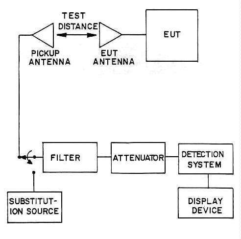
17 Typical Electric Radiation Detection System Test
Setup (U)
18 Narrowband AM Conduction Limit (U)
19 Broadband AM Conduction Limits (U)
20 Narrowband FM Conduction Limits (U)
21 Broadband FM Conduction Limit (U)
22 Narrowband AM Electric Radiation Limits for Controlled Enviroment Tests
(U)
23 Broadband AM Electric Radiation Limit for Controlled Environment Tests
(U)
24 Narrowband FM Electric Radiaiion Limits for Controlled Environment Tests
(U)
25 Broadband FM Electric Radiation Limit for Controlled Environment Tests
(U)
26 FM Electric Radiation Limit Correction Factors (y) (U)
27 Narrowband AM Conduction Limits for xxxxxxxxxxxx (U)
28 Broadband AM Conduction Limits for xxxxxxxxxxxx (U)
29 Narrowband FM Conduction Limits for xxxxxxxxxxxx (U)
30 Broadband FM Conduction Limit for xxxxxxxxxxxx (U)
31 Correction Curve for xxxxxxxxxxxxxxx (U)
32 xxxxxxxxxxxxxxxxxxxxxxxxxxxxxxxx
33 xxxxxxxxxxxxxxxxxxxxxxxxxxxxxxxx
34 xxxxxxxxxxxxxxxxxxxxxxxxxxxxxxxx
35 xxxxxxxxxxxxxxxxxxxxxxxxxxxxxxxx
36 xxxxxxxxxxxxxxxxxxxxxxxxxxxxxxxx
37 xxxxxxxxxxxxxxxxxxxxxxxxxxxxxxxxxxxxxxxxxxxxxxx
38 xxxxxxxxxxxxxxxxxxxxxxxxxxxxxxxxxxxxxxxxxxxxxxx
39 xxxxxxxxxxxxxxxxxxxxxxxxxxxxxxxxxxxxxxxxxxxxxxx
LIST OF TABLES (U)
[Only Tables 2 and 3 were released.]
1 Test Categories (U)
2 Testing Requirement Flow Diagram For xxxxxxxxxxxxxxx Operating At An Installation (U)
3 Testing Requirement Flow Diagram For xxxxxxxxxxxxxxxxx (U)
4 Specific Testing Flow Diagram (U)
FOREWORD (S)
[5 lines redacted.]
1.1 (S) Scope
a. Requirements for equipment testing.b. Requirements for certification of tesz instrumentation and facilities.
c. Requirements for documentation.
d. Limits which provide an acceptable level of NONSTOP security.
1.2 (S) Application
This standard is applicable xxxxxxxxxx which process encrypted analog or digital data and xxxxxxxxxxxxxxxxx unencrypted analog or digital data but which could conceivably be [1 line redacted]. This standard is applicable to the following:
a. xxxxxxxxxxb. xxxxxxxxxx
c. [2 lines redacted.]
d. xxxxxxxxxxxxxxxxxxxxxxxxxx
This document is not for use in optical systems, laser communications, fiber
optics, or wireline transmission. The maximum digital signaling rate applicable
is 75 Mb/s except for [2 lines redacted]. The maximum analog bandwidth is
75 Mhz xxxxxxxxxxxxxxxxxxxxxxxxxx use on land, ships, aircraft and spacecraft.
The standard is intended for both laboratory and field evaluation. Tests
are to be performed in accordance with the procedures presented in the
publication as specified or modified by the contracting Department or Agency.
Tables 2, 3, and 4 present flow diagrams for determining the required testing.
In the text of this document, the term "responsible test organization" may
be substituted for "contractor" or contracting agency if no contract is involved.
Revisions to this standard will be made as appropriate. Comments, corrections and recommendations on the contents of this standard are encouraged. Departments within the Military Services should submit their comments to their respective Cryptologic Agency. Other departments and agencies and Cryptologic Agencies should submit comments to:
Director, National Security Agency
Fort George G. Meade, MD 20755
Attention: S64
Contractors should submit their comments regarding this standard to their
contracting agency.
The effective editions of the following documents at the time of invitation for bid, request f or proposal, or date of test (in the event no contract is involved ) form a part of this Standard to the extent specified herein:
SPECIFICATIONSMILITARYMIL-C-45662. Calibration System Requirements (UNCLASSIFIED)MIL-STD-449, Radio Frequency Spectrum Characteristics, Measurement of (UNCLASSIFIED)
MIL-STD-188, Military Communications System Technical Standards (UNCLASSIFIED)
MIL-STD-462, Measurement of Electromagnetic Interference Characteristics (UNCLASSIFIED)
MIL-STD-831, Preparation of Test Reports (UNCLASSIFIED)
The following listed documents contain information which supplements the information contained in this standard and should be reviewed by personnel involved in the performance of TEMPEST tests. Government personnel may request copies through their SCOCE representative and contractors from their contracting officer.
NACSEM 5100, Compromising Emanations Laboratory Test Standard, Electromagnetics (U) CONFIDENTIAL March 1974NACSEM 5106, Compromising Emanations Analysis Handbook (U) SECRET December 1971
NACSEM 5109, TEMPEST Testing Fundamentals (U) CONFIDENTIAL March 1973
NACSEM 5201, TEMPEST Guidelines for Equipment/ System Design (U) CONFIDENTIAL September 1978
NACSEM 5204, Shielded Enclosures (U) CONFIDENTIAL May 1978
NAG-8/TSEC, TEMPEST Information Memoranda - TIM (U) SECRET December 1967
KAG-30A/TSEC, Compromising Emanations Standard for Cryptographic Equipment (U) SECRET January 1971
Technical Rationale for Angle Modulated TEMPEST Signal Limits S2-TR-75-1 (U) SECRET November 1975
4.1 (U) Glossary
The definitions of terms given in this Glossary are specifically for use
in this standard. In case of conflict between definitions herein and those
in reference documents, the definitions herein govern.
A(U) Ambient Level or Signal
Ambient levels may be classified into two categories:
a. Test Environment Ambient Level: Those levels of radiated and conducted signals and noise existing at a specified test location and time when only the equipment under test is inoperative. Atmospherics, interference from other sources, and circuit noise or other interference generated within the detection system compose the "test environment ambient level".b. Equipment-Under-Test Ambient Level: Radiated and conducted emanations that originate in the equipment under test and which are not compromising emanations.
(U) Amplitude Modulation
Modulation in which the amplitude of a cw signal (carrier) is varied in accordance with a modulating signal.(U) Analog Signal
A signal having no quantized parameters (e.g., amplitude, envelope, phase or frequency).(U) Antenna Factor
A factor (usually in decibels) which, when added to the voltage at the input terminals of the measuring instruments, yields the electric or magnetic field strength in the vicinity of the antenna.(U) Antenna Gain
The ratio of the power radiated by an antenna in a given direction to the power radiated in the same direction by an isotropic radiator, keeping the input power constant. Thus it is a measure of how well the antenna concentrates its radiated power in a given direction.
B
(U) Bit Rate
A general term used to express the transmission rate of digital signals. For purposes of this document it is defined as being numerically equal to the reciprocal of the duration in seconds of the shortest unit interval of the signal. It is expressed in bits per second (b/s). For telegraphic signal codes the term "baud" is synonymous with "bit per second".(U) BLACK Line
A term used to designate all lines of the equipment under test, including power lines, which do not carry intentional RED signals. This definition is only for purposes of this standard and does not necessarily indicate the future use of the particular line.(U) BLACK Signal
Any signal (e.g., control signal. clock or enciphered signal) which could not divulge classified information if recovered and analyzed by an unauthorized interceptor.(U) Bond
A continuous low-impedance electrical path between conducting materials for d.c. and RF signals.(U) Broad-band Detection System
A system specifically chosen to maximize detection sensitivity to emanations contained in a relatively broadband of frequencies (e.g., impulses or aperiodic signals).(U) Broadband Emanation or Emission
Any electromagnetic emanation or ambient signal detected with a broadband tunable or broadnand non-tunable detection system.
C
(U) Cipher or Cipher Text
Unintelligible text or signals generated by the mixing of plaintext and key in a cryptosystem.(U) Cipher System
A cryptosystem in which the cryptographic treatment is applied to plaintext elements of equal length.(U) Combining Triangle
A segment of the key generating circuitry, usually in the form of a logic tree, which generates a sub-key.(U) Compromising Emanations
Unintentional data-related or intelligence-bearing signals (e.g. , plaintext, sub-key, key or keying variable) which, if intercepted and analyzed, disclose the classified information transmitted, received, handled or otherwise processed by any information-processing equipment.(U) Correlated Emanation
A detected emanation which has a causal relationship with any signal or process of known characteristics. Correlated emanations may be compromising under the definition of "Compromising emanation".(U) Cryptographic Equipment
Any equipment employing cryptotechniques or containing cryptographic circuitry or logic.
D
(
S) xxxxxxxxxxxxxxxxxxxxx[1 line redacted.](
S) xxxxxxxxxxxxxxxxxxxxx[1 line redacted.](U) Dry Line
An interface line of the equipment under test, which does not normally carry a signal or from which the normal signal has been removed. This condition may be intentionally induced to prevent masking effects of normal signal voltages by disabling the signal source.
E
(U) Effective Radiated Power (ERP)
A measure of the power being radiated by an antenna as given by: ERP = Power transmitted X Gain of transmitting antenna.(U) Emanation or Emission
Electromagnetic or acoustic energy propagated from a source by radiation or conduction.(U) Encipher
To convert plaintext into unintelligible form by means of a cipher system.(U) Equipment Under Test (EUT)
[1 line redacted.]
F
(U) Final Key
The symbol or signal which is combined with text to produce cipher or vice versa.(U) Frequency Modulation
Angle modulation of a cw signal in which the instantaneous frequency of the modulated signal differs from the unmodulated frequency by an amount proportional to the instantaneous amplitude of the modulating signal.
G
(U) Ground Loop
A path through which currents (e.g., RF currents) may flow from any starting point or source witnin an equipment or test setup through the equipment or test setup and back to the starting point. They are often undesirable since they may cause erroneous test results.(U) Ground Plane
A metal sheet or plate used for circuit returns and a common reference point for electrical signal potentials.
H
(
S) HIJACK [2 lines redacted.]
I
(U) Impulse
A mathematically idealized model of a pulse of short duration relative to the smallest time constant of the circuit to which the pulse is applied. The idealization is made by regarding such a pulse as having infinitesimal width, infinite height and a finite area equal to the area of the pulse being so described. In the frequency domain the ideal impulse is characterized by a uniform single-sided amplitude-density spectrum equal in magnitude to twice the area of the impulse.(U) Impulse Strength
A measure, having dimensions of amplitude per unit bandwidth, of the amplitude-density spectrum of an impulse.Note: In this document, impulse strength is measured in units of microvolts per megahertz (equivalent r.m.s. sinewave), which cause impulse strength to be numerically equal to 0.707 times the magnitude of the amplitude density spectrum which is specified in microvolts per megahertz (peak).
(U) Initial Fill
The sequence of binary digits used to initialize the state of a shift register in a cryptographic equipment.
K
(U) Key
A symbol or sequence of symbols (or electrical or mechanical correlates of symbols) applied to text in order to encrypt or decrypt. Also an element of the arrangement of a crypto-equipment which must be known before encryption or decryption can he carried out. (See Final Key and Sub-Key.)(U) Keying Variable
A setting or initial state of a key generator, such as a key card, key tape, mechanical permuter, or initial fill, which, when varied. changes the generation of key in a predetermined manner.
M
(U ) Masking
The loss of signal detection or analysis capability due to the presence of other higher energy signals or noise.(U) Minimum Discernible Signal (MDS)
A measure of detection system sensitivity which describes the minimum input signal required to provide a discernible signal at the output of the detection system. Some of the factors which affect minimum discernible signal (MDS) are sweep speed of scope, repetition rate of the impulse generator when used as a substitution source, use of the raster generator and the ability of the observer to distinguish between the desired signal and the noise background.(U) Monitor
The reference signal to which detected emanations are compared for determining correlation to plaintext. The monitor is usually a RED signal.
N
(U) Narrowband Detection System
A system specifically chosen to maximize detection sensitivity to emanations contained in a relatively narrowband of frequencies.(U) Narrowband Emanation or Emission
Any emanation or ambient signal detected with a narrowband tunable or narrowband nontunable detection system.(
S) NONSTOP (U)[2 lines redacted.](U) Nontunable
A term used to describe a test. or test instrumentation. in which the frequency coverage is selected in one or more discrete increments i.e., not continuously variable.
P
(U) Plain-Text
Intelligence-hearing text or signals which can be read or acted upon without application of any decryption.(U) Phase Modulation
Phase variations in a carrier or potential carrier.
R
(U) Radio Transmitter
Any device connected to an antenna for the purpose of electromagnetic propagation. This may he a communications or noncommunications device (e.g.. radar, sonar, etc.).(
S) xxxxxxxxxxxxxxxxxxxxxxxxx(S) xxxxxxxxxxxxxxxxxxxxxxxxxxxxxxxxxxxx(
S) xxxxxxxxxxxxxxxxxxxxxxxxx(S) xxxxxxxxxxxxxxxxxxxxxxxxxxxxxxxxxxxx(
S) xxxxxxxxxxxxxxxxxxxxxxxxx(S) [2 lines redacted.](
S) xxxxxxxxxxxxxxxxxxxxxxxxx(S) [3 lines redacted.]
(U) RED Equipment
The equipment processing RED signals that will be exercised when NONSTOP testing the EUT.(U) RED Signal
Any classified plain-text, key, sub-key, initial fill or control signal or traffic flow related, signal, internal or external to the equipment under test, whose content would divulge classified information if recovered by an unauthorized interceptor.(U) RED Signal Line
The term used to designate only those lines that intentionally carry RED signals externally to or from the equipment under test.
S
(U) Sensitivity
The level of the cw signal, which, when applied to the input of the detection system, produces an output signal plus noise-to-noise ratio of 3 dB at the output of the detection system (predetection output for receivers).(U) Shape Factor
The ratio of the 60 dB bandwidth to the 6 dB bandwidth of the frequency response of a detection system.(U) Shielded Test Enclosure
A test area bounded on all sides by a conductive surface to reduce the electromagnetic ambient levels within the area.(U) Short-Cycle Operation
A method employed in TEMPEST testing of cryptographic equipments to facilitate identification of key-correlated emanations. The equipment is modified to generate a repetitive key.(U) Signaling Rate
A general term used to express either the transmission rate of digital signals or the spectral content of analog signals. The units are bits per second for digital signals in serial format, repetitions per second for clock signals and Hertz for analog signals.(U) Site
For the purposes of this document, site shall designate the installation [2 lines redacted].(U) Space Radiation
The phenomena in which electromagnetic signals emanate from the equipment under test into free space.a. Electric Radiation: That portion of the electromagnetic field which is best detected by an unshielded, polarization-sensitive antenna such as the rod, tuned dipole and capacitive probe.b. Magnetic Radiation: That portion of the electromagnetic field which is best detected by an electrostatically-shielded loop antenna.
(U) Spectrum Signature
A plot of detected energy versus frequency over a specified frequency range. A spectrum signature is usually interpreted as being an identifying characteristic of a particular signal.(U) Sub-Key
Key signals produced within an electronic key generator prior to final key, e.g., output of a shift register or combining triangle.
T
(U) TEMPEST
An unclassified term referring to investigations and studies of compromising emanations, it is sometimes used synonymously for the term "compromising emanation", e.g., TEMPEST tests and TEMPEST inspections.(U) Time Modulation
Variations in the time of occurrence of transitions or variations in the rise time or fall time of signal transitions.(U) Tunable
A term used to describe a test, or test instrumentation, in which the frequency coverage is variable within given frequency bounds. Instrumentation which is designed to cover a particular frequency range by digitally tuning in discrete steps shall be considered "tunable".
U
(U) Undesired Signal Data Emanation (USDE)
A compromising emanation which exceeds the limits specified in this standard.(U) Wet Line
Any line operating in its normal mode (i.e., carrying its intended signal).
W
(U) Wobbulate
To shift a cw tone from one frequency to another either in a discrete step or by sluing between the two frequency extremes.
4.2 (U) Abbreviations
AGC - Automatic Gain Control
AM - Amplitude Modulation
BAG - Bit Anomalies Generator
BFO - Beat Frequency Oscillator
b/s - Bits per Second
bw - Bandwidth
cw - Continuous Wave
dB - Decibel
dBmw - Decibel reference to 1 Milliwatt
dBµV/m - Decibel reference to 1Microvolt per meter
(S) xxxxxxxxxxxxxxxxxxxxxxx
(S) xxxxxxxxxxxxxxxxxxx
(S) xxxxxxxxxxxxxx
ER - Electric Radiation
ERP - Effective Radiated Power
EUT - Eouipment Under Test
FDM - Frequency Division Multiplex
deltaf - Change in Frequency or frequency deviation
FM - Frequency Modulation
G - Antenna Gain
HLDS - High Level Detection System
IBW - Impulse Bandwidth
IG - Impulse Generator
MDS - Minimum Discernible Signal
µV - Microvolt
delta0 - Change in Phase
PAD - Pulse Amplitude Demodulator
PM - Phase Modulation
ps - Picosecond
PTO - Pulse Time Demodulator
RF - Radio Frequency
Rb - Broadband data rate used for FM limits
r.m.s. - Root Mean Square
Rn - Narrowband data rate used for FM limits
(S) xxxxxxxxxxx
(S) xxxxxxxxxxx
(S) xxxxxxxxxxxxxxxxxxxxxxxxxx
TDM Time Division Multiplex
(S) xxxxxxxxxxx
(S) xxxxxxxxxxx
USDE - Undesired Signal Data Emanation
deltaV - Change in Voltage
(S) xxxxxxxxxxxxxxxxxxxxxxxxxx
(S) xxxxxxxxxxxxxxxxxxxxxxxxxx
5.1 (U) Control Plan
The NONSTOP control plan shall be a detailed plan outlining the NONSTOP control or reduction program, the engineering design procedures and proposed techniques that will be used to determine conformance with this standard and that will enable the equipment to perform its operational function without emitting Undesired Signal Data Emanations. Approval of the control plan and compliance thereto does not relieve the contractor of the responsibility of meeting the applicable requirements of this standard. Technically justifiable deviations which are being, or are to be, formally processed through contractual channels may be included in the control plan, The control plan shall contain, but not necessarily be limited to, the following items:
a. Frequency Management.(1) A description o f how all operationally intended signals from an equipment will be limited in bandwidth and amplitude to a minimum level consistent with the design requirements, interface considerations, and good engineering design practices.(2) Specific data and respective reasoning to be included are as follows:
(a) Designator (function), purpose, and location of external signal lines.(b) Signal amplitude.
(c) Spectral content of signals.
(d) Design constraints on external signals.
(e) Proposed constraints on external signals.
b. Mechanical Design.
(1) A description of how the materials and construction methods selected for design will provide inherent attenuation to xxxxxxxxxxxxxxxxxxxxxxxxxx which will enable the equipment to meet the requirements of the NONSTOP Specification cited in the contract without conflicting with other mechanical requirements of the equipment.(2) Specific data and respective reasoning to be included are as follows:
(a) Type and thickness of metal to be employed in the construction.(b) Construction techniques.
(c) Compartmentation (RED and BLACK).
(d) Filters and isolation amplifier-buffer.
(1) Mounting technique and location.(2) Type (mechanical design).
(e) RED/BLACK consideration at system interface.
(1) Connectors.(2) Junction Box.
(3) Terminal Strips.
(f) Access, window, and ventilation ports.
(g) RF Gasketing.
(h) Grounding concepts.
(i) Mechanical design of any other factors critical to the NONSTOP effort.
c. Electrical/Electronic Wiring Design.
Specific data and respective reasoning of wiring designs shall include the following:
(1) Designator (function), purpose, and location of critical internal signal lines.(2) Line designator and location of external connectors.
(3) Determination of line type (RED/BLACK and RED/RED), consider intersystem interfaces.
(4) Physical separation (RED/BLACK and RED/RED).
(5) Type of cabling.
(6) Grounding concepts.
(7) RED/BLACK power distribution considerations.
(8) Design of any other wiring factors critical to the NONSTOP effort.
d. Electrical/Electronic Circuit Design.
(1) This section shall include NONSTOP emanation suppression techniques that will be applied to all circuitry which are capable of generating undesirable signal emanations.(2) Specific data and respective reasoning to be included are as follows:
(a) Logic
1 Type2 Signal amplitude
3 Signal rise time
(b) RED interface circuitry (input-output area)
1 Signal amplitude2 Signal rise time
3 Design considerations
(c) Description and isolation characteristics of filters, isolation amplifiers buffers, RED and BLACK.
(d) Shielding and separation techniques proposed in the design and layout of multilayer printed circuit boards.
(e) Power supply design (RED/BLACK isolation).
(f) Placement, grouping, separation, partitioning of circuits.
(g) Grounding concepts.
(h) Input/output clocking.
Note: List which power supply is associated with each clock. If RED circuits are also driven with these power supplies, a list of these red circuits should be noted.
(i) (
S) xxxxxxxxxxxxxxxxx(S) xxxxxxxxxxxxxxxx(
S) xxxxxxxxxxxxxxxx(
S) xxxxxxxxxxxxxxxx4 Signaling rate
(
S) xxxxxxxxxxxxxxxx(
S) xxxxxxxxxxxxxxxx(
S) xxxxxxxxxxxxxxxx(j) List and description of possible circuits susceptible to RED signal coupling.
5.2 (U) Test Plan.
A test plan shall be prepared whic h wi11 detail the means of implemertation and application of the test procedures to be performed to verify compliance with the applicable NONSTOP requirements of this standard. The test plan, when executed, shall demonstrate how the equipment under test (EUT) meets or fails to meet the requirements of this standard. Approval of the test plan by the contracting agency shall precede the start of formal testing. The test plan shall include, but not necessarily be limited to the following items:
a. The name of the organization or firm conducting the test, contracting agency and contract number.b. Nomenclature, identification number, description of function(s), modes of operation and intended use of the EUT.
c, Specific objectives of test.
d. List of EUT signaling rate(s) and RF carrier frequencies to be employed.
e. List of test category(s) in which RED signals appear.
f. List of modes or conditions under which the equipment is to be tested.
(
S) g. List of equipment which interfaces with the xxxxxxxxxxxxxxxxxxxx with a description of normal operating signals.h. List and description of all RED signals which will be used as monitors and any signals which might act as RED signal carriers (clock oscillators, control tone signals. etc.).
i . List of synchronous signals to be employed where and how obtained.
j. Description of the test messages or signals that will be used to exercise the RED equipment during testing.
k. List of tests to be performed on the EUT, including any special tests or procedures specified by the authority sponsoring the tests or deemed necessary by the tester.
1. Recresentative block diagrams (sketches) of EUT and detection system setups for each test showing EUT loads, grounding and detection system output to be monitored, emanation measurement reference points, and antenna and line tap placement.
m. Nomenclature and general characteristics of test instrumentation.
n. Instrumentation detection functions to be used during tests.
o. Detection system bandwidths with applicable frequency ranges.
p. Description of short-cycling procedures and EUT modifications used, if any, with brief assessment of predicted effects in test results.
5.3 (U) Certification Reports.
All certification reports shall be approved by the contracting agency prior to the start of a specific NONSTOP testing program or task. Their purpose shall be to demonstrate that the test instrumentation meets the requirements specified in this standard. At the discretion of the contracting agency, the contents of these reports may be included as an approved part of the test plan. Data sheets containing all pertinent data shall be included in each certification report.5.3.1 (U) Detection System Certification Report.
Each certification report shall include, but not necessarily be limited to, the following applicable items:
a. Name of organization or firm conducting the test, contracting agency and contract number.b. Date(s) of tests.
c. Nomenclature, identification number(s), description of function(s), modes of operation, and intended use of the EUT.
d. Applicable sensitivities, predetection and postdetection bandwidths and frequency ranges of detection systems at each signaling rate to be used in the EUT evaluation in the configuration to be used during applicable tests. These sensitivities and bandwidth data shall be compared with. the appropriate limits and bandwidth bounds, respectively.
e. Pertinent control settings of the test devices and instruments when the sensitivities were measured.
f. All conversion and correction factors used for the applicable test frequency ranges.
g. Block diagrams of the detection systems and calibration signal sources used during the tests.
h. Measurements recorded in the time reference qualification test (6.2.1.5.3).
j. When applicable, an explanation and justification of noncompliance with the sensitivity requirements, also specify the steps which were taken to comply with these requirements.
5.3.2(U) Test Facility and Field Test Environment Certification Report.
This report shall include, but not necessarily be limited to, the following items:
a. Name of organization or firm conducting the certification tests, contracting agency and contract number.b. Address of the organization or firm where test is to be conducted.
c. Location of test facility within plant.
d. Description of facility, e.g., manufacturer and construction of shielded enclosure, description of cable entrances, lighting, available electrical power, etc.
e. Date(s) of certification tests.
f. For ER tests, level vs. frequency plot of electric spatial-ambient signals in the test environment measured with narrowband tunable and broadband tunable detection systems. This data will be presented in graphical form superimposed with the ER limits. Ambient noise measurements are required for both laboratory and field test locations.
g. Description of any unusual or potentially bothersome signal conditions. not evident from graphical data, which might cause masking
h. List of instrumentation, including serial numbers, used during ambient level survey.
i. When applicable, an explanation and justification of noncompliance with the ambient noise level requirements; also specify the steps which were taken to comply with these requirements.
5.3.3 (U) Test Setup Ambient Noise Control Certification Report.
This report shall include, but not necessarily be limited to, the following items:
a. Name of organization or firm conducting certification tests, contracting agency and contract number.b. Date(s) of tests.
c. Functional description of EUT exerciser equipment if different from test plan.
d. For ER tests, level vs. frequency plot of electric spatial ambient signals in the test environment measured with narrowhand tunable and broadband tunable detection systems and with the test setup installed. This data will be presented in graphical form superimposed with the ER limits.
e. Description of any unusual or potentially bothersome ambient noise conditions, not evident from graphical data, which might cause masking.
f. List of instrumentation, including serial numbers, used during ambient noise level survey.
g. Block diagrams of EUT and detection system setups used during amnient noise level survey.
h. When applicable, an explanation and justification of noncompliance with the ambient noise level requirements. Also specify the steps which were taken to comply with these requirements.
5.4 (U) EUT Evaluation Report
At the completion of the NONSTOP tests, a report shall he prepared. If technical support data required for the NONSTOP test report is published in other documents (e.g., certification reports) required by the contract or this standard, they shall be referenced in the test report with the exception of the test plan which must be included as an Appendix. The test report shall contain, as a minimum, the information specified below in j, k, and 1. Data sheets containing all pertinent data shall be included in the report. Each EUT evaluation report shall include the following appropriate items:
a. Name of organization or firm conducting the tests, contracting agency and contract number.b. Date(s) of tests.
c. Test plan as an appendix.
d. Data of most recent calibration of test instrumentation prior to tests.
e. Descriptions of any deviations from test plan.
f. Photographs or pictorial diagrams of detection system and EUT setups with proper identification.
g. Ground plane d.c. bonding resistance.
h. Description of supplementary, theoretical and empirical work which was accomplished.
i. Identification and description o f suppression devices using schematics, performance characteristics and drawings.
j. Test results, including the following items:
(1) Data, including ambient signal and correlated emanation levels graphed or recorded with the appropriate limit. An easily interpreted legend shall be used to identify the various plots.(2) Description of correlated emanations.
(3) Visual recordings, with appropriate reference to test plan items, o f the detected emanations when they can best be described by this means.
(4) Description o f short cycle modifications, if any, including "before" and "after" diagrams of modified circuits.
(5) Description of any phenomenon or emanation encountered during testing which may be outside of the specific requirements of this document, but which may conceivable compromise the classified information being processed by the RED equipment.
k . Tabular summary of USDE which shall include, but not necessarily be limited to the following items:
(1) Identification of line or test medium with reference to appropriate test plan item.(2) Identification of RED signal to which USDE is correlated.
(3) Frequency ranges of USDE.
(4) Maximum level of USDE normalized to appropriate limit. Indicate referenced limit,
(5) Reference sections o f TEMPEST test report or test results that further explain the extent of CE on that particular line or in that, test medium.
l. Description of analysis procedures and techniques used, if any, on correlated emanations.
m. Conclusions reached.
n. Recommendations.
o. Names of test personnel and cognizant government personnel.
5.5 (U) Data Recording Requirements.
Measurements of ambient signals and all emanations correlative to RED signals shall be recorded. Sufficient measurements shall be made to ascertain the energy density spectrum of the detected emanations. The minimum number of ambient level, emanation level, and detection system sensitivity measured and recorded shall be three per decade of frequency over the test frequency ranges specified or three per frequency band (near the beginning, center and end of the band) of the instrumentation being utilized, whichever is the greater number of measurements.
5.5.1 Facility Ambient Levels and Ambient Signal Control Certification Data.Facility and/or field ambient signal levels and ambient signal control certification data shall be recorded as specified in 5.5.2 and 5.5.3 or equivalent.
5.5.2 Detection System Sensitivity Data.
5.5.2.1 AM and FM Detection System Sensitivity Data.Detection system sensitivity certification data shall be recorded on data sheets to include the following.
a. Date data was taken.b. Nomenclature o f detection equipment including serial number and any other designation needed to identify it.
c. Control settings.
d. Test frequency.
e. AM or FM sensitivity.
f. AM or FM limit at test frequency.
5.5.2.2 (
S) xxxxxxxxxxx Detection System Sensitivity Data.(
S) For either xxxxxxxxx detection system certification tests the following data shall be recorded:(S) a. The peak-to-peak ambient voltage excursion and amount of xxxxxxxxxxx, whichever is applicable, which produces a barely perceptible visual signal on the display device for each signaling rate to be used in the EUT evaluation.(
S) b. If RED xxxxxxxxxxxx tests are to be performed, the ambient level and amount of whichever is applicable, which results in a +3 dB signal-plus-ambient-to-ambient ratio for each signaling rate to be used in the EUT evaluation.(
S) c. xxxxxxxxxxxxx detection systems, record the amount of xxxxxxxxxxxxxxxxxxxxxxx which the stable time reference source provides at the signaling, rate of the RED signal monitor. If an external time reference source is used, the amounts of xxxxxxxxxxxx (if applicable) exhibited by the external time reference source shall be recorded. It timing is to be provided to the EUT, the peak-to-peak ambient voltage excursion for each clock source signaling rate shall be recorded. If timing is to be provided to the RED equipment and RED analog xxxx are to be performed, the ambient noise level shall be recorded at the frequency of the RED signal monitor used for each clock source signaling rate.5.5.3 (U) EUT Evaluation Data.
All data taken during testing of the EUT shall be recorded on data sheets as specified below. Where correlated emanations are detected, they shall be measured and recorded whether the level appears to be less than or in excess of the limits. Ambient measurements are to be recorded whether correlated emanations are detected or not.
5.5.3.1 (U) AM FM EUT Evaluation Data.Data sheets used to record test data shall include, but not necessarily be limited to, the following items:
a. Date data was taken.b . Nomenclature of EUT including serial number and any other designation needed to identify it.
c. Test performed.
d. Reference to approved test plan, applicable test plan items, EUT and detection system, test setup.
e. EUT operational mode or any other test conditions describing operation of EUT.
f. Name(s) of person(s) performing tests.
g. Monitor, i.e., RED signal.
h. RED equipment operational mode or any other test conditions describing operation of RED equipment.
i. For each measurement, the following data shall be recorded:
(1) Test frequency.(2) Calibrated source (signal generator, impulse generator) reading in appropriate units.
(3) Conversion and correction factors listed separately and identified.
(4) Adjusted reading (absolute emanation level) in appropriate units.
(5) Specified limit at the particular test frequency.
(6) Identification of emanation (e.g., timing, ambient signal, correlated emanation, receiver noise, 60 Hz, etc.).
(7) Description of detected emanation.
(8) Comments, i.e., any observation considered helpful in identifying or describing detected emanations or special test conditions.
5.5.3.2 (S) xxxxxxx EUT Evaluation Data.
Data sheets used to record test data for eithe, shall include, but not necessarily be limited to, the following items:
a. Date data was taken.b. Nomenclature of EUT including serial number and any other designation needed to identify it.
c. Test performed.
d. Reference to approved test plan, applicable test plan items, EUT and detection system test setup.
e. EUT operational mode or any other test conditions describing operations of EUT.
f. Name(s) of person(s) performing tests.
g. Monitor, i.e., RED signal.
h. RED equipment operational mode or any other test conditions describing operation of RED equipment.
i. For each measurement. the following data shall be recorded:
(1) Signal line and signaling rate of signal under test.(2) State (one or zero) and location of sample command under test.
(3) Monitor (e.g., RED signal) and signaling rate of monitor under test.
(4) Bandwidth (predetection and postdetection) and gain of the detection system.
(5) Specified limit.
(
S) j. For each RED xxxxxxxxxxxxxx test measurement, the following data shall be recorded:(1) For each signal, signaling rate, etc. under test, the peak-to-peak signal plus-ambient and ambient voltage excursion, whenever possible.(2) Percent correct detection when ambient voltage excursJons cannot be made.
(
S) (3) Result of the correlation study (including descriptions) with the amount of xxxxxxxxxxx whichever is applicable.(4) Comments: i.e., any observation helpful in identifying or describing detected emanations or special test conditions.
(
S) k. If RED xxxxxxxxx analog test measurements are to he performed, the following data sha1 be recorded:(1) For each signal, signaling rate, etc. under test, signal plus-ambient noise and ambient-noise levels at the RED analog signal frequency.(
S) (2) Result of correlation study and the amount of xxx associated with each signal-plus-ambient measurement.(3) Comments: i.e., any observation helpful in identifying or describing detected emanations or special test conditions.
(
S) l. If xxxx test measurements are to be performed, the following data shall be recorded:(S) (1) Statement as to whether xxxxxxxxxxxxx was checked.(
S) (2) xxxxxxxxxxxxxxxx(3) Notation of clock source used.
(
S) (4) Record of the xxxxxxxxxxxxxxx gain.
6.1 (U) Data Rate and Test Categories.
a. (S) The requirements of this standard are based primarily on the data rate of any RED signal which could conceivably cause an EUT NONSTOP problem.b.(
S) The signaling rate [2 lines redacted] shall be listed. The signaling rate of analog signals shall be determined by the highest required frequency component contained in the signal and shall be expressed in Hertz. The signaling rate of RED digital signals conveying information in serial and parallel format shall be determined by the reciprocal of the duration in seconds of the shortest unit interval and shall be expressed ib bits per second and parallel information units per second respectively. The signaling rate af cipher signals is determined by the number of information units (ONEs and ZEROs) transmitted per second and shall be expressed in bits per second. The signaling rate of clock signals is determined by the reciprocal of the period in seconds and shall be expressed in repetitions per second.c.(
S) For [AM] STET [brackets and STET by hand] xxxxxxxxxx RED signaling rates as identified in (b) above shall be separated into categories as specified in Table 1 Appendex B. The test category applicable to an equipment processing RED data at only one signaling rate is the category in which the signaling rate appears. If more than one RED signal is being generated, processed or passed simultaneously, tests for emanations correlated to these RED signals shall be performed in each category in which the RED signal appears. If two or more RED signals appear in the same category, the test criteria for the highest RED signaling rate within that category shall be used to search for emanations correlated to all RED signals within the category. If the signaling rate of any of the RED signals is variable, such as would be found in multi-speed equipment, and the operating range is contained within one test category, the highest signaling rate shall be used to determine the test criteria for that particular RED signal. If the operating range of the RED signal covers more than one test category, tests shall be performed in the categories containing the highest and the lowest signaling rates. When searching for [one line redacted].d. (U) For FM tests, test categories do not apply, and only the RED signaling rate need be specified. The signaling rates for FM tests shall be determined as in the AM paragraph above, to allow consistency in test procedures. This is done even though, as mentioned, FM tests are not categorized. It should be pointed out that not only does the signaling rate determine FM test criteria, but also determines applicable limits directly, and not through categories as in the above AM case.
6.2 (U) Instrumentation Requirements.
The detection systems and signal measurement equipment shall meet the performance requirements and operating characteristics specified herein. Measurements of sensitivity and bandwidth shall be performed as specified.
6.2.1 (S) Detection Systems(
S) This standard requires two basic types of detection systems: AM and FM, and xxxxxxxxxxxx which consists of a [1 line redacted]. All systems shall have a 50-ohm input impedance with the exception of electric radiation antenna interface amplifiers, which may be high impedance. Systems shall be selected that meet the frequency range and bandwidths required f or RED signaling rate(s). Systems selected shall meet the inpropriate sensitivity requirement.6.2.1.1 (U) Sensitivity Requirements.
6.2.1.1.1 (U) Sensitivity Requirements for Conducted Tests.The sensitivity for all detection systems shall be equal to or below the appropriate conduction limits specified. Correction and conversion factors shall be added where applicable.
6.2.1.1.2 (U) Sensitivity Requirements for Electric Radiation Tests
If electric radiation tests are to be performed, the sensitivity of the AM and FM detection systems shall be equal to or below the sensitivities shown in Figures 1 through 4 . The FM sensitivities must be corrected for tuned frequency by using Figure 5. Proceed as follows.
a. Locate the tuned frequency and the corresponding correction factor in Figure 5, and add this to the carrier level scale in Figure 3 or 4, whichever is applicable. This now gives the FM curves f or the particular tuned frequency. When measured signals have to be compared to sensitivities, rather than generating a curve for each tuned frequency, an equivalent method follows:b. At a particular tuned frequency, measure the sensitivity and record the carrier level and deviation. Locate the tuned frequency and the corresponding correction factor in Figure 5 and subtract this from the carrier level measured. Now, subtract 10 log (Rn or Rb) from this number and locate this on the scale in either Figure 3 or Figure 4, whichever is applicable. The deviation measured can now be compared to the sensitivity requirement.
6.2.1.2 (U) Sensitivity Measurements, AM Detection Systems.
The sensitivity for AM detection systems shall meet the requirements of paragraph 6.2.1.1.
6.2.1.2.1(U) Narrowband Sensitivity Measurements, AM Detection Systems.a. All sensitivity measurements made with narrowband AM detection systems shall be made with standard signal generators, which are the required calibrated narrowband measurement Standard Narrowband sensitivity is determined by measuring the level of the cw signal which, when applied to the input of the detection system, produces a signal plus noise-to-noise ratio of 3 dB prior to any demodulation (cw sensitivity).b . Three methods are specified for the signal substitution procedures. Method 1 requires a calibrated unmodulated carrier on the substitution signal, and is applicable when measuring the cw sensitivity at the predetection output of tunable detection systems and at the output of nontunable derection systems. Methods 2 and 3 are indirect methods of measuring sensitivity (defined at the predetection output) at the postcetection output of tunable detection systems. Method 2 requires a calibrated sinewave carrier modulated at 30% by 400 Hz or 1000 Hz sinewave as the substitution signal, and applicable when measuring the cw sensitivity at the a.c. or d.c. coupled postdetection output. Method 3 is applicable when measuring the cw sensitivity at the d.c. coupled postdetection output possessing technical limitations which prevent the use of a sinewave carrier modulated by a 400 Hz sinewave. The required substitution signal for Method 3 is a calibrated unmodulated carrier.
Method 1: CW Sensitivity Measurements, Tunable Detection System Without Demodulator and Nontunable Detection System. Measurements shall be made using a calibrated, unmodulated sinewave substitution source. A true r.m.s. a.c. voltmeter of sufficient bandwidth (frequency response extending both below and above the detection system response) shall be connected at the predetection output of the tunable detection system or output of the nontunable detection system. The controls on the detection system shall be adjusted to establish a convenient reading of detection system noise on the output voltmeter. The calibrated source, with the cw frequency equivalent to the center frequency of the detection system, shall then be applied to the detection system input. The substitution source amplitude controls shall be adjusted to produce a reading on the output true r.m.s. a.c. voltmeter 3 dB higher than the reading of detection system noise (signal plus noise-to-noise ratio of 3 dB). The level of the sinewave source output (expressed in dBµV r.m.s.), plus any appropriate conversion and correction factors, is the cw sensitivity.Method 2: CW Sensitivity Measurements, Tunable Detection System With Demodulator. Measurements shall be made using a calibrated sinewave carrier modulated at 30% by a 400 Hz (or 1000 Hz) sinewave. A true r.m.s. a.c. voltmeter and an oscilloscope of sufficient bandwidth (larger than the detection system bandwidth) shall be connected at the postdetection output (a.c.- or d.c.- coupled) of the detection system. The calibrated source with the carrier frequency equivalent to the center frequency of the tuned detection system, shall then be applied to the detection system input. Maintaining a modulation index of 30%, the carrier amplitude of the signal substitution source shall be adjusted to produce an undistorted 400 Hz (or 1000 Hz) waveform on the oscilloscope display, relatively free of noise. Note the reading on the true r.m.s. voltmeter at the postdetection output (output signal plus noise). Maintaining the same carrier amplitude of the signal substitution source, set the modulation index to 0%. Note the reading on the true r.m.s. voltmeter at the postdetection output (detected noise due to cw input signal). Compute the detected signal plus noise-to-detected noise ratio (ratio of first voltmeter reading to second voltmeter reading) in decibels. For accurate measurements, this computed value should be at least 10 dB. The level of the sinewave source output (expressed in dBµV r.m.s.), plus any appropriate conversion and correction factors, minus the above computer detected signal plus noise-to-detected noise ratio in decibels, minus 10.4 dB, is the cw sensitivity.
Method 3. CW Sensitivity Measurements, Tunable Detection System with Demodulator (d.c.-coupled output): Technical Limitations Preventing the Use of a Sinewave Carrier Modulated by a 400 Hz Sinewave as a Substitution Signal. Measurements shall be made using a calibrated, unmodulated sinewave substitution source. A true r.m.s. a.c. voltmeter of sufficient bandwidth (larger than the detection system bandwidth) and a d.c. millivoltmeter shall be connected at the postdetection output (d.c.-coupled) of the detection system. The calibrated source with the cw frequency equivalent to the center frequency of the tuned detection system shall then be applied to the detection system input. The substitution source amplitude controls shall be adjusted to produce a reading on the dc millivoltmeter approximately equal to four times the reading an the true r.m.s. a.c. voltmeter at the postdetection output (i.e., output signal d.c.) to noise (a.c.) ratio approximately equal to four). Compute the actual output signal (d.c.)-to-noise(a.c.) ratio in decibels. The level of the sinewave source output (expressed in dBµV r.m.s.) plus any appropriate conversion and correlation factors, minus the above computed output signal (d.c.)-to-noise (a.c.) ratio in decibels plus 3 dB, is the cw sensitivity.
6.2.1.2.2 (U) Broadband Sensitivity Measurements, AM Detection Systems.
Sensitivity of broadband tunable and broadband nontunable AM detection systems shall be computed by determining the cw sensitivity and converting to broadband sensitivity using the impulse bandwidth (IBW) of the detection system. Method 1 is used for tunable detection systems without demodulation.
Method 2 is used for tunable detection systems with a demodulator. Method 3 is used for nontunable detection systems.
Method 1: Broadband Sensitivity Measurements, Tunable Detection Systems Without Demodulaora. Measure the cw sensitivity (expressed in dBµV r.m.s.) as outlined in 6.2.1.2.1 under Method 1.b. Determine the impulse bandwidth as outlined in 6.2.1.7.2. Express IBW in decibels referenced to MHz, i.e.,
IBWdb = 20 log10 IBW (in MHz)
c. The broadband sensitivity (expressed in dBµV/MHz equivalent r.m.s. sinewave) is equal to the cw sensitivity in decibels, minus the impulse bandwidth in decibels. minus 3 dB.
Method 2: Broadband Sensitivity Measurements, Tunable Detection Systems With Demodulator
a. Measure the cw sensitivity (expressed in dBµV r.m.s.) outlined in 6.2.1.2.1 under Method 2.b. Determine the impulse bandwidth as outlined in 6.2.1.8.2. Express IBW in decibels referenced to MHz, i.e.,
IBWdb = 20 log10 IBW (in MHz)
c . The broadband sensitivity, expressed in dBµV/MHz (equivalent r.m.s. sinewave), is equal to the cw sensitivity in decibels, minus the impulse bandwidth in decibels, minus 3 dB.
Method 3: Broadband Sensitivity Measurements, Nontunable Detection Systems.
a. Measure the cw sensitivity (expressed in dBµV r.m.s.) outlined in 6.2.1.2.1 under Method 1.b. Determine the impulse bandwidth as outlined in 6.2.1.8.2. Express IBW in decibels referenced to MHz: i.e.,
IBWdb = 20 log10 IBW (in MHz)
c. The broadband sensitivity, expressed in dB/µV/MHz (equivalent r.m.s. sinewave), is equal to the cw sensitivity decibels, minus the impulse bandwidth in decibels, minus 3dB.
6.2.1.3 (U) Sensitivity Measurements, FM Detection System.
The FM sensitivity is the minimum deviation necessary, at a designated carrier power level, to produce a 0 dB signal-to-noise ratio at the postdetection FM output. Since this deviation varies drastically with signal level, the measurement should be made at various signal levels to always include the maximum allowable level of the FM detection system. The signal source needed is an FM generator. The following procedure applies:
a. Set the signal level of the FM generator to the desired value.b. Note the r.m.s. voltmeter reading at the postdetection output.
c. Increase the deviation until the voltmeter reading increases 3 dB. This deviation reading is then the minimum deviation for the selected signal input level.
6.2.1.4 (
S) Sensitivity Measurements xxxxxxxxxxxxxxx Systems.(
S) [1 line redacted.] An AM substitution source is used for the measurements.6.2.1.4.1 (S) [1 line redacted.](
S) The sensitivity of the xxxxxxxxxxxxxx detection system shall be measured with a calibrated xx substitution source at each EUT signaling rate to be tested. The following test determines the minimum xxxxxxxxxxx xM variation detectable by the detection systtem. The xxxxx substitution source outout shall be xxxxxxx modulated with a digxxxx signal xxxxxxxxxxxxxxxxxx is connected to the detection system input. The substitution source and xxxxxxxxxxxxxxxxxxxxxx signaling rates shall be the same as the [EUT]STET [brackets and STET by hand] xxxxxxxxxxxxxxxxxxxxxxxxxxxxxxxxxxxxx The predetection, postdetection xxxxx bandwidths (frequency responses) shall be the same as those to be used in the EUT evaluation. Measure the peak-to-peak ambient noise voltage excursion with the output of the substitition xxxxxxxxxxxxxxx Adjust the xxxxxxxxxxxxxxxxxxxxx until the substitution source output xxxxxxxxxxxxxxxxxxx easily detected by the detection system. The xxxxxxxxxxxxxxxxxxxxxxxxxxx shall then be adjusted to produce a barely perceptible visual signal on the oscilloscope. xxxxxxxxxxxxxxxxxxxxxxxxxxxxx determines the xxxxxxxxxxxxx when read from the transfer curve determined in 6.2.2.4.2. xxxxxxxxxxxxxx is then xxxxxxxxxxxxxxxxxx detection system sensitivity at the xxxx ignaling rate tested.6.2.1.4.2 (
S) Analog Sensitivity Measurement of xxxx Detection Systems(
S) The sensitivity of the xxxxxxxxxxxxxxxxxxxxxx shall be measured with a calibrated xx substitution source at each EUT signaling rate to be tested. The following test determines the minimum xxxxxxxxxxxx variation detectable by the detection system. The xxxx substitution source output shall be xxxxxxxxxxxxxxxxxxxxxxxxxxxxxxxxx signal and connected to the detection system input. The substitution source and the cw modulating signal signaling rates shall be the same [as the EUT]STET [bracket and STET by hand] xxxxxxxxxxxxxxxxxxxxxxxxxxx The predetection and the xx bandwidth (frequency response) shall be the same as those to be used in the EUT evaluation. The [2 lines redacted] with the output of the substitution source as the input to the detection system. Mesure the ambient noise level when the output of the substitution source xxxxxxxxxx. Note the signal-plus-ambient noise level at the output of the of the xxxxxxxxxxxxxxxxxxxxxxx of the substitution source. xxxxxxxxxxxxxxxxxxxxxxxxx until a signal-plus-ambient-noise to ambient noise ratio of +3 dB occurs. [1 line redacted] when read from the transfer curve determined in 6.2.2.4.2. This xxxxxxxxxxxxxxxxxxxxxxxxxxxxxx detection system sensitivity at the xxxxxxxxxxxx signaling rate test. As an aid the taster may adjust the voltage of the xxxxxxxxxxxx to obtain a signal-plus-ambient-noise-to-ambient-noise ratio greater than +20 dB (this data is easily extrapolated to obtain a check on the xxxxxxxxxx. Measure the signal-plus-ambient-noise-to-ambient-noise ratio and determine the amount xxxx to obtain the ratio greater than +20 dB.6.2.1.5 (
S) Sensitivity Measurements, xxx Detection Systems(
S) [1 line redacted] subsitution source is used for the measurements.6.2.1.5.1 (S) [1 line redacted.](
S) The sensitivity of the xxxxxxxxxxxxx detection system shall be measured with a substitution source at each EUT signaling rate to be tested. The following test determines the minimum xxxxxxxxxxxxxx variation detectable by the detection system. The xxxx substitution source output shall be [1 line redacted] and connected to the detection system input. The substitution source and the xxxxxxxxxxxxxxxx signaling rates shall be the same as the EUT and xxxxxxxxxxxxxxx to be tested respectively. The predetection, postdetection and xxxxxxxxxxxxxx (frequency responses) shall be the same as those to be used in the EUT evaluation. Measure the peak-to-peak ambient noise voltage excursion with the output of the substitution xxxxxxxxxxxxx. Adjust the voltage xxxxxxxxxxxxxxxxxxxxxxxx until the substitution source output exhibits xxxxxxxxxxxxxxxxxxxxxxxxxxxxxxx by the detection system. The voltage of the xxxxxxxxxxxxxxxxxxxxxxxxx shall then be adjusted to produce a barely perceptible visual signal on the oscilloscope. The peak-to-peak voltage of the xxxxxxxxxxxxxxxxxx determines the xxxxxxxxxxxxx when read from the transfer curve determined in 6.2.2.5.2. This xxxxxx is then the [1 line redacted] signaling rated tested.6.2.1.5.2 (
S) [1 line redacted.](
S) The sensitivity of the xxxxxxxxxxx detection system shall be measured with a xxxxxxxxxxx substitution source (6.3.2.2) at each EUT signaling rate to be tested. The following determines the xxxxxxxxxxxxxxxxx variation detectable by the detection system. The xxxxxx substitution source output shall be xxxxxxxxxxxxxxxxxxxxxxxxxx and is connected to the detection system input. The substitution source xxxxxxxxxxxxxxxxxxxxxx are to me tested respectively. The predetection and xxxxxxxx (frequency responses) shall be the same as those to be used in the EUT evaluation. The narrowband wave analyzer (5 to 200 Hz bandwidth) shall be tuned to the frequency of the xxxxxxxxxxxxxxxxxxxxxxxx. The analyzer shall then be xxxxxxxxxxxxxxxxxxxxxxxxx output of the substitution source as the input to the detection system. Measure the ambient noise level when the output of the substitution source xxxxxxxx. Note the signal-plus-ambient noise level at the [1 line redacted] of the substitution source. Adjust the voltage xxxxxxxxxxxxxxxxxxxxxxxxxxxxx signal-plus-ambient-noise ratio of +3 dB occurs. The peak-to-peak voltage of the xxxxxxxxxxxxxxxxxxxxx when read from the transfer curve determined in 6.2.2.5.2. This xxxxxxxxxxxxxxxxxxxxxxxxxxxxxxxxxxxx detection system sensitivity at the xxxxxxxxxxxxxxxxxx. As an aid, the tester may adjust the voltage to xxxxxxxxxxxxxxxxxxxxxxx to obtain a signal-plus-ambient-noise ratio greater than +20 dB this data is easily extrapolateed to obtain a check xxxxxxxxxxxxxxxxxxx. Measure the signal-plus-ambient-noise ratio and determine the xxxxxxxxxxxxx to obtain the ration greater than +20dB.6.2.1.5.3 (
S) xxxxxxxxxxxx Qualification Test.(
S) The xxxxxxxxxxxxxxxxxxxxxxxxxxxxxxxxxxx shall be tested to ensure that the source meets the requirements. If the xxxxxxxxxxxxxxxxx from the signal under test. A test which determines if the xxxxxxxxxxxxxxxxxxxxxxxxxxx qualifies shall be performed by the following steps:(S) a. The substitution source output shall be [1 line redacted].(
S) b. The substitution source and the xxxxxxxxxxxxxxxxxxx shall be the same as the EUT and xxxxxxxxxxxxxxxxxxxxxxxxxxx(
S) c. Apply the xxxxxxxxxxxxxxxxxxxxxxxxxxx to the vertical input of the oscilloscope.(
S) d. [2 lines redacted.](
S) e. Adjust the peak-to-peak voltage of the [1 line redacted] can easily be seen on the oscilloscope.(
S) f. Determine and record the amount of peak-to-peak xxxxxxxx.(
S) g. Connect the substitution source output to the xxxxxxxxxxxxxxxxxxxxxxx.(
S) h. Apply the xxxxxxxxx source output to the vertical input of the oscilloscope.(
S) i. With the oscilloscope [1 line redacted] record the amount of xxxxxxxx.(
S) j. If xxxxxxxxxxxxx are to be performed, the ubstitution source output shall then be [1 line redacted].(
S) k. The substitution source xxxxxxxxxxxxxxxxxxxx shall be the same as the EUT [1 line redacted].l. Repeat steps c through i.
(
S) m. xxxxxxxxxxxxxxxxxxxxxx qualifies if the amount of peak-to-peak time variation recorded in step i is equal to or less than one-fifth the amount of peak-to-peak xxxxxxxxxxx in step f.(
S) xxxxxxxxxxxxxxxxxxxxxxxxxx is supplied from an external source, xxxxxxxxxxxxxxxxxxxxxxxxxxxxx test shall be performed at each signaling rate to be tested to ensure that the [2 lines redacted] signaling rate to be tested shall also be performed xxxxxxxxxxxxxxxxxxxxx qualifies if the amount of [1 line redacted].6.2.1.6 (
S) Bandwidth Requirements.(S) a. The AM bandwidth requirements are based on the RED signaling rates. A 1 kHz signaling rate shall be used to determine the test criteria for analog speech signals. The bandwidths for narrowband AM detection systems not employing a demodulator shall comply with the requirements specified in Figure 7. Bandwidths for broadband AM detection systems not employing a demodulator shall comply with the requirements of Figure 8. Bandwidths for narrowband and broadband detection systems which employ a demodulator shall be one-half those specified in Figures 7 and 8.,respectively. When a demodulator is used in the detection system, the predetection bandwidth shall be no greater than ten times the postdetection bandwidth used for a particular test. The bandwidth of the broadband detection system shall always be at least five times greater than the bandwidth of the narrowband detection system at corresponding frequencies.(
S) b . The FM bandwidth requirements are also based on the xx signaling rates, However, there are separate requirements on the predetection and postdetection bandwidths which are unlike the AM bandwidth requirements in which total system bandwidth is of importance. A 1 kHz signaling rate shall be used to determine the test criteria for analog speech signals. The bandwidths for narrowband narrow deviation FM detection systems are given in Figure 9, and the permissable narrowband wide deviation FM bandwidths are given in Figure 10. The bandwidths for broadband FM detection system are given in Figure 11. The predetection bandwidth for both narrowband wide deviation and broadband FM detection systems must at least five times greater than the bandwidth used for the narrowband narrow deviation FM detection systems at corresponding frequencies.(
S) c. The xx bandwidth requirements are based on the [1 line redacted] A 1 kHz signaling rate shall be used to determine the test criteria for analog speech equipment. Bandwidth requirements for xxxxxxxxxxxxxxx detection systems shall comply with the requirements specified in Figure 12. Bandwidths shall be measured in accordance width 6.2.1.7 through 6.2.1.11 as appropriate if:(1) The bandwidth is not known.(2) There is reason to doubt the manufacturer's published bandwidth figures.
(3) Request by the authority sponsoring the tests.
6.2.1.7 (U) Bandwidth Measurements, Predetection
The 6 dB and impulse bandwidths shall be measured in accordance with the following paragraphs.
6.2.1.7.1 (U) 6 dB Bandwidth Measurements, Predetection.The minimum number of bandwidth measurements for tunable detection systems not emoploying a demodulator shall be two per decade of frequency or one per tuning band (near the center), whichever is the greater number of readings. The bandwidth of these detection systems shall be measured as follows:
a. Apply the output of a f requency and amplitude calibrated unmodulated sinewave generator to the input of the detection system.b Adjust the carrier frequency of the cw generator around the center frequency of the detection system until the maximum output level of the detection system is observed at the same port used during NONSTOP testing. Record the output level with a peak-responding voltmeter calibrated in r.m.s. volts. (A meter calibrated in decibels would facilitate measurement.)
c . Maintaining the same cw generator carrier amplitude and detection system tuned-center frequency as in Par. b., reduce the cw generator carrier frequency until the output level of the detection system decreases 6 dB from the level obtained in par. b. or until the carrier frequency is essentially zero frequency (such as would occur at a detection system output with d.c. response), whichever comes first. Record this frequency.
d. Repeat par. c., except increase the carrier frequency until the output level decreases 6 dB from the level obtained in par. b. Record this frequency.
e. Subtract the frequency recorded in par. c. , from that in par. d. . to obtain the detection system bandwidth.
f. Repeat at other detection system tuned-center frequencies as required by this paragraph.
6.2.1.7.2 (U) Impulse Bandwidth Measurements, Predetection.
The minimum number of impulse bandwidth measurements for tunable detection systems not employing a demodulator shall he two per decade of frequency or one tuning band (near the center). whichever is the greater number of readings. The impulse bandwidth of these detection systems shall be measured as follows:
a. Apply the output of a frequency and amplitude- calibrated unmodulated sinewave generator to the input of the detection system.b. Adjust the carrier frequency of the cw generator around the center frequency of the detection system until the maximum output level of the detection system is observed on an oscilloscope at the same port used during NONSTOP testing. Record the output peak-to-peak amplitude observed on the oscilloscope and the signal level level in r.m.s. volts of the cw sinewave applied at the input of the detection system.
c. Disconnect the cw generator and apply the output of a calibrated impulse generator to the input of the detection system. Set the IG repetition rate to any convenient rate less than one-fifth of the nominal detection system bandwidth.
d. Adjust the IG output level so that the peak-to-peak waveform displayed on the oscilloscope (all the output of the detection system) is equal to the peak-to-peak amplitude of the cw waveform recorded in par. b. Record the level (in volts (equivalent r.m.s. sinewave)/MHz) of the impulsive signal applied at the input of the detection system.
e. Calibrate the impulse bandwidth of the detection system with the following formula.
IBW = (Sinewave input signal level in r.m.s.-volts. recorded in par. b,)
(Impulse input signal level in volts (equivalent r.m.s. sinewave)/ MHz, recorded in par. d.)f. Repeat at other detection system tuned-center frequencies as required by this paragraph.
6.2.1.8 (U) Bandwidth Measurement AM Postdetection.
The minimum number of bandwidth measurements for tunable, heterodyne detection systems employing a demodulator shall be two per decade of frequency or one per tuning band (near the center) whichever is the greater number of readings. The 6 dB and impulse bandwidth shall be measured in accordance with the following paragraphs.
6.2.1.8.1 (U) 6 dB Bandwidth Measurement.The 6 dB bandwidth of detection systems shall be measured as follows:
a. Apply the output of a frequency and amplitude calibrated sinewave generator to the input of the detection system. The generator output sinewave shall be amplitude modulated with a sinewave using any convenient modulation index which shall be maintained constant over the required frequency range. The frequency of the modulating sinewave shall he adjustable over the bandpass of the detection system.b. Adjust the carrier frequency of the cw generator around the tuned -center of the de tec t ion system until the maximum level of the modulating signal is observed at the same output port o f th e detection system used during NONSTOP testing.
c. Adjust the frequency of the modulating signal until the maximum output level of the detection system is observed. Record the output level with a peak-responding voltmeter calibrated in r.m.s. volts. (A meter calibrated in decibels would facilitate measurements.)
d. Maintaining the same cw generator carrier frequency, carrier amplitude and modulation index, and the same detection system tuned frequency as in par c., reduce the frequency of the modulating signal until the output of the detection system decreases 6 dB from the level ontained in par. c. or until the modulating frequency is essentially zero frequency (such as would occur in a d.c.-coupled demodulator), whichever comes first. Record this frequency.
e. Increase the frequency until the output of the detection system decreases 6 dB from the level obtained in par. c. Record this frequency.
f. Subtract the frequency recorded in par. d., from that in par. e. to obtain the detection system bandwidth.
g. Repeat at other detection system tuned-center frequencies as required by this paragraph.
6.2.1.8.2 (U) Impulse Bandwidth Measurement.
The impulse bandwidth of detection systems shall be measured as follows:
a. Apply the output of a frequency-and-amplitude-calibrated AM sinewave generator (meeting the requirements of 6.2.2.2) to the input of the detection system. The generator output signal snall he amplitude-modulated 30% with a sinewave of 400 Hz (or 1000 Hz).b. Adjust the carrier frequency of the AM sinewave generator around the center frequency of the detection system until the maximum output level of the detected signal is observed at the same cutout port of the detection system used during NONSTOP testing. Record the output peak-to-peak amplitude observed on the oscilloscope and the signal level in r.m.s. volts of the AM sinewave applied at the input of the detection system.
c. Disconnect the AM sinewave generator and apply the output of a calibrated impulse generator to the input of the detection system. Set the IG repetition rate to any convenient rate less than two-fifths of the nominal detection system bandwidth.
d. Adjust the IG output level so that the peak magnitude of the waveform displayed on the oscilloscope (at the detection system output) is equal to one-half the peak-to-peak amplitude of the detected sinewave recorded in par. b. Record the level in volts (equivalent r.m.s. sinewave/MHz), of the impulsive signal applied at the input of the detection system.
e. Calculate the impulse bandwidth of the detection system with the following formula:
IBW = 0.3 (AM Sinewave input signal level in r.m.s. volts recorded in par. b.)
__________________________________________________________(impulsive input signal level in volts (equivalent r.m.s. sinewave MHz recorded in par. d.) f . Repeat at other detection system tuned-center frequencies as required by this paragraph.
6.2.1.9 (U) Bandwidth Measurement, FM Postdetection.
The minimum number of bandwidth measurements for FM detection systems shall be two per decade of frequency or one per tuning band (near the center), whichever is the greater number of readings. The FM postdetection bandwidth shall be measured as follows:
a. Set the FM generator deviation to zero and tune the generator carrier frequency to the selected test frequency. Reduce the FM generator outputsignal level until the reading on the r.m.s. voltmeter at the FM video output is at a maximum. Note this reading.b. Increase the FM generator output signal level until the true r.m.s. voltmeter indicates 20 dB below the reading noted in par. a. This is the input signal level corresponding to 20 dB of quieting.
c. Adjust the frequency of the modulation signal to one-fourth of the nominal predetection bandwidth or the highest modulating frequency the FM generator will accomodate, whichever is less.
d. Adjust the modulation to produce a deviation of one-fourth of the FM discriminator bandwidth or the maximum deviation of the FM generator, whichever is less.
e. While maintaining a constant deviation, decrease the modulation frequency until the video output voltmeter reaches a maximum.
f. Readjust the modulation voltage to produce a deviation equal to one-fifth the modulation frequency.
g. Note the FM video output signal level as indicated by the voltmeter at the FM video autput.
h. Increase the frequency of the modulation signal until the FM postdetection output signal level falls 6 dB below the level as noted in par. g. Record this frequency as the FM postdetection bandwidth.
6.2.1.10 (U) Bandwidth Measurements, FM discriminator.
There are two methods for measuring the FM discriminator bandwidth; one requires a cw generator and the other requires an FM generator.
Method 1: CW Generator.
a. Tune the cw generator to the selected test frequency. Reduce the cw generator output signal level until the reading on the r.m.s. voltmeter at the FM video output is at a maximum. Note this reading.b. Increase the cw generator output signal level until the r.m.s. voltmeter indicates 20 dB below the reading noted in par. a. This is the inout level corresponding to 20 dB of quieting.
c. Tune the cw generator through the receiver passband while observing the d.c. voltmeter indication at the FM video output.
d. Tune the cw generator to the frequency at which the d.c. voltmeter indicates a maximum peak. Note the frequency f1 of the cw generator as indicated on the frequency counter.
e. Tune the cw generator to the frequency at which the d.c. voltmeter indicates a minimum Note the frequency f2 of the cw generator.
f. Compute and record the FM discriminator bandwidth as follows:
FM Discriminator Bandwidth = /f1 - f2
Method 2: FM Generator.
a. Set the FM generator deviation to zero and tune the generator carrier frequency to the selected test frequency. Reduce the FM generator output signal level until the reading on the r.m.s. voltmeter at the FM video output is at a maximum. Note this reading.b. Increase the FM generator output signal level until the true r.m.s. voltmeter indicates 20 dB below the reading noted in par. a. This is the input level corresponding to 20 dB of quieting.
c. Adjust the modulation frequency and deviation to produce a suitable display of the FM video output signal on the oscilloscope.
d. Start increasing the deviation of the input signal, and while observing the demodulated signal on the oscilloscope, continue increasing the deviation until the response begins to flatten at the peaks.
e. Multiply the deviation by 2 and record as the FM discriminator bandwidth.
6.2.1.11 (
S) Bandwidth Measurements of Specific xxxxxxxxxx Circuits.The two circuits which are special xxxxxxxxxxxxxxxx detection svstems, are the [1 line redacted]. Bandwidth measurements for these shall he made in accordance with the following paragraphs:
6.2.1.11.1 (S) Bandwidth Measurement of xxxxxxxxxx(
S) The bandwidth of the xxxxxxxxxxxx shall be checked as follows:(S) a. The substituion source output shall be [1 line redacted].(
S) b. The substitution source xxxxxxxxxxxxxxxxxxxxxxxxxxxxx shall be the largest signal line under test and xxxxxxxxxxxxxxxxxxxxxxxxxxxx(
S) c. The amplitude variation of the substitution source output shall he detected using xxxxx.(
S) d. The xxxxxx is to be applied to the vertical input of an oscilloscope and the amount of xxxxxxxxxxxx adjusted so that the detected signal can easily be seen on the oscilloscope.(
S) e. Measure the peak-to-peak voltage excursion and compare this measurement with the amount of xxxxxxxxxxxxxxxxxxxxxxxxxxxxxxxxxxxxx.(
S) f. The xxxxxxxxxxxx is sufficient if the measured voltage in par. e. is within +10% of the calculated voltage of par. e.6.2.1.11.2 (
S) Bandwidth Measurement of xxxxxxxxxxxxxxxxxxxThe bandwidth of xxxxxxxxxxxxxxxx shall be checked as follows:
(S) a. The substitution source output shall be [1 line redacted].(
S) b. The substitution source and xxxxxxxxxxxxxxxxxxxxxxxxxx shall be the largest signal line under test and xxxxxxxxxxxxxxxxxxxxxxxxxxxxx(
S) c. xxxxxxxxxxxxxxxxxxxxxx of the substitution source output shall he compared with xxxxxxxxxxxxxxxxxxxxxxxxxxxxxxxxxxx(
S) d. xxxxxxxxxx is to he applied to the vertical input of an oscilloscope and the xxxxxxxxxxxxxx so that the detected signal can easily he seen on the oscilloscope.(
S) e. Measure the peak-to-peak voltage excursion and compare the measurement with the amount of[1 line redacted].(
S) f. xxxxxxxxxxx is sufficient if the measured voltage in par. e. is within ±10% of the calculated voltage of par. e.
6.2.2 (U) Signal Measurement Standards.The acceptable calibration generators for the purpose of this standard are. AM generators, FM generators, impulse generators, AM substitution sources, TM substitution sources, and sinewave generators.
6.2.2.1 (U) AM Generators.6.2.2.1.1 (U) Requirements.An amplitude modulated RF source shall be used to make AM narrowband measurements and to ensure that the AM detection systems comply with the senseitivity requirements in 6.2.1.1. The AM generator shall conform to the following requirements:
a. The amount of amplitude modulation shall he calibrated with respect to the r.m.s. voltage of the modulating signal in accordance with 6.2.2.1.2.b. The range of amplitude modulation shall he continuously variable from zero to a value equal to or exceeding 30%.
c. The relationship between amplitude modulation and modulating signal voltage shall he linear.
d. The AM generator output power level of the fundamental signal frequencv shall be capable of being equal to the power level of the carrier at which point the calibration signal is inserted into the detection system.
e. Harmonic and spurious outputs shall be 30 dB or more below the power level of the fundamental signal frequency.
f. The ambient noise of the AM generator output shall not restrict the detection system in complying with the sensitivity requirements in 6.2.1.1.
g. The bandwidth of the generator shall he such that the modulating signal frequency can be adjusted over the bandpass of the AM detection system. (This requirement may be waived when detection bandwidths exceed presently available generator modulating frequencies.)
h. Frequency accuracy: +2 percent.
i. Amplitude accuracy: +10 percent.
6.2.2.1.2 (U) Calibration.
The relationship between the modulation signal r.m.s. voltage and the r.m.s. AM sideband level small be determined. A plot depicting the AM r.m.s. sideband level as the ordinate and the modulating signal r.m.s. voltage as the abscissa shall be derived. (The extension of the straight line must pass through this origin.) If the peak amplitude variation (with a sinewave modulating signal) can he determined, the AM r.m.s. sideband level is found by dividing the peak amplitude variation by 2.
Note: If the transfer curve is dependent upon the AM generator output power level, the AM generator shall be calibrated for each RF carrier power to he used in the AM tests.
6.2.2.2 (U) FM Generators.
6.2.2.2.1 (U) Requirements.A frequency modulated RF source shall be used to make narrowband FM measurements and to ensure that the FM detection systems comply with the sensitivity requirements in 6.2.1.1. The FM generator shall conform to the following requirements:
a. The amount of frequency modulation shall be calibrated with respect to the r.m.s. voltage of the modulating signal in accordance with 6.2.2.2.2.b. The range of frequency deviation shall he continuously variable from zero to a value equal to or exceeding the signaling rate, where presently available equipments permit.
c. The relationship between frequency deviation and modulating signal voltage shall he linear.
d. The FM generator output power level of the fundamental signal frequency shall be capable of being equal to the power level of the carrier at which point the calibration signal is inserted into the detection system.
e. Harmonic and spurious outputs shall be 30 dB or more below the power level of the fundamental signal frequency.
f. The ambient noise and frequency stability of the FM generator output shall not restrict the detection system in complying with the sensitivity requirement in 6.2.1.1.
g. The bandwidth of the generator shall be such that the modulating signal frequency can be adjusted over the bandpass of the FM detection system, when present FM instrumentation permits.
h. Frequency accuracy: +2 percent.
i. Amplitude accuracy: +10 percent.
6.2.2.2.2 (U) Calibration.
The relationship between the modulating signal r.m.s. voltage and the r.m.s. frequency deviation shall be determined. A plot depicting the r.m.s. frequency deviation as the ordinate and the modulating signal r.m.s. voltage as the abscissa shall be derived. (The extension of the straight line must pass through the origin.) If the peak frequency deviation (with a sinewave modulating signal) can be determined, the r.m.s. frequency deviation is found by dividing the peak frequency deviation by 2. A suggested method of calibrating an FM generator involves taking advantage of the carrier and sideband nulls by observation on a spectrum analyzer. In order to obtain the peak frequency deviation per unit of modulating signal r.m.s. voltage, the modulating frequency should be held constant and the amplitude varied from zero. Whenever the carrier or a particular pair of sideoands are nulled out, e.g., disappear as observed on the spectrum analyzer, a modulation r.m.s. voltage measurement is made. It is also necessary to observe the number of nulled sidebands and the number of times that particular sideband (or carrier) has been nulled as the modulating voltage varies. With this information and using a table of Bessel zero's, the deviation can be obtained. The number from the Bessel zero's table must be multiplied by the modulating frequency to obtain the peak frequency deviation for a particular modulating signal r.m.s. voltage. The transfer curve of r.m.s. frequency deviation vs. modulating signal r.m.s. voltage can thus be derived.
6.2.2.3 (U) Impulse Generator.
6.2.2.3.1(U) Requirements.An impulse generator shall be used to make broadband measurements. Impulse generators shall conform to the following requirements:
a. Calibrated in dBµV/MHz (equivalent r.m.s. sinewave) (peak minus 3 dB) to a 50-ohm resistive load.b. Flat spectrum (+2 dB) over its usable frequency range.
c. Amplitude accuracy: +2 dB.
6.2.2.3.2 (U) Calibration. The impulse generator shall be calibrated by one of the following four methods:
Method 1:a. Apply the output to the impulse generator to be calibrated to the input an amplitude-linear receiver having synchronously-tuned, less-than-critically coupled circuits. Radio interference field intensity receivers are satisfactory for this purpose if their impulse bandwidth is at least five times the repetition rate of the impulse generator. Any automatic gain control (AGC) system shall he disabled and the AGC line firmly referred to ground with a low-impedance voltage source of appropriate value.b. Obtain an oscilloscope pattern of the overall receiver response at the IF output. The oscilloscope controls shall be so adjusted that the pattern is as large as possible within the calibrated area on the face plate. Either photograph or trace the pattern. Record the oscilloscope sweep speed setting. (The sweep speed shall he calibrated accurately.)
c. Use a planimeter or other integrating device to determine the area of the positive portion of the major lobe of the response waveform. (More accuracy can be obtained by summing the area under the odd-numbered lobes and subtracting from it the total area under the even-numbered lobes.) This operation shall he carried out at least five times and the average of the readings taken as the area.
d. Calculate the impulse bandwidth of the receiver in accordance with the following formula:
IBW in MHz = Pattern height* in cm X10n [exponential is blurred]
________________________________________________(Pattern area * in cm/2)(sweep speed in sec/cm) *Refers only to positive portion of response waveform.
e . Connect a calibrated sinewave generator to the receiver. Tune the generator to the receiver's tuned frequency and adjust the output until the peak pattern height is the same as that obtained with the impulse generator in pars. a. and b. Record the output of the sinewave generator in microvolts (r.m.s.).
f. Calculate 20 log10 (e/d) where e and d are the results obtained in pars. e. and d. above expressed in microvolts (r.m.s.) and megahertz (MHz) respectively. This calculation gives the spectral intensity of the impulse generator output in dBµV/MHz (equivalent r.m.s. sinewave).
Method 2:
a. Select a bandpass or low-pass filter with the following characteristics:(1) Minimum upper roll-off of 18 dB/octave.(2) Maximum upper 3 dB cutoff point which is 10% of the reciprocal of the width of the driving impulse (from the IG to the calibrated) or 80% of the bandpass of the oscilloscope in use whichever is less.
(3) Passband wide enough to permit passage of sufficient energy so that the peak voltage of the output waveform can he accurately read on the oscilloscope.
(4) 50-ohm input and output impedance in the passband.
b. Determine the impulse bandwidth (IBW) of the filter employing the procedures specified in Method 1 above, pars. a. through d., substituting the word "filter" for "receiver". (Once the IBW of the filter has been measured, the filter may be used to calibrate any number of IGs; however, the IBW shall be rechecked in accordance with 6.2.2.3.2.
c. Terminate the output of the IG to be calibrated with a 6-db (minimum), 50-ohm pad and connect it to the input of the filter.
d. Terminate the output of the filter with a 50-ohm resistive load and connect it to the vertical input of the oscilloscope.
e. Record the peak voltage of the filter output on the oscilloscope in microvolts.
f. Calculate:
20 log10 (e/b) + Pad Loss -3 dB + Filter Insertion Loss where e and b are the results obtained in pars. e. and b. above expressed in microvolts (r.m.s. ) and megaHertz respectively. This calculation gives the spectral intensity of the impulse generator output in dBµV/MHz (equivalent r.m.s. sinewave).Method 3:
a. Apply the output of the impulse generator to be calibrated to the input of a spectrum analyzer having the following characteristics:(1) Known impulse bandwidths.(2) Absolute amplitude accuracy equal to or better than +2 dB.
b. Select a spectrum analyzer bandwidth which is at least five times the repetition rate of the impulse generator but no larger than one-tenth the usable spectrum of the impulse generator. Select a scan time in seconds/division no less than 10/repetition rate (Hz) to ensure ten impulse responses per division.
c. Add any conversion factors to the spectrum analyzer displayed voltage needed to convert dBm to dBµV. Subtract the impulse bandwidth of the spectrum analyzer in decibels with reference to 1 MHz to this value to convert to dBµV/MHz and subtract 3 dB to convert the reading to dBµV/MHz (equivalent r.m.s. sinewave) which is the spectral intensity of the impulse generator output.
Method 4:
Compare the output of the IG to be calibrated with the output of another IG which has previously been calibrated in accordance with Method 1 or Method 2 within the last six months.6.2.2.4. (
S) AM Substitution Source.6.2.2.4.1 (S) Requirements.(
S) xxxxxxxxxxxxx calibration generator, for the purposes of this standard, is the substitution source. At the present time the xxxxxxxxxxxxxxxxxxxxxxxx is the only substitution source meeting the requirements. This xxxxxxxxxxxxxxxxxxxxxxxxxxxxxxxxxx. The AM substitution source shall be used to ensure that the detection system complies with the sensitivity requirements in 6.2.1.1. The substitution source shall conform to the following requirements.(S) a. The substitution source shall he capable of xxxxxxxxxxxxxxxxxxxxxx.(
S) b. The substitution source shall be capable of xxxxxxxxxxxxxxx.(
S) c.xxxxxxxxxxxxxxxxxxxxxxxxxxxxxxxxxxxxxxxx peak-topeak voltage excursion shall determine the amount of xxxxxxxxxxxxxxxxxxxxxxxxxxxxxx.(
S) d. The xxxxxxxxxxxxxxxxxxx shall he calibrated with respect to the peak-to-peak voltage excursion of xxxxxxxxxxxxxxxxxxx in accordance with 6.2.2.2.(
S) e. The range of xxxxxxxxxxxxxxx shall be continuously variable from zero to a value at least a tenth of a volt.(
S) f. The relationship between xxxxxxxxxxxxxxxxxxxxxxxxxxxxxxxxxxxxxxxxxxxxxxxx.(
S) g. The xxxxxxxxxxxxx and ambient noise of the substitution source output shall not restrict the detection system in complying with the sensitivity requirements in 6.2.1.1.h . Signaling rate accuracy: +2 percent.
i. Amplitude accuracy: +10 percent.
6.2.2.4.2 (U) Calibration.
The AM substitution source shall be calibrated as follows.
a. The xxxxxxxxxxxxx shall be amplitude modulated with a single tone or square wave with a maximum signaling rate of 0.1 times the signaling rate of the modulated output signal.b. Apply the amplitude modulated output of the substitution source to the vertical input of an oscilloscope.
c. Adjust the peak-to-peak voltage of the modulating signal so that the amplitude modulation can easily be seen on the oscilloscope.
d. Determine and record the amount of amplitude variation and the peak-to-peak voltage of the modulating signal.
e. Decrease or increase the amount of amplitude variation and repeat par. d. f or ten points over at least a decade change in the peak-to-peak voltage of the modulatings signal.
f. Plot these points using the amplitude variation as the ordinate and the peak-to-peak voltage of the modulating signal as the abscissa. (The extension of the straight line must pass through the origin.) The slope of the straight line defined by these points is the gain of the substitution source.
6.2.2.5 (
S) xx Substitution Source.6.2.2.5.1 (S) Requirements.(
S) The acceptable xxx calibration generator, for the purposes of this standard, is the xxx substitution source. At the present time, the xxxxxxxxxxxxxxxxxxxxxxxxxxxxxxxx source meeting the requirements. xxxxxxxxxxxxxxxxxxxxxxxxxxxxxxxxxx. The xxxxxxxxxxxxxxxx source shall be used to make xxxxxxxxxxxxxxxxxx and to ensure that the detection system complies with the sensitivity requirements in 6.2.1.1. The substitution source shall conform to the following requirements.(S) a. The substitution source shall be capable of [1 line redacted].(
S) b. The substitution source shall be capable of generating xxxxxxxxxxxxxxx.(
S) c. xxxxxxxxxxxxxxxxxxxxxxxxxxxxxxxxxx peak-to-peak voltage excursion shall determine the amount of xxxxxxxxxxxxxxxxx at the substitution source output.(
S) d. The amount of xxxxxxxxxxxxx shall be calibrated with respect to the peak-to-peak voltage excursion of the xxxxxxxxxxxxxxxxxxxx in accordance with 6.2.2.5.2.(
S) e. The range of xxxxxxxxxxx shall he continuously variable from zero to 5% of xxxxxxxxxxxxxxxxxxx.(
S) f. [1 line redacted.](
S) g. The xxxxxxxxxxxx and ambient noise of the substitution source output shall not restrict the detection system in complying with the sensitivity requirements in 6.2.1.1.h. Signaling rate accuracy: +2 percent.
i. Amplitude accuracy: +10 percent.
6.2.2.5.2 Calibration.
(
S) The xx substitution source shall be calibrated as follows:(S) a. The output xxxxxxxxxxxxxx shall be xxxxxxxxxxxx with a single tone or square wave with a maximum xxxxxxxxxxxxxxxxxxxxxxxxxx of the modulated output signal.(
S) b. Apply the xxxxxxxxxxxxx output of the substitution source to the vertical input of an oscilloscope.c. Trigger the oscilloscope with an unmodulated periodic signal which is in phase with the substitution source output (when unmodulated).
(
S) d. Adjust the peak-to-peak voltage of the xxxxxxxxxxxxxxxxxxxxxxxxxx can easily be seen on the oscilloscope(
S) e. Determine and record the amount of [1 line redacted].(
S) f. Decrease or increase the xxxxxxxxxxxxxxxxxx par. e. for ten points over at least a decade change in peak-to-peak voltage of xxxxxxxxxxxxxxx.(
S) g. Plot these points xxxxxxxxxxxxxxxxxxxxxx the peak-to-peak of xxxxxxxxxxxxxx as the abscissa. (The extension of the straight line must pass tnrough the the origin. ) The slope of the straight line defined by these points is the transfer factor of the substitution source xxxxxxxxxxxxx.6.2.2.6 (U) Sinewave Generators.
Sinewave generators shall conform to the following requirements:
a. Frequency accuracy: +2 percent.b . Harmonic and spurious outputs 30 dB or more down from power level of the fundamental signal frequency.
c. Amplitude accuracy: +10 percent.
6.2.3 (U) Calibration Requirements and Operational Check.
Prior to the beginning of EUT evaluation, all test instrumentation shall be checked to assure proper operation in accordance with the manufacturer's specification. All instrumentation used as signal measurement standards and all calibrated metering and display devices shall be calibrated under an approved program in accordance with MIL-C-45662. After the above initial check and calibration, the instrumentation shall he checked at least once every six months or immediately after exposure to conditions which might affect calibration. The detection system sensitivity shall be spot-checked at least once a month, immediately after exposure to conditions which might affect calibration or at the request of witnessing official(s) of the authority sponsoring the tests. If, during any of the anove tests, a departure from the requirements of this standard is noted, the tester shall.
a. Determine the cause(s) of deviations.b. Make necessary repairs and adjustments.
c. Request the authority sponsoring the test to determine the necessity for rerun of affected tests.
6.3 (U) Test Environment.
6.3.1 (U) Laboratory Test Requirements.In those cases where it is feasible to perform NONSTOP testing in a shielded enclosure, the following paragraphs shall apply.
6.3.1.1 (U) Test Chamber.(
S) The test chamber shall be a shielded enclosure which shall provide the necessary attenuation to protect the test instrumentation xxxxxxxxxxxxxxxxxxx in the case of conducted tests and to prevent extraneous signals from limiting detection system sensitivity.6.3.1.2 (U) Ground Plane.
The ground plane shall consist of a solid copper or brass plate that has a minimum thickness of 0.25 mm for copper or 0.63 mm for brass and is 2.25 square meters or larger in area, with the small side no less than 76 cm in length. At least one long side of the ground plane shall be bonded to the shielded enclosure. If bonding straps are used, they shall consist of solid copper 0.25 mm minimum thickness, having a maximum length-to-width ratio of 5 to 1 and be placed at distances no greater than 90 cm apart. The d.c. bonding resistance between the ground plane and the shielded enclosure shall not exceed 2.5 milliohms. For large equipment mounted on a metal test stand, the test stand shall be considered a part of the ground plane for testing purposes and shall he bonded accordingly.
6.3.1.3 (U) Ambient Signal Control, Test Setup.
After the test setup has been determined and before formal testing of the EUT has begun, the ambient signals originating from the test setup shall be evaluated by performing a tunable ER test on the EUT. The tests shall be performed with only the EUT deenergized. All necessary test instrumentation and associated EUT exciser equipment shall be connected and operated normally. The ER measurements shall be made in one of the planes or polarizations of the antenna that will be used during EUT tests. The tests shall be performed over the narrowband and broadband tunable frequency ranges which are to be used during EUT tests. Ambient signals detected during these evaluations cannot be attributed to the EUT and therefore shall be reduced to a level equal to or below the appropriate limits at all test frequencies.
Note: If the requirements of this paragraph are met, it follows that those of 6.2.1.1 are also met. However, if the tester chooses to combine the tests, he must he cautioned that it may be difficult to distinguish between facility ambient signals and test setup ambient signals, and much time may be wasted in locating and eliminating the source of bothersome signals.
Conduction ambient levels shall be determined with the EUT deenergized. Both the narrowband and broadband ambient measurements shall be performed over the designated frequency range.
6.3.2 (U) Controlled Environment Test Requirements.
Where laboratory tests are impossible due to size and/or power limitations, the system may be tested at a location meeting the requirements for ambient levels. The ambient levels at the location chosen to perform testing must be no greater than those specified in Figure 13.
Note: The ambient level requirements are normalized to a 1 kHz bandwidth measurement.
6.3.3 (U) Site Test Requirements.
Ambient noise levels at site locations required to undergo NONSTOP testing cannot, for the most part, be controlled. Many interfering signals may result from equipment operating within the site to be tested or from local interference from other sources. Therefore, it is advisable that testing be performed during those periods of the day that will have the lowest ambient noise levels in order to enhance detection capabilities.
(S) This paragraph establishes the criteria for a NONSTOP
xxxxxxxxxxxxxx evaluation in accordance with the test procedures specified
herein. Refer to Tables 2 thru 4 for flow diagrams
of these requirements. There are two tests, conduction and electric radiation,
which can be performed. For testing xxxxxxxxxxxxxxxxxxx only conduction tests
and limits are specified. When electric radiation tests are performed, the
xxxxxxxxxxxxxxxxxxxxxxxxxxxxx with the requirements of this document. Conduction
tests, on the other hand, may be treated in two ways. The conduction test
result can be used to determine compliance with this standard, or as an
indication for performing electric radiation tests. In this way, the option
is given to perform ER tests to determine if the xxxxxxxxxxxxxxx during
conduction testing, or to accept the conduction test results.
7.1 (S) Test Locations and Applicable Limits.
(S) There are three test locations at which NONSTOP
tests could be performed. Testing can be performed in the laboratory (open
space or shielded enclosure) xxxxxxxxxxxxxxxxxxxxxxxxxx. If this is not possible,
a quiet area can be found and testing under a controlled environment can
be performed. The last type of test is the on-site test, xxxxxxxxxxxxxxxxxxxx
in its installation and must be tested at this location.
7.1.1 (S) Laboratory Tests.(
S) xxxxxxxxxxxxxxxxxxxxxxxxxxxxxxxxxxxxxxxxxxx tests can be performed. For laboratory testing, the conduction tests specified in 7.8 apply. Limits for the conduction tests are given in 7.10.1. Electric Radiation tests are not recommended to be performed in a shielded enclosure. However, a controlled environment ER test can be used to verify conduction test results. [1 line redacted.]7.1.2 (
S) Controlled Environment Tests.7.1.2.1. (S) Electric Radiation Tests.(
S) In many cases, systems may be too large to test in a laboratory. Under these conbitions, or because electric radiation tests are specified, a controlled environment test can be performed. This type of testing requires a quiet location in terms of environmental noise. The ambient noise at the selected test location must be no greater than that specified in Figure 13. The electric radiation xxxxxxxxxxxxxxxxxxxxxxxxxxxxxxx are specified in 7.9. The applicable electric radiation limits are given in 7.10.2.7.1.2.2. (
S) Conduction Tests.There may be cases where conduction tests are desired, but the system is too large to test in a laboratory. For these cases, a controlled environment test can be performed in the sense that at the chosen test location the test instrumentation sensitivity must be no greater than the applicable conduction limits specified in 7.10.1. The sensitivity measurements should be made when the EUT is not energized. This type of test allows conduction tests to be performed outside of a laboratory environment but does not require the location ambient to meet any specifications. The conduction tests required are specified in 7.8.
7.1.3. (
S) Site Tests.(
S) A site test is necessary xxxxxxxxxxxxxxxxxxx at its particular installation and hence must be tested at this location. Either conduction tests or electric radiation tests may be performed. If conduction tests are performed, the test requirements are given in 7.8 and the applicable limits are specified in 7.10.1.1. Electric Radiation tests are specified in 7.9 and 7.9.2. The electric radiation limits for site testing are given in 7.10.3.
7.2. (S) xxxxxxxxxxxxxxxxxxxxxxxxxxxx
(S) NONSTOP tests are not significantly different
from TEMPEST tests xxxxxxxxxxxxxxxxxxxxxxxxxxxxxxxxxxxxxxx. It should be
pointed out that this can cause testing difficultly in some cases. For example,
to [4 lines redacted.]
(S) For the purposes of this document [3 lines redacted.]
7.2.1 (S) xxxxxxxxxxxxxxxxxxxxxxx(
S) [5 lines redacted.]7.2.2 (
S) xxxxxxxxxxxxxxxxxxxx(
S) [8 lines redacted.]
(S) In some cases it may be xxxxxxxxxxxxxxx sufficiently for conduction tests. When this occurs, the xxxxxxxxxxxxxxxxxxxxxxxxxxxxxxxxxxxxxxxxx.
7.3 (S) xxxxxxxxxxxxxxxxxxxxxxxx
[2 lines redacted.]7.3.1 (
S) xxxxxxxxxxxxxxxxxxxxxxxxxxxxxxxxxx(
S) [1 line redacted] at which the required testing he performed shall be designated by the contracting authority.7.3.2 (
S) xxxxxxxxxxxxxxxxxxxxxxxxxxxxx(
S) [4 lines redacted]. When locking the signal in either state is not possible, the signal [1 line redacted] shall be properly terminated with minimum disturbance to internal circuitry. How and where this internal modification shall be performed will be specified by the contract and/or approved by the contracting agency.7.3.3. (
S) xxxxxxxxxxxxxxxxxxxxxxxxxx(
S) Whenever the xxxxxxxxxxxxxxxxxxxx is not being tested, xxxxxxxxxxxxxxxxxxxxxxxxxxxxx shall be disabled* to prevent the [1 line redacted].*Note: In some cases, this is not advisable due to the loss of bias on many xxxxxxxxxxxxxxxxxxxxxxxxxxxxxxxxxxxx.
7.4. (S) Test Frequency Range
(S) The appropriate test frequency range is highly
dependent upon many equipment parameters, and although limits are given from
10 kHz xxxxxxxxxxxxxxxxxxx and 100 MHz to xxxxxxxxxxxxxxxxxxxxxxxx a search
of this entire range may not be necessary. Obviously, the test range should
include the xxxxxxxxxxxxxxxxx, but the range that should be covered
xxxxxxxxxxxxxxxxxx frequency depends upon many parameters. [1 line redacted.]
The lower bound on the test frequency may also be a function of the bandwidth
used in testing. Because of the many parameters involved, it is very difficult
to so specify a meaningful test frequency without causing unnecessary testing
in many cases. For these reasons, the, test frequency range shall be specified
by the contracting authority or responsible testing organization.
7.5 (U) Detection Systems to be Employed.
7.5.1. (S) AM and FM Detection Systems.(
S) Searches for emanations correlative to xxxxxxxxxxxxx shall be made with broadband and narrowband AM and FM detection systems. Searches for emanations correlative to xxxxxxxxxxxx shall be made with narrowband AM and FM detection systems.(
S) In instances xxxxxxxxxxxxxxxxxx before the detection system [2 lines redacted] than a conventional AM or FM receiver.7.5.2. (
S) xxxxxx Detection System.(
S) [1 line redacted] system. At the present time [2 lines redacted]. The following requirements must be met:(S) a. [3 lines redacted.]Note: For signaling rates contained within categories F and G, [3 lines redacted.]
(
S) [2 lines redacted](
S) b. [1 line redacted] such as an oscilloscope capable of simultaneously displaying the following: [2 lines redacted.](
S) c. [1 line redacted.](
S) d. xxxxxxxxxxxxxxxxxxxxxxxxxxxxxxxxx7.5.3 (
S) xxx Detection System.(
S) [2 lines redacted] detection system. [1 line redacted] system. The following requirements shall be met:(S) a. [5 lines redacted] signal shall meet the requirements stated in 6.2.1.5.3. Predetection filtering is required if the [1 line redacted].(
S) b. xxxxxxxxxxxxxxxxxxxxxxxxxxxxxxxxxxxxxxxxxxxxxxxxxx such as an oscilloscope capable of simultaneously displaying the following: [2 lines redacted].(
S) c. [1 line redacted.]
7.6 (S) RED Equipment Operation During Testing.
(S) The RED equipment referred to could be internal
xxxxxxxxxxxxxxxxxxxxxxxxxxxx or any .unrelated equipment xxxxxxxxxxxxxxxxxxxxxx
which could cause a NONSTOP problem.
7.6.1. (S) RED Equipment Signaling Rate.For single-speed equipments, the normal operating signaling rate shall be used. For variable or selectable RED signaling rate (e.g. , multi-speed) equipments in which the operating range of the RED signal is contained within one test category, the RED equipment shall be operated at its hignest signaling rate. If the operating range covers more than one test category, the RED equipment shall be operated at both its highest and lowest signaling rates.
7.6.1.1. (S) Plain-Text Input Digital Signaling Rate.Signaling rate(s) of digital plain text input signals specified by normal RED equipment operating procedures shall be used.
7.6.1.2. (
S) Plain-Text Input Analog Signaling Rate.If an analog plain text input test signal is used, it shall be a cw signal centered near the signaling rate specified by normal RED equipment operating procedures. An analog plain text signaling rate of 1 kHz shall be used for analog speech signals.
7.6.2. (
S) Specific RED Equipment Operation During AM and FM Tests.7.6.2.1. (S) Test for Plain-Text Emanations.(
S) During the plain-text test, any key circuits in the RED equipment shall be operating normally and processing xxxxxxxxxxxxxxxx.7.6.2.2. (
S) Test for Key or Keying Variable Emanations.(S) a. During key tests, any plain text circuits (processing xxxxxxxxxxxxxxx in tne RED equipment shall be processing xxxxxxxxxx signals. Except in instances where it is not technically feasible to do so, the key generator shall be short-cycled. The cycle length shall be of a convenient length which will permit xxxxxxxxxxxxxxxxxx to be displayed on the scope. When short-cycling the key generator, the following precautions shall be taken:(S) (1) Minimize inhibiting signal processing circuits within critical xxxxxxxxxxxxxxxxxxxxx or opening feedback loops.(2) Avoid disabling circuits which upon visual inspection appear to have a potential of contributing to a compromise it functioning normally.
(
S) (3) xxxxxxxxxxxxxxxxxxxxxxxxxxxxxxxxxxxx. Keep supply voltages intact on as many circuits as possible.b . After short-cycling the RED equipment, the detrimental effects of the short-cycling modifications on the TEMPEST characteristics of the device shall be evaluated. If the key generator cannot be short-cycled and a suitable correlation test device is not available, proof shall be given to show that any emanation synchronous with key is not USDE. Monitors used for these tests small be specified by the authority sponsoring the tests.
7.6.3. (
S) Specific RED Equipment Operation During xx Tests.(
S) In addition to all previous requirements xxxxxxxxxxxxxxxxxxxxxxxxxxxxxxxx the xxxxxxxxxxxxxxxxx shall satisfy the noise requirement specified.7.6.3.1. (S) Test for Plain-Text Emanations.During plain-text tests, any key circuits in the RED equipment small be operating normally and processing xxxxxxxxxxxxxxx key. For RED equipment requiring digital plain-text input signals, [1 line redacted.]
7.6.3.2. (
S) Test for Key or Keying Variable Emanations.(
S) During key tests, any plain text circuits (processing xxxxxxxxxxxxxx in the RED equipment shall be processing xxxxxxxxxx signals. If short-cycling the key generator is performed, the following precautions shall be taken:(S) a. Minimize inhibiting signal processing circuits within critical key [1 line redacted.]b. Avoid disabling circuits which upon visual inspection appear to have a potential of contributing to a compromise if functioning normally.
(
S) c. xxxxxxxxxxxxxxxxxxxxxxxxxxxxxxxxxxxxxxxxxxx. Keep supply voltages intact on as many circuits as possible.(
S) d. Do not create dry line conditions on cipher lines. After short-cycling the RED eouipment, the detrimental effects of the short-cycling modifications xxxxxx characteristics of the device shall be evaluated.
7.7. (S) Measurements of Ambient and Emanation Levels.
All emanations shall be meastred using the signal substitution method. Calibration source substitution shall he made at a point that requires the calibration signal to follow the same signal path and pass through the same devices as the detected emanation. Deviation from this procedure is permitted only when an accurately precalibrated device (e.g., antenna and associated matching device) preceded the point of signal substitution. When this deviation is required, all appropriate conversion and correction factors shall then be added to the substitution signal level to obtain the level of the detected emanation. If the detection system is equipped with a beat frequency oscillator (BFO) or automatic gain control (AGC), all measurements shall he made with the BFO and AGC off. An attenuator shall be inserted in the detection system pickup line only when the amplitude of the incoming signal is such that the detection system input circuits are over-driven The attenuator shall have a characteristic impedance of 50 ohms (+15 ohms) over the test frequency range in which it is employed. Care shall be taken to ensure that accessory equipment and test setup ground loops do not affect measurement accuracy. Two methods to he used for displaying the detected signal are the A-scope presentation and the raster generator presentation. The applicable procedures are as follows:
a. A-scope Presentation: When using an A-scope.presentation to display the detected signal, the measurement of the signal shall be performed by adjusting the controls of the detection system to establish a convenient display of the detected signal on the oscilloscope. A calibrated signal source shall then be substituted for the detected signal. No detection system settings shall be disturbed except possibly the horizontal sweep speed control of the oscilloscope to permit a convenient display of the substituted signal. The calibrated signal source shall then be adjusted to produce the same peak amplitude on the oscilloscope display as the detected signal. The level of the signal substitution source output plus any appropriate conversion and correction factors is equal to the level of the detected signal.b. Raster Generator Presentation: When using a raster presentation to display the detected signal, the substitution measurement of the signal shall he performed by adjusting the peak control or gain control on the detection system so that the detected signal is just visually perceptible. The calibrated signal source shall then be substituted for the detected signal. No detection system settings shall be disturbed except possibly the horizontal sweep speed control of the oscilloscope to permit a convenient display of the substituted signal. The signal substitution source controls shall then be adjusted to produce a barely perceptible visual outpution the raster disp ay. The level ofthe substitution source output plus any appropriate conversion and correction factors is equal to the level of the detected signal.
7.7.1. (U) Measurement Accuracy.All measurements made in accordance with this standard shall have the following accuracies:
a. Frequency accuracy: +5%b. Amplitude accuracy: +20%
7.7.2. (U) AM Measurements of Ambient and Emanation Levels.
7.7.2.1. (S) AM Narrowband Measurements.All measurements of ambient levels and emanation levels made with AM narrowband detection systems shall be made with calibrated AM signal generators. Either an A-scope or raster generator may be used as a display device. If the display device is connected on an a.c. postdetection filter, it shall be a.c. or d.c. coupled to the postdetection filter output. If the display device is connected to the d.c. postdetection filter, it shall be a.c. coupled to the postdetection filter output. The calibrated signal source preferably [1 line redacted]. However, if this is not feasible, any usable [1 line redacted these can be used when the above is not possible. [1 line redacted], shall then be substituted for the detected signal. No detection system settings shall be disturbed except possibly the horizontal sweep speed control of the oscilloscope. xxxxxxxxxxxxxxxxxxxxxxxxxxxxxxx source shall be adjusted to produce the same peak amplitude on the o scilloscope (or adjusted to produce a [1 line redacted]. The xxxxxxxxxxxxxxx of the calibrated substitution source (as determined from the calibration curve derived in 6.2.2.1.2 plus any appropriate conversion and correction factors, is equal to the level of the narrowband emanation. [2 lines redacted.]
7.7.2.2 (
S) AM Broadband Measurements.All measurements of the ambient levels and emanation levels shall be made with an impulse generator (Method 1), or a standard signal generator (Method 2) using the impulse bandwidth to convert to broadband units.
Method 1 - IG: Broadband measurements using this method shall utilize a calibrated IG.
a. A-scope Presentation: When using an A-scope presentation to display the detected emanation, the measurement of the broadband emanation shall be performed by adjusting the controls of the detection system to establish a convenient display of the detected emanation on the oscilloscope. An impulse generator shall then he substituted for the detected emanation. A variable repetition rate impulse generator may be used with the repetition rate matched to that of the detected emanation, No detection system settings shall be disturbed except possibly the horizontal sweep speed control of the oscilloscope to permit a convenient display of the substituted signal. The IG controls shall then be adjusted to produce the same peak amplitude on the oscilloscope display as the emanating signal. The level of the signal substitution source output (expressed in dBµV/MHz (equivalent r.m.s. sinewave)), plus any appropriate conversion and correction factors. is equal to the level of the broadband emanation.b. Raster Generator Presentation: When using a raster presentation to display the detected emanation, the substitution measurement of the broadband emanations shall be performed by adjusting the peak control or gain control on the detection system so that the emanating signal under surveillance is just visually perceptible. The calibrated broadband signal source shall then he sunstituted for the detected emanation. No detection system settings shall be disturbed except possibly the horizontal sweep speed control of the oscilloscope to permit a convenient display of the substituted signal. The signal substitution source controls shall then he adjusted to produce a barely perceptible visual output on the raster display. The level of the substitution source output (expressed in dBµV/MHz (equivalent r.m.s. sinewave)), plus any appropriate conversion and correction factors, is equal to the level of the broadband emanation.
Method 2 - Signal Generator: A broadband measurement using this method shall he accomplished by performing a narrowband measurement utilizing a standard signal generator as the substitution signal and converting this measurement to broadband using the impulse bandwidth (refer to 6.2.1.7.2 or 6.2.1.8.2 for impulse bandwidth). An A-scope presentation shall be used.
(S) a. Display Connected to predetection or d.c.-postdetection output: Measurements shall be made using a calibrated unmodulated sinewave substitution source. The controls of the detection system shall be adjusted to establish a convenient display of the detected emanation on the oscilloscope. The calibrated source, with a carrier frequency equal to the center frequency of the tuned detection system, shall then be substituted as the input signal. No detection system settings shall be disturbed. The substitution source amplitude controls shall be adjusted to produce the same peak amplitude on the oscilloscope display as the emanating [3 lines redacted].(
S) b. Display Connected to a.c. postdetection output [2 lines redacted]. The controls of the detection system shall be tested to establish a convenient display of the detected emanation on the oscilloscope. [2 lines redacted] detection system settings shall be disturbed [2 lines redacted] the oscilloscope display as the emanating signal. [3 lines redacted].
7.7.3. (S) FM Measurements of Ambient and Emanation Levels.(
S) All measurements of ambient levels and emanation levels made with FM detection systems whether narrow or wide deviation, shall be made with calibrated FM signal generators. An A-scope shall he used as a display device. [6 lines redacted.](S) a. [2 lines redacted]. Adjust the controls of the detection system to establish a convenient display on the oscilloscope or xxxxxxxxxxx. Input attenuation shall be used to assure that the signal is not saturating the IF stages. Saturation can be seen visually on the oscilloscope. Saturation does not exist if an equal decrease in output level occurs for a given decrease in input level (through attenuators) when monitoring the power meter. Once saturation has been eliminated, insert the substitution FM generator and adjust its output to display the same level on the oscilloscope [1 line redacted] whichever is applicable [1 line redacted].(
S) b. Deviation measurement - Return all controls and attenuation settings to those used when the signal to be measured was identified. Obtain a convenient display of the signal on the A- scope at the FM postdetection output. Mark the level of the signals as displayed [3 lines redacted] as displayed on the oscilloscope, equals that of the signal to be measured as previously marked. [1 line redacted.]7.7.4. (
S) xxx Measurements.(
S) [2 lines redacted] shall be measured using the signal substitution method. Calibration source substitution shall he made at a point that requires the calibration signal to follow the same signal path and pass through the same devices as the detected emanation. Deviation from this procedure is permitted only when an accurately precalibrated device preceded the point of signal substitution. When this deviation is required all appropriate conversion factors shall then be added to the substitution signal level to obtain the xxxxxxxxxxxxxxxxxxxxxxxxxxxxxxxxx.7.7.4.1. (S) xxxxxxxxxxxxxxxx Measurements.(
S) Whenever possible, signal-plus-ambient noise and ambient noise are to be measured with a display device, such as an oscilloscope. [1 line redacted] for each signaling rate tested. The xxxxxxxxxxxxxx are to be measured in xxxxx peak-to-peak. If it is not possible to observe ambient noise xxxxxx excursions, the xxxxxxxxxxxxxxxxx detection must be recorded. The xxxxxxxxxxxxx detection is determined by finding the [2 lines redacted] that can be removed or made constant while still permitting proper operation of the RED equipment, shall be determined by the following methods:(S) a. The substitution source shall be xxxxxxxxxxxx and operated at the same rate as the signal under test. The xxxx subsitution source output shall be used when tne signal under test is a [1 line redacted.](
S) b. The same detection system control settings sha11 be used as in the EUT xxxxxxxxxxx test.(
S) c. Apply the substitution source output to the detection system and the [1 line readcted.](
S) d. [2 lines redacted.](
S) Note: [1 line redacted.]e. Subtract ambient noise measurement of par. d. from the signal-plus-ambient noise measurement of par. d.
(
S) f. xxxxxxxxxxxxxxxxxxxxxxxxxxxxxxxxx in par. e. determines the amount xxxx when read from the transfer curve derived in 6.2.2.4.2. To determine the amount of [1 line redacted] cannot he removed or made xxxxxxxxxxxxxxxxxxxxxxxxx. This requires the [2 lines redacted.](S) (1) Display the instantaneous time presentation of the xxxxxxxxxxxxxxxxxxxxxxx.(
S) (2) [3 lines redacted.](
S) (3) In the following xxxxxxxxxxxxxxxxxxxx found in Step 2, and the corresponding factor.
xxxxxxxxxx xxxxxxxxxx xxxxxxxxxx
xxxxxxxxxx
xxxxxxxxxx
xxxxxxxxxx
xxxxxxxxxx
xxxxxxxxxx
xxxxxxxxxx
xxxxxxxxxxxxxxxxxxxx
xxxxxxxxxx
xxxxxxxxxx
xxxxxxxxxx
xxxxxxxxxx
xxxxxxxxxx
xxxxxxxxxx
xxxxxxxxxx(
S) (4) [1 line redacted] found in Step 3. [1 line redacted.](
S) (5) [2 lines redacted.]7.7.4.2. (S) xxxxxxxxxxxxx Measurements.(
S) Signal-plus-ambient noise and ambient noise levels are to be measured with a [1 line redacted] rate tested. The signal-plus-ambient noice and ambient noise are to be measured in decibels with reference to [1 line redacted] determined as follows.(S) a. The substitution source shall be xxxxxxxxxxxxxx and operated at the same rate as the signal under test. The xxxxx substitution source output shall be used when the signal under test is a xxxxxxx signal, and the xxxxxxxxxx substitution source cutout shall be used when the sigqal under test xxxxxxxxx.(
S) b. The same detection svstem control settings shall be used as in the xxxxxxxxx test.(
S) c. Apply the substitution source output to the detection system and the [1 line redacted.](
S) d. [2 lines redacted.][1 line redacted.]
(
S) e. [1 line redacted] when read from the transfer curve in 6.2.2.4.2.(S) f. [2 lines redacted.](
S) g. [1 line redacted] when read from the transfer curve derived in 6.2.2.4.2.7.7.5. (
S) xx Measurements.(
S) [2 lines redacted]. Calibration source substitution shall be made at a point that requires the calibration signal to follow the same signal path and pass through the same devices as the detected emanation. Deviation from this procedure is permitted only when an accurately precalibrated device preceded the point of signal sunstitution. When this deviation is required, appropriate conversion factors shall then be added to the substitution signal level to obtain the xxxxxxxxxxxxxx of the detected emanation.7.7.5.1. (S) xxxxxxxxxxxxxxxxxx Measurements.(
S) Whenever possible, signal-plus-ambient noise and ambient noise voltage excursions are to he measured with a display device, such as an oscilloscope. [6 lines redacted.](S) a. The substitution source shall be xxxxxxxxxxxxxxxxxxxxxxxxxxxxxxx as the signal under test. The xxx substitution source output shall be used.(
S) b. The same detection system control settings shall be used as in the xxxxxxxxxxxxxxxxxxx.(
S) c. Apply the substitution source output to the detection system and the [1 line redacted].(
S) d. [2 lines redacted.]e. Subtract the ambient noise measurement of par. d. from the signal-plus-ambient noise measurement of par. d.
(
S) f. [1 line redacted] when read from the transfer curve derived in 6.2.2.5.2.[4 lines redacted] following steps:
(S) (1) [1 line redacted.](
S) (2) [2 lines redacted.](
S) (3) In the following table, locate xxxxxxxxxxxxx in Step 2, and the corresponding factor.
xxxxxxxxxx xxxxxxxxxx xxxxxxxxxx
xxxxxxxxxx
xxxxxxxxxx
xxxxxxxxxx
xxxxxxxxxx
xxxxxxxxxx
xxxxxxxxxx
xxxxxxxxxxxxxxxxxxxx
xxxxxxxxxx
xxxxxxxxxx
xxxxxxxxxx
xxxxxxxxxx
xxxxxxxxxx
xxxxxxxxxx
xxxxxxxxxx(
S) (4) [2 lines redacted.](
S) (5) [2 lines redacted.]7.7.5.2. (
S) xxxxxxxxxxxx Measurements.(
S) Signal-plus-amblent noise and ambient noise levels are to be measured with [3 lines redacted].(S) a. The substitution source shall be xxxxxxxxxxxxxxxxxxxxxxxxxxxxxxxxx under test. The xxxx substitution source output shall be used.(
S) b. [1 line redacted] test.(
S) c. Apply the substitution source output to the detection system and the [1 line redacted.](
S) d. [2 lines redacted.][1 line redacted.]
(
S) e. [1 line redacted] read from the transfer curve in 6.2.2.5.2.(
S) f. [2 lines redacted.](
S) g. [1 line redacted] when read from the transfer curve in 6.2.2.5.2.
7.8 (S) Specific Conduction Test Requirements.
(S) Conduction tests performed on xxxxxxxxxxxxxxxxxx
shall be made in accordance with 7.8.1. If a conduction test is performed
and CE found above the specified limit, three options are available:
a. Accept the conduction test results (noncompliance with standard).(
S) b. [3 lines redacted] to determine compliance with this document.(
S) c. [3 lines redacted.]
7.8.1. (S) Conduction Tests.(
S) All conduction tests shall be made with a direct voltage tap if possible. In many cases, attenuation will be needed to prevent damage to detection systems. The methods of achieving this attenuation can he through any coupling device, such as xxxxxxxxxxxxxxxxxxxxxx or any other appropriate devices that prevent damage to the detection system. When performing conduction tests xxxxxxxxxxxxxxxxx or other specified test lines, three considerations shall be taken into account:a. The d.c. voltages on the line may saturate a d.c.-coupled detection device and render the device ineffective.(
S) b. Intended signals, especially the xxxxxxxxxxxxxxxxxxx may tend to saturate the detection system, particularly the transducer and input circuitry, thereby causing the system to become insensitive to undesired signal data emanations on the line.(
S) c. The detection system may cause undue loading of the intended signal on the line and cause xxxxxxxxxxxxxxxxxxxxxxxxxxxxxxxxxxxxxxxx.Solutions to the detection system saturation and line loading problems can be accomplished with the following corresponding components:
(1) A d.c. blocking network (d.c. saturation).(2) Attenuator (signal saturation).
(3) High impedance a.c. blocking network (line loading).
7.8.1.1 (
S) Dry xxxxxxxxx Conduction Tests(S) This section specifies the NONSTOP tests xxxxxxxxxxxxxxxxxxxxxxxxxxxxxx for the dry condition. Three specific tests covering the established frequency range are to be performed xxxxxxxxxxxxxxxx. The first test is a search of [2 lines redacted]. This test is described in 7.8.1.1.1. [1 line redacted] as described in 7.8.1.1.2. The third test examines the [1 line redacted] 7.8.1.1.3. [2 lines redacted.]7.8.1.1.1. (S) Dry xxxxxx Conducted Carrier Search[16 lines redacted.]
7.8.1.1.2. (
S) Dry xxxxxx Conducted Carrier Test[15 lines redacted.]
7.8.1.1.3. (
S) Dry xxxxxx Conducted Receiver Search[3 lines redacted] specified in 7.3.3. Approval of a test plan as specified in 5.2 is required before the start of formal testing. Requirements for documentation, control plan certification reports and EUT evaluation reports are specified in 5. [1 line redacted.] Typical test setups are shown in figure 14. The test instrumentation bandwidth requirements are given in 5.2.2.5 and Figures 7 through 12. The detection system must be [4 lines redacted]. The spectrum searches are [1 line redacted]. The level of any detected compromising signal is to be measured according to 7.7 and compared to the appropriate limit.
7.8.1.2 (
S) xxxxxxxxxxxxxxxxxxx[8 lines redacted.]
7.8.1.2.1 (S) xxxxxxxxxxxxxxxxxxxxxxx[8 lines redacted.]
7.8.1.2.2 (
S) xxxxxxxxxxxxxxxxxxxxxxx(
S) [3 lines redacted]. Typical test setups are shown in Figure 14. Both broadband and narrowband AM tests and broadband and narrowband FM tests shall be performed. Bandwidth requirements are given in 6.2.1.6. Requirements for documentation, control plans, certification reports and EUT evaluation reports are specified in 5. The level of detected compromising signals when found are to be measured according to 7.7 and compared to the appropriate limits in Figures 18 through 21 or 27 through 31. [2 lines redacted.]7.8.1.2.3. (
S) xxxxxxxxxxxxxxxxxxxxxxxxx(
S) The portion of the xxx EUT spectrum which contains signals at levels above the limits but do not xxxxxxxxxxxxxxxxxxxxxxxxxxxxxx. This test is to be conducted with xxxxxxxxxxxxxxx specified in 7.3.3. Typical test setups are shown in Figure 14. Both broadband and narrowband AM tests and broadband and narrowband FM tests shall be performed on all output ports of the [2 lines redacted]. The required test bandwidths for the broadband and narrowband spectrum search are determined [2 lines redacted.] The required test conditions are specified in 7.6. Bandwidth requirements are given in 6.2.1.6. Requirements for documentation, control plans, certification reports, and EUT evaluation reports are specified in 5. The level of detected compromising signa1s when found are to be measured according to 7.7 and compared to the appropriate limits.7.8.2. (
S) xxxxxxxxxxxxx[10 lines redacted.]
7.8.2.1. (S) xxxxxxxxxx[8 lines redacted.]
7.8.2.1.1. (S) xxxxxxxxxxxxx(
S) xxxxxxxxxxxxxxxxxxxxxxxx shall be performed in accordance with the following test procedure. A typical test setup is shown in Figure 13. xxxxxxxxxxxxxxxxxx measurements are to be performed in accordance with 7.7.4. xxxxxxxxxxxxxxx can be removed from the EUT or made constant and still allow proper operation of the EUT, the xxxxxxxxxxxxxxxxxxx can be observed on the oscilloscope by connecting the output xxxxxxxxxxxxxxxxxxxxxxxxxxxx to the oscilloscope. Observe the xxxxxxxxxxxxxxxxx ambient noise level when the EUT is processing the xxxxxxxxxxxxx signal. [2 lines redacted] and still allow proper operation of the EUT. [3 lines redacted]. Measurements are to be made in accordance with 7.7.4.1.7.8.2.1.2 (
S) xxxxxxxxxxx Tests.(
S) xxxxxxxxxxxxxxxxxxxx signal shall be performed in accordance with the following tes procedures. [1 line redacted] test setup is shown in Figure xxxxxxxxxxxxxxxxx are to be performed in accordance with 7.7.4.2 [5 lines redacted.]7.8.2.2. (
S) xxxxxx Tests(
S) [3 lines redacted.](
S) [2 lines redacted.](
S) [3 lines redacted.](
S) [1 line redacted] shall be determined by a substitution measurement. The xxxxxxxxx is then compared with its respective limit xxxxxx shall be performed in accordance with 7.8.2.2.1 and 7.8.2.2.2.7.8.2.2.1. (S) xxxxxxxxxxxxxx Tests(
S) xxxxxxxxxxxxxxxxxxxxxxxxxxx shall be performed in accordance with the following test procedure. A typical test setup is shown in Figure 16. xxxxxxxxxxxxxxxx are to be performed in accordance with 7.7.5.1. [1 line redacted] and still allow proper operation of the RED equipment, the [2 lines redacted] to the oscilloscope. [3 lines redacted] and still allow proper operation of the RED equipment. [3 lines redacted.]7.8.2.2.2 (
S) xxxxxxxxxxxxxxx Tests(
S) xxxxxxxxxx shall be performed in accordance with the following test procedures. For [1 line redacted]. A typical test setup is shown in Figure 16. xxxxxxxxxxxxxx measurements are to be performed in accorcance with 7.7.5.2. [2 lines redacted] when the RED equipment is not processing [2 lines redacted.]
7.9 (S) Electric Radiation Tests.
(S) The ER tests may xxxxxxxxxxxxxxxxxxxxxxxxxxxxxx
or can be performed following a conduction test to determine
xxxxxxxxxxxxxxxxxxxxxxx found during conduction testing.
(S) The ER tests should be performed in the
xxxxxxxxxxxxxxx whichever is specified. All of the conduction tests specified
in 7.8 are to be performed under ER testing. A typical ER test setup is shown
in Figure 17.
The EUT operation during testing shall comply with 7.6. Sensitivity requirements for instrumentation are specified in 6.2.1.1.2 and Figures 1 through 5. Bandwidth requirements are given in 6.2.1.6 and Figures 7 through 11. Tests for both broadband and narrowband AM and narrowband and broadband FM shall be made.
(S) If electric radiation tests are the only tests
performed xxxxxxxxxxxxxx. This can be accomplished by first
xxxxxxxxxxxxxxxxxxxxxxxxxxxxxxxxxxxxx specified in 7.8.2.
(S) If conduction tests xxxxxxxxxxxxxxxxxxx have
previously been performed and ER testing is to [2 lines redacted.]
7.9.1. (S) Controlled Environment ER Tests.(
S) In addition to the requirements in 7.9, the test distance for controlled environment ER tests is to be the [1 line redacted] cannot be specified, a xxxxxxxxxxxxxxxx will be used. The ER limits for a controlled environment test are specified in 7.10.2.7.9.2. (
S) Site ER Tests.(
S) In addition to the requirements specified in 7.9. the test distance for site ER tests shall be the xxxxxxxxxxxxxxxxxxxxxxxxxxxxxxxxx. Limits for site ER tests are specified in 7.10.3.
7.10 Limits.
To comply with this document. all compromising emanations detected must meet the limits specified. except in the following cases:
(S) a. [2 lines redacted.]
(S) b. [1 line redacted] whichever is higher.
(S) c. [3 lines redacted.]
The AM limits in this document are dependent upon test category (determined by RED data rate) and are given as allowable voltage levels versus tuned frequency. [2 lines redacted] and are given as allowable xxxxxxxxxxxxxxxxxxxxxxxxxxxx. All FM limits are dependent upon, and normalized to [2 lines redacted]. That is, for each tuned frequency, [2 lines redacted].
7.10.1. (S) Conduction Limits.(
S) The following conduction limits xxxxxxxxxxxxxxxxxxxx shall apply.7.10.1.1. (S) xxxxxxxxxxxxxxxxxx Limits.The conduction limits specified herein are intended to cover [1 line redacted]. The AM narrowband conduction limits are given in Figure 18 and the AM broadband conduction limits are specified in Figure 19. Narrowband FM conduction limits are specified in Figure 20 and broadband FM conduction limits are specified in Figure 21. xxxxxxxxxxxxxxxxxxxx are given in Figures 32 through 35. Figure 32 gives the xxxxxxxxxxxxxxx while Figure 33 specifies the xxxxxxxxxxxxxxxxx. xxxxxxxxxxxxxxxx are specified in Figure 34 and xxxxxxxxxxxxxxx are shown in Figure 35. xxxxxxxxxxxxxxxxxxx are given in Figures 36 through 39, with Figure 36 being xxxxxxxxxxxx, Figure 37 being xxxxxxxxxxxx, Figure 38 is xxxxxxxxxxxx, and Figure 39 is xxxxxxxxxxxxxxxxxx.
7.10.1.2. (
S) xxxxxxxxxxxxxxxx Limits.(
S) xxxxxxxxxxxxxxxxxxxxxxxxxxx can be tested according to this document. Only conduction limits are specified for this application. [2 lines redacted.] This gain must be taken into account to derive a corrected set of limits for a specified system. [1 line redacted.](S) a. xxxxxxxxxxxxxxxx(
S) xxxxxxxxxxxxxxxxxxxxxx are given in Figures 27 through 30. To correct for xxxxxxxxxxxxxxx proceed as follows:(S) (1) AM Limits xxxxxxxxxxxxxxxxxxxxxxxxxxxxxxxxxxx from the limits given in Figures 27 and 30. [1 line redacted.](
S) (2) FM Limits [1 line redaced] given in Figures 29 and 30.These [1 line redacted].(
S) [1 line redacted.](
S) b. xxxxxxxxxxxxxxxxxxxxx(
S) The limits given in Figures 27 through 30 must be corrected for [1 line redacted]. Proceed as follows.(S) (1) AM Limits - Go to the correction curve in Figure 31 and [1 line redacted]. Read the corresponding correction factor, in dB. xxxxxxxxxxxxxxxxxxxxxxxxx, in dB and as a xxxxxxxxxxxxxxxxx, and add to it the correction factor previously found in Figure 31. Take this total and subtract it from the limits given in Figures 27 and 28. These values are now the corrected AM limits desired.(
S) (2) FM Limits - Go to the correction curve in Figure 31 and locate xxxxxxxxxxxxxxxxxxxxxxxx. Read the corresponding correction factor in dB. xxxxxxxxxxxxxxxxxxxx, in dB (at the frequency of interest) and add to it the correction from Figure 31 as just determined. Take this total and subtract it from the xxxxxxxxxxxxxxxxxxxxxx of the FM limits given in Figures 29 and 30. These curves are now the corrected FM limit desired.(
S) Note: A different curve may have to be derived for each test frequency of interest. [1 line redacted.]7.10.2 (
S) Electric Radiation Limits for Controlled Environment Testing.The ER limits for controlled environment testing are given in Figures 22 through 25. The narrowband AM ER limits are specified in Figure 22, and the broadband ER limits are given in Figure 23. The FM narrowband limits are given in Figure 24 and the broadband FM limits are specified in Figure 25. These FM limits must be corrected for data rate and tuned frequency using the correction factor graph of Figure 26.
(S) a. Locate the tuned frequency and the corresponding tuned frequency correction factor, in dB, in Figure 26. [1 line redacted]. This now gives the FM curves for the particular tuned frequency.b. When measured signals are to be compared to the limits. rather than generating a curve for each tuned frequency. an equivalent method follows:
(S) (1) At a particular tuned frequency, measure the signal [1 line redacted] in Figure 26 and xxxxxxxxxxxxxxxxxxxxxxxxxxxxxxxxxxx.(
S) (2) xxxxxxxxxxxxxxxxxxxxxxx from this number and locate this on the scale in either Figure 24 or 25, whichever is applicable. The deviation measured can now he compared to the limit.7.10.3. (
S) Electric Radiation Limits for Site Testing.The ER limits for site testing are the ambient noise levels at that site measured with the EUT deenergized. In practice, this requirement means that any CE detected during a site ER test is above the limit. Specifying the limit as the ambient noise level, serves to indicate the level to which the signal must be reduced in order to comply with this document.
7.11 (U) USDE Classification.
To be considered a USDE, the level of the compromising emanation must exceed the limits specified herein. If in the course of the testing. a phenomenon or emanation is encountered that lies outside of the specified requirements of this document, and this phenomenon or emanation could conceivably compromise the classified information being generated, processed or transferred by the RED equipment, it shall he the responsibility of the tester to bring this discovery to the attention of the authority sponsoring the tests.
A1. (S) General Guidelines.
The following guidelines shall he used to classify materials or information generated as a result of performing NONSTOP tests or handling related information. The classification levels assigned to these items are minimum and indicate the levels of protection which are needed for various types of NONSTOP information. In actual cases when equipments or installations are involved, the classification may very often need to be raised. It must be remembered that indications of NONSTOP deficiencies concerning communications equipment and operational installations are really indications of weaknesses in the country's defense posture. and classification is based on how serious the weaknesses are. It is further noted that UNCLASSIFIED information concerning NONSTOP should not be discussed or made available to persons without a need-to-know. No information related to NONSTOP should be released for public consumption through the press, advertising, radio-TV or other public media. Any questions concerning the classification of specific information should he referred to the Service concerned or to the cognizant Civil Agency organization.
A2. (S) Specific Classification Guidelines.
1. Terms
a. TEMPEST (UNCLASSIFIED)b. HIJACK (UNCLASSIFIED)
c. NONS-TOP (UNCLASSIFIED)
d. Compromising Emanations (CE) (UNCLASSIFIED)
(
S) e. xxxxxxxxxxxxxxxxxxxxxxxxxxxxxx(
S) f. xxxxxxxxxxxxxxxxxxxxxxxxxxxxxx(
S) g. xxxxxxxxxxxxxxxxxxxxxxxxxxxxx
____________________
* This term UNCLASSIFIED when not used in the context of being a type of CE problem.
2. Description of the following TEMPEST phenomena, without relating them to specific equipment:
(S) a. xxxxxxxxxxxxxxxxxxxxxxxxxx(
S) b.xxxxxxxxxxxxxxxxxxxxxxxxxx(
S) c.xxxxxxxxxxxxxxxxxxxxxxxxxx(
S) d. [1 line redacted.]
3. Definitions of terms:
a. Compromising Emanations - Unintentional data-related or intelligence-hearing signals which, if intercepted and analyzed, disclose the classified information transmitted, received. handled. or otherwise processed by any information-processing equipment. (UNCLASSIFIED)(
S) b. [2 lines redacted.](
S) c. [2 lines redacted.](
S) d. HIJACK - [2 lines redacted.](
S) e. NONSTOP - [2 lines redacted.](
S) f. [3 lines redacted.]g. TEMPEST - An unclassified short name referring to investigations and studies of compromising emanations. It is sometimes used synonymously for the term "compromising emanations," e.g., TEMPEST tests, TEMPEST inspection. (UNCLASSIFIED)
4. The statement that TEMPEST is a study of or concerned with compromising emanations. (UNCLASSIFIED)
5. The statement that information processing equipment may or does emit compromising emanations, without mentioning specific equipment or types of emanations. (UNCLASSIFIED)
6. The statement that a specific equipment or system (cryptographic or other) meets the requirements of a specific TEMPEST specification or standard. (UNCLASSIFIED)
7. The statement, without giving details, that a specific equipment or system
(cryptographic or other) does not meet the requirements of a specific TEMPEST
specification or standard. (If details are given, paragraph 10 applies.)
(CONFIDENTIAL)
a. Indications that there are TEMPEST deficiencies at an operational site processing classified information. (SECRET)b. A statement that known TEMPEST deficiencies at an operational site processing classified information have been remedied. (
CONFIDENTIAL)
(S) 8 TEMPEST specifications, including test plans.
frequency ranges to he examined for compromising emanations. special detection
techniques. limits, etc.. related to line conduction, electromagnetic radiation,
or xxxxxxxxxxxxxxxxxxx for specific equipment:
a. Crypto-equipment (including OTT mixers). (SECRET)b. Other equipment processing classified information. (
CONFIDENTIAL)
9. Test plans, test procedures, detection techniques, or maximum permissible signal limits, related to:
a. HIJACK or NONSTOP (SECRET)b. xxxxxxxxxxxxxxxxxxxx (
CONFIDENTIAL)c. Line Conduction and Electromagnetic Radiation. (
CONFIDENTIAL)
10. Test results or other information revealing unremedied weaknesses of specific equipment in connection with line conduction, electromagnetic radiation, or power line modulation:
a. Crypto-equipment (including OTT mixers). (SECRET)b. Other equipment processing classified information. (
CONFIDENTIAL)
11. Test results or other information revealing unremedied weaknesses of
specific operational equipment or systems in connection with HIJACK and NONSTOP.
(TOP SECRET)
12. Test results or other information concerning developmental equipment
or systems in connection with HIJACK or NONSTOP. (SECRET)
(S) 13. Information revealing the methods or techniques
used to analyze or extract information from compromising emanations related
to line conduction, electromagnetic radiation, xxxxxxxxxxxxxxxx, HIJACK or
NONSTOP. (SECRET)
14. Schematics of specific suppression circuits, devices or components related to the following, and identified as such:
a . Line conduction, electromagnetic radiation, or xxxxxxxxxxxxxxxx. (UNCLASSIFIED)b. HIJACK or NONSTOP. (
SECRET)
15. The schematics and location within equipments, or the purpose of specific suppression circuits, devices, or components related to the following, and identified as such:
a. Line conduction, electromagnetic radiation, or xxxxxxxxxxxxxxxx (CONFIDENTIAL)b. HIJACK or NONSTOP. (
SECRET)
16. The statement that a specific number of dB of attenuation is provided by a specific suppression circuit. (UNCLASSIFIED)
17. Information revealing newly discovered or certain special techniques
of interception, analysis or testing concerning equipment. (TOP
SECRET)
18. Compromising emanations information classified in accordance with these guidelines should be indicated either on the individual page where the information appears or on the front cover of the document in which it is contained, as follows:
Classified by NSA/CSSM 123-2.
Review on _________________
(Insert date 20 years from date of origination.)
(BLANK)
16 PAGE(S) WITHHELD FOR THE FOLLOWING REASON(S):
X (b)(1) of the FOIA_____ subparagraph 1.5(b) of E.O. 12958
X subparagraph 1.5(c) of E.O. 12958
_____ subparagraph 1.5(d) of E.O. 12958
X subparagraph 1.5(g) of E.O. 12958X (b)(3) of the FOIA
X 18 U.S.C. § 798
X 50 U.S.C. § 403-3(c)(6)
X 50 U.S.C. § 402 note (Public Law 86-36)_____ (b)(4) of the FOIA
_____ (b)(5) of the FOIA
_____ (b)(6) of the FOIA
_____ Not reasonably segregable for release
_____ Not Responsive to the request
Figure 17. - Typical Electric Radiation Detection System Test Setup (U) (C).
23 PAGE(S) WITHHELD FOR THE FOLLOWING REASON(S):
X (b)(1) of the FOIA_____ subparagraph 1.5(b) of E.O. 12958
X subparagraph 1.5(c) of E.O. 12958
_____ subparagraph 1.5(d) of E.O. 12958
X subparagraph 1.5(g) of E.O. 12958X (b)(3) of the FOIA
X 18 U.S.C. § 798
X 50 U.S.C. § 403-3(c)(6)
X 50 U.S.C. § 402 note (Public Law 86-36)_____ (b)(4) of the FOIA
_____ (b)(5) of the FOIA
_____ (b)(6) of the FOIA
_____ Not reasonably segregable for release
_____ Not Responsive to the request
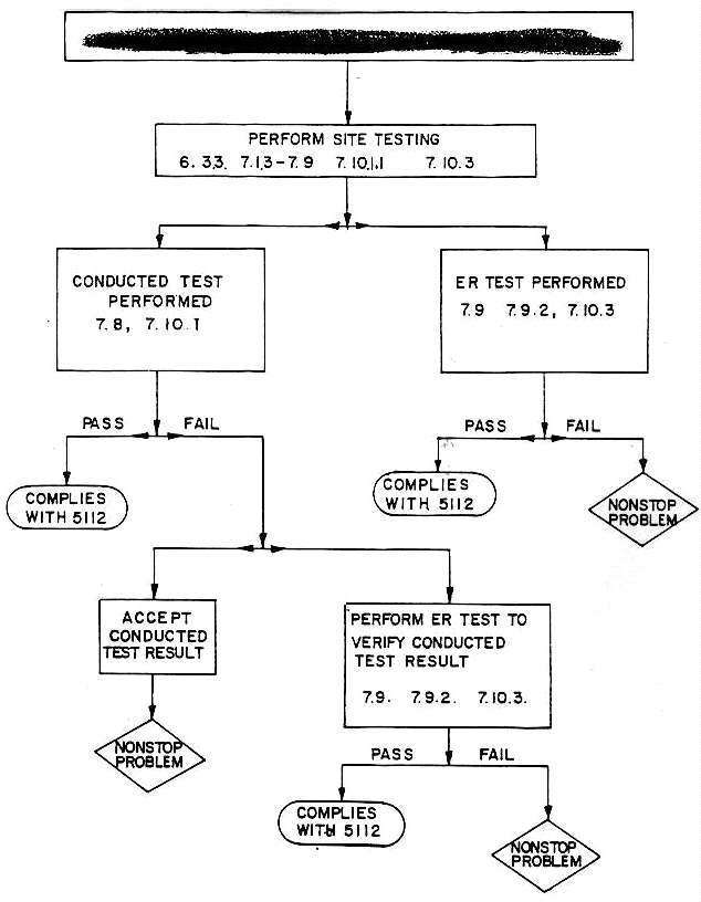
Table 2. - Testing Requirement Flow Diagram For
xxxxxxxxxxxxxxx
Operating At An Installation (U) (C).
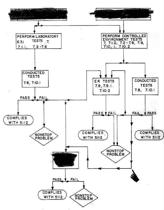
Table 3. Testing Requirement Flow Diagram For xxxxxxxxxxxxxxxxx (U) (C).
1 PAGE(S) WITHHELD FOR THE FOLLOWING REASON(S):
X (b)(1) of the FOIA_____ subparagraph 1.5(b) of E.O. 12958
X subparagraph 1.5(c) of E.O. 12958
_____ subparagraph 1.5(d) of E.O. 12958
X subparagraph 1.5(g) of E.O. 12958X (b)(3) of the FOIA
X 18 U.S.C. § 798
X 50 U.S.C. § 403-3(c)(6)
X 50 U.S.C. § 402 note (Public Law 86-36)_____ (b)(4) of the FOIA
_____ (b)(5) of the FOIA
_____ (b)(6) of the FOIA
_____ Not reasonably segregable for release
_____ Not Responsive to the request
LIST OF EFFECTIVE PAGES
| Blank pages are not indicated in the '"Page No." column if within a group of page numbers. However, all blank pages are accounted for by a notation such as "1-9/(1-10 blank)"" printed in the lower corner of the page on the reverse side of the blank page. A zero in the "Amend No." column indicates an original page. |
 Page No.	                            Amend No.

i/(ii blank)  - - - - - - - - - - - - - - -	3
iii - xi/(xii blank)  - - - - - - - - - - -	0
1 - 2 - - - - - - - - - - - - - - - - - - -	0
3 - 4 - - - - - - - - - - - - - - - - - - -	3
5 - 16  - - - - - - - - - - - - - - - - - -	0
17 - 18 - - - - - - - - - - - - - - - - - -	2
19 - 62 - - - - - - - - - - - - - - - - - -	0
63 - 64 - - - - - - - - - - - - - - - - - -	2
65 - 66 - - - - - - - - - - - - - - - - - -	1
67 - 68 - - - - - - - - - - - - - - - - - -	0
A-1 - A-3/(A-4 blank) - - - - - - - - - - -	0
B-1/(B-2 blank) - - - - - - - - - - - - - -	0
B-3/(B-4 blank) - - - - - - - - - - - - - -	3
B-5/(B-6 blank) - - - - - - - - - - - - - -	0
B-7 - B-9/(B-10 blank)  - - - - - - - - - -	2
B-11/(B-12 blank) - - - - - - - - - - - - -	0
B-13/(B-14 blank) - - - - - - - - - - - - -	2
B-15 - B-35/(B-36 blank)  - - - - - - - - -	0
B-37/(B-38 blank) - - - - - - - - - - - - -	1
B-39/(B-40 blank) - - - - - - - - - - - - -	0
B-41 - B-43/(B-44 blank) - - - - - - - - -	2
B-45/(B-46 blank) - - - - - - - - - - - - -	3
B-47/(B-48 blank) - - - - - - - - - - - - -	0
B-49 - B-51/(B-52 blank)  - - - - - - - - -	2
B-53 - B-57/(B-58 blank)  - - - - - - - - -	0
B-59/(B-60 blank) - - - - - - - - - - - - -	2
B-61/(B-62 blank) - - - - - - - - - - - - -	3
B-63 - B-83/(B-84 blank)  - - - - - - - - -	0
B-85/(B-86 blank) - - - - - - - - - - - - -	1
B-87/(B-88 blank) - - - -- - - - - - - - - -	0
B-89/(B-90 blank) - - - - - - - - - - - - -	3
[Back Cover.]
(Reverse Blank)
Transcription and HTML by Cryptome.