31 December 2000
Source: Hardcopy from the National Security Agency in response to an
appeal of an earlier FOIA
request for TEMPEST-related documents. See NSA letter:
nsa-foia-app2.htm
which released:
Three complete documents:
NSTISSAM TEMPEST/2-95, 12 December 1995, (FOUO) Red/Black Installation GuidanceSpecification NSA No. 94-106, 24 October 1994, (
FOUO) Specification for Shielded EnclosuresSpecification NSA No. 89-02, TBD, [No date], (
FOUO) Specification for Shielded Enclosures [This document is almost identical to NSA No. 94-106 which appears to have superceded it, so it will not be transcribed.]
Five partial documents with portions of text redacted:
NACSIM 5000, February 1982 (Confidential), Tempest Fundamentals [This document.]Appendix A, NACSIM 5000, Glossary, 31 March 1982 (
Confidential) [This is a duplicate of one in NACSIM 5000 above, so it will not be transcribed.]NSTISSI No. 7000, 29 September 1993 (
Confidential), Tempest Countermeasures for FacilitiesNSA/CSS 90-5 (
Secret), 7 June 1991, Tempest Security Requirements for NSA/CSS Contractors Processing Sensitive Compartmented Information (SCI)NACSEM 5112 (RP-4), April 1975, Reprint July 1987 (
Secret), NONSTOP Evaluation Techniques
The last two are in preparation for publication on Cryptome.
For comprehensive TEMPEST information see: http://www.eskimo.com/~joelm/tempest.html
xxxxxxx indicates redacted material.
[62 pages: Letter of Promulgation, TOC and Introduction marked UNCLASSIFIED;
other pages marked CONFIDENTIAL.]
NATIONAL SECURITY AGENCY
FORT GEORGE G. MEADE, MARYLAND 20755
NACSIM 5000
TEMPEST FUNDAMENTALS (U)
LETTER OF PROMULGATION
1. This publication was prepared by the National Communications Security Committee's Subcommittee on Compromising Emanations.
2. Consult List of Effective Pages and verify the presence of each page. This publication will become effective upon receipt and supersedes NAG-8A/TSEC which should be destroyed.
3. This publication shall not be further disseminated nor reproduced in its entirety without prior specific approval of the Director, National Security Agency. No classified part of this publication shall be reproduced or utilized by non-U.S. Government personnel, except as required when performing U.S. Government contracts. Extracts of unclassified information contained in this publication qualify for the marking "FOR OFFICIAL USE ONLY" and shall be treated and marked accordingly. Authorized U.S. Government personnel shall obtain copies of this publication through their SCOCE representative. Authorized contractor personnel shall request copies through their U.S. Government Contracting Officer.
4. During normal warking hours, extracts marked "FOR OFFICIAL USE ONLY" (FOUO) shall not be left unattended in work areas accessible to unofficial personnel. but shall be placed in an out-of-sight location. At the close of business, FOUO material shall be stored to preclude unauthorized access. Filing such material in unlocked files, desks or similar containers is adequate when normal U.S. Government or Government-contractor internal building security is provided during nonduty hours. When such internal security control is not exercised, locked buildings or rooms normally provide adequate after hours protection. If such protection is not considered adequate, FOUO material shall be stored in locked receptacles such as file cabinets, desks, or bookcases.
5. This publication is distributed to U.S. Government departments and agencies charged with the responsibility for ensuring that compromising emanations from, equipment and systems used to process national security information are not exploited to the detriment of the national security of the United States. This publication may be released to authorized qualified contractors consistent with the U.S. Government regulations and policy. and provided that adequate security facilities are available to safeguard classified information in accordance with the provisions of DoD 5220.22-M. the Industrial Security Manual for Safeguarding Classified Information and the COMSEC Supplement thereto. Authorization for such releases is the responsibility of the U.S. Government or Agency sponsoring the release.
6. THIS PUBLICATION OR THE INFORMATION IT CONTAINS MAY NOT BE RELEASED TO FOREIGN NATIONALS WITHOUT PRIOR SPECIFIC APPROVAL FROM THE DIRECTOR, NATIONAL SECURITY AGENCY. ALL APPROVALS WILL IDENTIFY THE SPECIFIC INFORMATION OR COPIES OF THIS PUBLICATION AUTHORIZED FOR RELEASE TO SPECIFIC FOREIGN HOLDERS. ALL REQUESTS FOR ADDITIONAL ISSUANCES MUST RECEIVE PRIOR SPECIFIC APPROVAL FROM THE DIRECTOR, NATIONAL SECURITY AGENCY.
1 February 1982
[Signature]
HOWARD E. ROSENBLUM
Deputy Director, NSA
for
Communications Security
THIS PAGE IS INTENTIONALLY BLANK
RECORD OF AMENDMENTS
[Blank form.]
RECORD OF PAGE CHECKS
[Blank form.]
THIS PAGE IS INTENTIONALLY BLANK
TABLE OF CONTENTS (U) (C)
General
Purpose
Comments and Recommendations
CHAPTER 1
INTRODUCTION TO TEMPEST (U)
Background
Electromagnetic Field Composition
Sources of TEMPEST Signals
Functional Sources
Incidental Sources
Types of TEMPEST Signals
RED Baseband Signals
Modulated Spurious Carriers
Impulsive Emanations
Other Types of Emanations
Propagation of TEMPEST Signals
Electromagnetic Radiation
Line Conduction
Fortuitous Conduction
xxxxxxxxxxxxx (C)
Acoustics
CHAPTER 2
NATIONAL TEMPEST PROGRAM (U)
TEMPEST Threat
National Policy
Heads of Organizations
Director, National Security Agency
SCOCE
National Program
Subcommittee on Compromising Emanations
TEMPEST Technical Special Committee
TEMPEST Qualification Special Committee
Industrial TEMPEST Program
TEMPEST Information Center
National TEMPEST Publications
National Communications Security Information Memoranda
National Communications Security Instructions
Test Selection
TEMPEST Tests
Source Identification
Test Types
Test Plan
Test Procedures
TEMPEST Instrumentation
Test Messages
Measurement Units
Emanation Identification
Compromising Emanations Associated with Serial RED Signals
Compromising Emanations Associated with Parallel (RZ) RED Signals
CHAPTER 4
PREVENTION OF TEMPEST EMANATIONS (U)
Introduction
Causes of TEMPEST Emanations
Equipment Design
Preventive Measures
Functions and Format Selections
Signal Power Levels
Signal Spectrum Limits
Circuit Arrangement and Layout
Return Path Layout
Stage Decoupling
Shielding
Filtering
Isolation
Facility Design
CHAPTER 5
TEMPEST REQUIREMENTS (U)
Determination of Requirements
TEMPEST Data
TEMPEST Support
CHAPTER 6
TEMPEST DOCUMENTATION (U)
General
Organizational Level Documents
Introduction
APPENDIX B
CLASSIFICATION OF COMPROMISING EMANATIONS INFORMATION
(U)
General
Scope
Rationale
Marking
Foreign Release
Specific Guidelines
TEMPEST Classification Chart Outline
TEMPEST Classification Chart
LIST OF EFFECTIVE PAGES
LIST OF ILLUSTRATIONS (U)
1-1 Pulse/Emanation Relationships
1-2 Electromagnetic Field Composition
1-3 Time and Frequency Domain of Compron-using Modulating Signals and Modulated Carriers
1-4 Time and Frequency Domain of RED Digital Data and Correlated Impulsive Emanations
1-5 Amplitude-Modulated Carrier
1-6 Sound Wave Transmission
2-1 SCOCE Organizational Chart
3-1 Likeness of an Equipment Under Test
3-2 TEMPEST Test Instrumentation
3-3 Detected Emanation in Baseband Form Correlated to Analog Monitor Signal
3-4 Detected Emanation in Baseband Form Correlated to Digital Monitor Signal
3-5 Detected Impulsive Emanation Correlated to Both Transitions of Digital Monitor Signal (Without Demodulator)
3-6 Detected Impulsive Emanations Correlated to Both Transitions of Digital Monitor Signal (With Demodulator)
3-7 Detected Impulsive Emanation Correlated to Mark-to-Space Transitions of Digital Monitor Signal
3-8 Detected Impulsive Emanation Correlated to Space-to-Mark Transitions
of Digital Monitor Signal
LIST OF TABLES (U)
2-1 SCOCE Members/Observers
3-1 TEMPEST Tests
3-2 Potential Sources
3-3 Test Categories
3-4 TEMPEST Hazard Levels of Emanations Resulting from (RZ) Parallel Data Handling/Transfer
5-1 TEMPEST Data
5-2 References to TEMPEST Data
6-1 National Level Publications
1. (U) General. - This handbook provides an introduction to t be TEMPEST phenomenon which includes, among other observable facts, the suppression of compromising emanations and the different types of TEMPEST signals. Although compromising emanations are detectable as both electromagnetic and acoustic signals (both of which are defined herein), this publication is primarily oriented toward the identification, suppression and containment of electromagnetic emanations. More information on the acoustic phenomenon is available in the effective edition of NACSEM 5103.*
____________________
* For long title of this publication please see Table 6-1.
2. (U) Purpose. - The purposes of this handbook are to describe the TEMPEST phenomena and serve as guide to related TEMPEST information. This handbook should be used primarily by nontechnical persons who have an interest in TEMPEST. It can also be used as a refresher by TEMPEST engineers and technicians.
3. (U) Comments and Recommendations. - Revisions to this publication will be made as appropriate. Comments, corrections and recommendations on its contents are encouraged. Government organizations should submit their comments to their appropriate department or agency authority. Department or agency authorities may submit their comments to:
Director
National Security Agency
ATTN: Chairman, SCOCE, 564
Ft. George G. Meade, Maryland 20755
Contractors should submit their comments to their contracting goverriment organization. Industrial firms which have no appropriate government contract may submit their comments directly to the above address. A comment sheet is provided in the back of the book for that purpose. When submitting comments. it is suggested that this form be reproduced or a similar format be used.
THIS PAGE IS INTENTIONALLY BLANK
1-1. (C) Background (U). - TEMPEST is a short name
referring to investigations and studies of compromising emanations (CE).
Compromising emanations are defined as unintentiorial intelligence-bearing
signals which, if intercepted and analyzed, disclose the national security
information transmitted, received, handled or otherwise processed by any
information-processing equipment. Compromising emanations consist of electrical
or acoustical energy unintentionally emitted by any of a great number of
sources within equipment/systems which process national security information.
This energy may relate to the original message, or information being processed,
in such a way that it can lead to recovery of the plaintext. Laboratory and
field tests have established that such CE can be propagated through space
and along nearby conductors. The interception/propagation ranges and analysis
of such emanations are affected by a variety of factors, e.g., the functional
design of the information processing equipment; system/equipment installation;
and, environmental conditions related to physical security and ambient noise.
The term "compromising emanations" rather than "radiation" is used because
the compromising signals can, and do, exist in several forms such as magnetic
and/or electric field radiation, line conduction, (signal and power),
xxxxxxxxxxxxxxx, or acoustic emissions. More specifically, the emanations
occur as:
a. (U) Electromagnetic fields set free by elements of the plaintext processing equipment or its associatcd conductors.b. (
C) Text-related signals coupled to cipher, power, signal, control or other BLACK lines through (1) common circuit elements such as grounds and power supplies or (2) inductive and capacitive coupling.c. (
C) [Two lines redacted.]d. (
C) Propagation of sound waves from mechanical or electromechanical devices.e. (
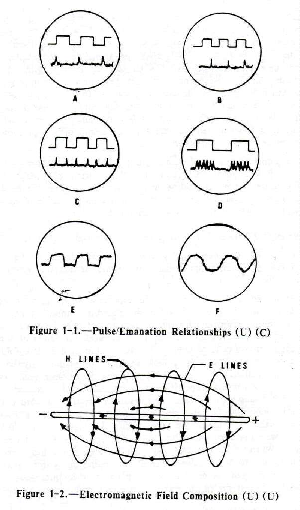
C) The forms in which compromising emanations might appear at an interception point are numerous. A few are illustrated in Figure 1-1. At A, the leading edges of the square wave result in the formation of clearly distinguishable pulses within the associated emanations. At B, the lagging edges have the same effect and at C changes are registered at both rise and fall times. Illustration D indicates how the level of emanations might vary directly with the level of the originating signals. E and F simply illustrate stray signals. Any one of these stray signals could in some way represent the original classified information -- perhaps by appearing repetitively at the same point or by being constantly above or below average levels. Many methods of converting such seemingly random pulses to meaningful data are available to the analystf. (U) The TEMPEST problem is not one which is confined to cryptographic devices; it is a system problem and is of concern for all equipment which process plaintext national security data.
1-2. (U) Electromagnetic Field Composition (U). - Some knowledge of electromagnetic field composition is necessary to understanding compromising emanations. More of these emanations are generated in electromagnetic field form than in any other. The fields are produced when current flows through a conductor, and are composed of an electric (E) field component and a magnetic (H) field component. The two are mutually dependent: no moving E field can exist without an associated H field. They radiate from a conductor roughly traveling at right angles to each other, (See Figure 1-2.) As the illustration suggests, the electric field is related to differences of potential along the conductor (here indicated by the plus and minus at the ends of the illustrated conductor segment). This electric field, then, is stronger in circuits where voltage, in relation to current, is high. (The higher the voltage the higher the amplitude of the electric field component.) The magnetic field emerges as an expanding circle around the conductor and is dependent more on current flow than on potential differences. Therefore, in relatively high current circuit operation this magnetic field component is dominant.
a. (C) [Seven lines redacted.]
b. (C) T he strongest and most numerous electromagnetic
emanations are generated by sharp-rising and current waveforms of short duration.
As the front of the wave becomes less sloped and closer to vertical (rise
time becomes faster), the force with which related bursts of electromagnetic
energy leave the source becomes greater (i.e., the emanations are of greater
amplitude). Also, faster rise times generate additional emanations -- harmonics
-- of progressively lower amplitudes from the same pulse source, These harmonics
are radiated fields which occur at some multiple of the frequency of the
originating signal and represent, in effect, a great many compromising signals.
These signals can be acquired not only by being correctly tuned to the
fundamental frequency, but also at any of the harmonic frequencies (so long
as the harmonics are of sufficient amplitude to be detected). At times, in
fact, harmonics are more useful than the fundamental, i.e., emanations at
the fundamental frequency are often lost among other signals of the same
frequency, whereas a harmonic might be more easily isolated.
c. (C) The electromagnetics problem, then, is this: Fields
of sufficient strength to be intercepted at a distance can be released from
a conductor when rapid current or voltage changes take place within the
conductor. The processing of national security information involves the
production of rapidly rising and falling signals. Therefore, our
information-processing system is capable of radiating fields which nullify
the concealment operation which the system is attempting to perform.
1-3. (C) Sources of TEMPEST Signals (U). - There
are two basic sources of such signals:
a. (U) Functional Sources. - Functional sources are those designed for the specific purpose of generating electromagnetic energy. Examples are switching transistors, oscillators. signal generators, synchronizers, line drivers, and line relays.
b. (C) Incidental Sources (U). - Incidental sources are
those which are not designed for the specific purpose of generating
electromagnetic energy. Examples are electromechanical switches and brush-type
motors. The sources of compromising emanations may include all electromechanical
and electronic equipment and systems used to process national security
information. In determining the extent of compromising emanations, and the
necessary countermeasures to be applied, equipment must be considered
individually and as components of a system. Any circuit processing national
security information may be a source of compromising emanations, and
installations using individually suppressed equipments and systems could
be sources of compromising emanations unless proper installation and maintenance
procedures are utilized. The generation of some types of CE has been increased
as a result of the trend toward compactness which has forced conductors,
components and circuits into such proximity that coupling between secure
and nonsecure elements is unavoidable. The use of the same circuitry for
more than one function, and the same circuit board for two or more operations,
has also created problems. The use of faster data rates has increased the
harmonic content. When CE are radiated, they might leave the Controlled Space
(CS) along signal, phone or powerlines, through conductive structures such
as steel beams and water pipes, or as direct radiation from the source. The
signals need not be of great magnitude to be compromising because receiving
instruments with which they can be intercepted can make use of even a small
amount of energy,
1-4. (C) Types of TEMPEST Signals. - In practice,
the more common types of CE are attenuated RED baseband signals, spurious
carriers modulated by RED baseband signals, and impulsive emanations.
a. (C) RED Baseband Signals (U). - The most easily recognized
CE is the RED baseband signal in attenuated but otherwise unaltered form,
since it is essentially identical to the RED baseband signal itself. This
emanation can be introduced into electrical conductors connected to circuits
(within an EUT) which have an impedance or a power source in common with
circuits processing RED baseband signals. It can be introduced into an escape
medium by capacitive or inductive coupling, and especially by radiation with
RED baseband signals of higher frequencies or data rates.
b. (C) Modulated Spurious Carriers (U). - This type of CE
is generated as the modulation of a carrier by RED data. The carrier may
be a parasitic oscillation generated in the equipment, i.e., the chopper
frequency of a power supply, etc. The carrier is usually amplitude or
angle-modulated by the basic RED data signal. or a signal related to the
basic RED data signal, which is then radiated into space or coupled into
EUT external conductors. See Figure 1-3 for time and frequency domain
representations.
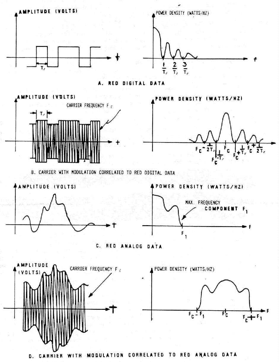
Figure 1-3. - Time and Frequency Domain of Compromising Modulating
Signals
and Modulated Carriers (U)
c. (U) Impulsive Emanations. - Impulsive emanations are quite common in EUT's processing digital signal, and are caused by very fast mark-to-space and space-to-mark transitions of digital signals. Impulsive emanations can be radiated into space or coupled into EUT external conductors. See Figure 1-4 for the time and frequency domain representations.

Figure 1-4. -Time and Frequency Domain of RED Digital Data
and Correlated Impulsive Emanations (U) (C)
d. (U) Other Types of Emanations. - Most CE resemble one of the types mentioned thus far. There are, however, other possible types of CE which are caused by various linear and nonlinear operations occurring in information-processing equipments and systems. Such CE cannot easily be categorized. In practice, these emanations often exhibit features which can frequently be related to one of the three types discussed.
1-5. (C) Propagation of TEMPEST Signals (U). - There
are four basic means by which compromising emanations may be propagated.
They are: electromagnetic radiation; conduction; modulation of an intended
signal; and acoustics. A brief explanation of each follows.
a. (C) Electromagnetic Radiation (U). - Whenever a RED signal
is generated or processed in an equipment, an electric, magnetic or
electromagnetic field is generated. If this electromagnetic field is permitted
to exist outside of an equipment, a twofold problem is created; first the
electromagnetic field may be detected outside the Controlled Space (CS);
second the electromagnetic field may couple onto BLACK lines connected to
or located near the equipments, which exit the CS of the installation.
b. (C) Line Conduction. - Line Conduction is defined as
the emanations produced on any external or interface line of an equipment,
which, in any way, alters the signal on the external or interface lines.
The external lines include signal lines, control and indicator lines, and
a.c. and d.c. powerlines.
c. (C) Fortuitous Conduction. - Emanations in the form of
signals propagated along any unintended conductor such as pipes, beams, wires,
cables, conduits, ducts, etc.
d. (C) [Six lines redacted.]
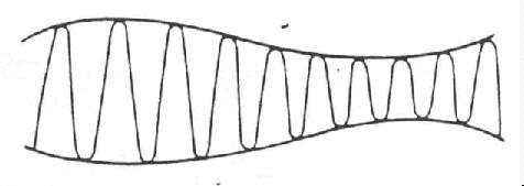
Figure 1-5. - Amplitude-Modulated Carrier (U) (U)
e. (C) Acoustics (U) - Characteristically plaintext processing
systems are primarily electrical in function. However, other sources of CE
exist where mechanical operations occur and sound is produced. Keyboards,
printers, relays -- these produce sound. and consequently can be sources
of compromise.
(1) (U) Transduction is the process which relates acoustics (the science of sound) to electronics. A transducer is a device which converts one form of energy to another. When two bodies strike, a sound wave, effectively the movement of mechanical energy, is set into motion. Transduction occurs when some instrument transforms this mechanical energy into electrical energy. Microphones are transducers; so are the dynamic elements in the ear and mouthpieces of a telephone; an accelerometer (common vibration detector) is also a transducer.(2) (U) For our purposes. the definition of sound is not affected by the limitations of the human ear. A sound exists when mechanical energy is propagated through an elastic medium (e.g., air) causing a displacement of particles which can be detected by a person or an instrument. The elasticity of air is demonstrated by the property which enables it to pull a displaced particle back to its original position. Figure 1-6 illustrates the effects of a vibrating wall on surrounding air particles. (Motion of the wall segment shown is, of course, exaggerated. Movement is usually imperceptible.) In its forward movement (A), the wall compresses the nearest air particles. These are given momentum and compress adjacent particles which collide with others, and so on. The original motion is capable of carrying particle displacement waves (sound waves) a long distance. When the wall reverses direction, the particles nearest the wall are drawn back with it (B), and because of this change in density a backward acceleration begins. The initial forward movement continues, however, as a wave of displaced particles; the backward motion is simply that of the particles returning to their original positions. When the wall passes (C), then returns to its starting point (D), a single sound wave has been propagated and each additional vibration transmits another wave (E).
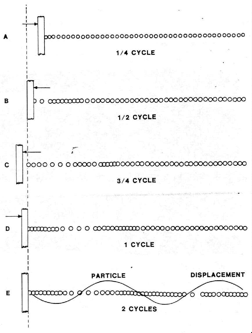
Figure 1-6. - Sound Wave Transmission (U) (U)
(3) (
C) Just as vibrations cause sound waves, sound waves can also cause vibrations. Therefore, a wall such as the one illustrated could be set into motion by waves emanating from a mechanical plaintext processing device; these waves would be reproduced on the opposite side of the wall and transmitted into space.(4) (
C) Transmission through space is only one of the ways in which accoustical energy can be transported beyond secure bmits. It can also travel along fortuitous conductors and telephone lines. In the latter case, transduction through either the transmit or receive element of a handset or through a telephone ringing element may occur and the handset need not be off the cradle in order for its elements to be activated.
2-1. (C) TEMPEST Threat (U). - TEMPEST threat assessments
have been conducted by the Subcommittee on Compromising Emanations. In every
instance, emphasis was placed on an opposition's or potential opposition's
knowledge of the techniques required to exploit compromising emanations and
what they do to protect themselves against such exploitation.
a. (C) [4 lines redacted.]
b. (C) [7 lines redacted.]
c. (C) The exploitation of CE is primarily a passive effort;
that is [3 lines redacted.]
d. (C) [4 lines redacted.]
e. (C) [4 lines redacted.]
2-2. (C) National Policy (U). - It is the intent
of the national policy for the control of compromising emanations to prevent
the loss of national security information through the exploitation of TEMPEST
signals by hostile forces. As described above, the threat is real and if
TEMPEST signals are allowed to exist, our enemies will make use of them to
compromise the national security data being processed. As such, the national
policy objective is to assure that each U.S. Government organization takes
the steps necessary to prevent the loss of national security information
through the interception of unintentional emanations. To that end,
responsibilities have been assigned as follows:
a. (U) Heads of Organizations:
(1) Planning, programming and funding for implementing and managing compromising emanations control programs.(2) Promulgating directives, standards, and instructions to implement this pohcy within their organizations.
(3) Coordinating this program through the Subcommittee on Compromising Emanations (SCOCE).
(4) Providing copies of TEMPEST reports to the SCOCE TEMPEST Information Center.
b. (U) Director, National Security Agency. - In addition to the responsibilities listed in paragraph 2-2a, the DIRNSA is responsible for:
(1) Providing all aspects of TEMPEST support as it relates to cryptographic devices.(2) Providing consultation, advisory information and planning assistance to other organizations.
(3) Operating for members of SCOCE a national TEMPEST Information Center.
(4) Providing guidance on the classification of communications security information pertaining to CE and its release to contractors and foreign nations.
(5) Conducting a SCOCE program to encourage industry to voluntarily develop TEMPEST suppressed equipment.
(6) Publishing periodically, for members of SCOCE, a preferred products list (PPL) of TEMPEST accredited equipments.
c. (U) SCOCE. - Acting as a forum for the exchange of information on CE among interested U.S. Government departments and agencies.
2-3. (C) National Program (U). - The national policy
designates that the heads of all organizations are responsible for addressing
the TEMPEST problem. However, to ensure that all information on the TEMPEST
program is exchanged on a timely basis, and that problems and policy which
will effect all organizations are provided the appropriate forum for discussion,
a national level TEMPEST organization has been established. During the late
1950's, the United States Communication Security Board was organized to address
the security of U.S. communications systems. However, in 1978, this organization
was dissolved by Presidential Directive PD/NSC-24 and subsequently replaced
by the National Communications Security Committee (NCSC). This new committee
is responsible for the conduct of COMSEC activities within the U. S. Government.
a. (U) Subcommittee on Compromising Emanations. - SCOCE was formally established in December 1960 and continues today as a Subcommittee of the NCSC. SCOCE provides TEMPEST guidance to government departments and agencies, and to private industry. Figure 2-1 and Table 2-1 show the SCOCE organization and SCOCE member and observer organizations. The SCOCE is responsible for:
(1) Recommending national policy guidance for NCSC approval.(2) Acting as the control authority to ensure that the national policy objectives are observed.
(3) Providing the forum for the exchange of TEMPEST information.
(4) Providing liaison with non-NCSC government organizations concerned with TEMPEST problems.
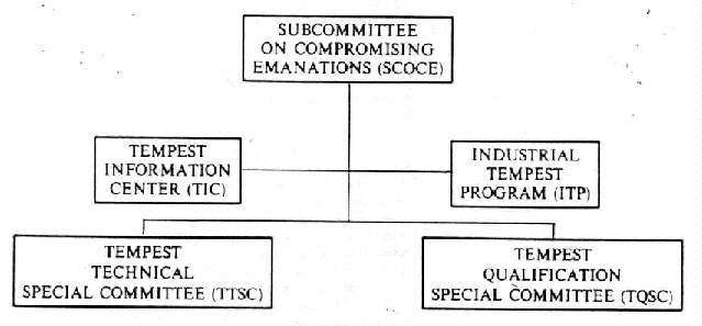
Figure 2-1.-SCOCE Organizational Chart (U) (U)
b. (U) TEMPEST Technical Special Committee. - The TTSC was established in 1975. The special committee is responsible for technical tasks approved by the SCOCE. Its tasks are:
(1) Coordinating TEMPEST R&D efforts.(2) Exchanging information on TEMPEST laboratory testing and R&D studies.
(3) Developing TEMPEST technical documentation.
(4) Coordinating all automated TEMPEST testing and analysis efforts.
(5) Conducting TEMPEST technical symposiums.
(6) Coordinating and developing TEMPEST training courses.
c. (U) TEMPEST Qualification Special Committee. - The TQSC was established in 1978. The primary objectives are the TEMPEST accreditation of commercial equipments and the recommendation to SCOCE of items to be included on a TEMPEST Preferred Products List. This special committee's members review TEMPEST test plans, which are submitted by industry, to determine if the proposed testing will meet all requirements of the effective edition of NACSIM 5100.* If the test plan is accepted, the company is notified and can commence testing. The special committee reserves the right to witness any portion of the testing. After completion of the testing, a final, comprehensive report is submitted. If the TQSC accepts the report, the equipment is accredited and it is recommended to SCOCE that it be included on the PPL., The special committee can revoke accreditation if subsequent data reveal that any approved equipment has an unacceptable TEMPEST profile.
____________________
* For long title of this publication please see Table 6-1.
TABLE 2-1
SCOCE MEMBERS/OBSERVERS (U) ( Chairman National Security Agency Members
Department of State Observers
Office of the Joint Chiefs of Staff |
d. (U) Industrial TEMPEST Program. - One of the responsibilities of the SCOCE
is to motivate private industry to develop and offer TEMPEST suppressed
equipments and provide for the exchange of TEMPEST information. The ITP was
established to support commercial firms who do not have a current TEMPEST
related contract with the government and who wish to voluntarily design.,
produce, or test TEMPEST secure equipment or products. The program is run
for SCOCE by the National Security Agency. Once a firm demonstrates that
their TEMPEST efforts are beneficial to the government, the NSA effects a
no-cost contract and a need-to-know for TEMPEST data. Subsequently, the NSA
provides TEMPEST information to achieve the program objectives.
e. (U) TEMPEST Information Center. - The SCOCE has a national TEMPEST Information Center to which all agencies and departments performing TEMPEST testing can send copies of their final test reports for archival retention. The NSA operates the TIC for SCOCE. The purposes of the TIC are to furnish TEMPEST documentation to requesting members and observers of the SCOCE and to provide a research service and the loan of hard copies and/or microfiche copies of test reports. To facilitate the distribution of this information the TIC forwards to all SCOCE activities a monthly TEMPEST Accession List which reproduces the report data received by the TIC for that rnonth. Through these summaries, a TIC user can determine which reports are required to obtain needed TEMPEST information. Government personnel requiring TEMPEST data should make their requests through their SCOCE representative. Contractors should request data through their goverment contracting officer.
2-4. (C) National TEMPEST Publications. - Generally,
national TEMPEST publications are advisory and informative, not directive
as is the national policy. The publications which pertain to CE are issued
through the NCSC national COMSEC-issuance system and may be NACSIMs or NACSIs.
The TEMPEST NACSIMs are numbered in the five thousand series. The three groups
within that numbered series are: 5000 through 5099, indicate general information
and have blue covers; 5100 through 5199 indicate technicallyy valid testing
data and have white covers; 5200 through 5299 indicate design criteria and
have yellow covers. The TEMPEST NACSIs are also numbered in the five thousand
series and have white covers. The NSA prints and distributes these publications
to interested government departments and agencies and qualified members of
the Industrial TEMPEST program. Government personnel may obtain copies of
pubhcations through their SCOCE representative and contractors from their
government contracting officer. The following subparagraphs describe the
types of publication utilized to disseminate TEMPEST guidance and information.
a. (U) National Communications Security Information Memoranda. - These contain information of general interest or application pertaining to technical or procedural aspects of COMSEC. NACSIMs are printed and distributed by the NSA.
b. (C) National Communications Security Instructions. -
These provide instruction and establish technical criteria to be implemented
by the departments and agencies on specific COMSEC matters. NACSIs are printed
and distributed by the NSA and provide legal guidelines, restrictions, and
procedures promulgated by DoD and approved by the Attorney General that are
applicable to the conduct of COMSEC activities.
3-1. (C) Test Selection. - TEMPEST tests are performed
to prove that all or a part of communications or information handling systems
which are to process national security information do, in fact. provide emission
security. An equipment or system tested is called an equipment under test
(EUT). An EUT can be visualized as an input/output box which receives an
input signal and produces an output signal (see Figure 3-1).

Figure 3-1. - Likeness of an Equipment Under Test (U) (U)
In most cases, only EUT input and/or output conductors carry the intentional RED signals; all other conductors usually carry signals devoid of classified data. Because of design weaknesses, poor component quality or location, improper wiring layout, and inadequate shielding by the chassis cabinet, some unintentional signals may be generated in an EUT and emitted through space or on external conductors. Such unintentional signals are the object of detection and measurement during TEMPEST tests, and of particular interest are those signals which may be similar to the RED signals because they are compromising emanations (CE).
a. (C) TEMPEST Tests. - Table 3-1 lists TEMPEST tests required
by NACSIM 5100A*; it is based on emanation source and detection system and
escape medium. On the basis of emanation source, TEMPEST tests are either
pulse-width or transition-time related. On the basis of detection system,
TEMPEST tests are either nontunable or tunable. Nontunable tests detect and
measure RED baseband emanations or lower frequency impulsive emanations.
They employ detection systems containing no demodulators and provide frequency
coverage selectivity in one or more discrete increments. Tunable tests detect
and measure spurious carriers modulated by RED baseband signals or higher
frequency impulsive emanations and employ detection systems which demodulate
detected emanations and are capable of continuously variable frequency coverage
within given frequency bounds. On the basis of escape medium, TEMPEST tests
are classified as electric radiation, magnetic radiation, or conduction (signal,
control, powerlines) [one line redacted].
____________________
* For long title of this publication please see Table 6-1.
TABLE 3-1
TEMPEST TESTS (U) ( |
||
Emanation Source |
Detection System |
Escape Medium |
| Pulse Width | Nontunable Tunable |
Electric Radiation (ER) |
| Transition Time | Nontunable Tunable |
|
| Pulse Width | Nontunable Tunable |
Magnetic Radiation (MR) |
| Transition Time | Nontunable Tunable |
|
| Pulse Width | Nontunable Tunable |
Conduction (C) |
| Transition Time | Nontunable Tunable |
|
| xxxxxxxxxxxxx xxxxxxxxxxxxx |
Nontunable |
xxxxxxxxxxxxxx |
| xxxxxxxxxxxxx | Nontunable |
xxxxxxxx |
b. (C) Source Identification. - Prior to developing the
TEMPEST test plan it is necessary to determine all potential sources of CE
within the EUT. This is accomplished by developing a data flow diagram which
depicts the RED signal(s) as they proceed through the EUT from input to output.
Each point at which the data is processed (i.e., changed in format, buffered,
amplified, stored, displayed, printed, etc.) is a potential TEMPEST emanation
source. Once the flow diagram is completed, a table is developed to list
all potential sources and their pertinent parameters. (See Table 3-2.) Monitor
points are identified for each signal source against which any detected
emanations can be compared to determine correlation/compromise. To ensure
a complete TEMPEST investigation of all EUT circuits and signal paths, tests
must be performed with an EUT in each of its operational modes. If, for example,
an EUT is part of a half-duplex communications system and includes both a
transmitter and receiver, a complete series of TEMPEST tests is required
with the EUT operating in receive and transmit mode separately. Similarly,
a digital disc system would have to be tested in both the read and write
modes.
TABLE 3-2
POTENTIAL SOURCES (U) ( |
||||
Source |
Format |
Min. |
Tans. Time |
Code |
| Data Input | Serial | 2400 baud/417µs | 20.9µs | ASCII Odd Parity |
| Serial-Parallel Converter | Serial In | 2400 baud/417µs | 20.9µs | ASCII Odd Parity |
| Serial-Parallel Converter | Parallel Out | 100 K Byte/sec/1µs | 10ns | ASCII Odd Parity |
| Data Output | Parallel | 9600 baud/104µs | 1.4µs | ASCII Odd Parity |
c. (C) Test Types (U).
(1) (U) Electric radiation tests are performed to detect and measure emanations escaping from an EUT in the form of E-fields.(2) (U) Magnetic radiation tests are performed to detect and measure emanations escaping from an EUT in the form of H-fields.
(3) (U) Conduction tests are performed to detect and measure emanations escaping from an EUT as voltage and current on conductors (including returns and grounds) interfacing an EUT with other equipments and power sources.
(4) (
C) [2 lines redacted.]
d. (U) Test Plan. - Based on the data gathered concerning the EUT, a test plan is developed which identifies (1) all EUT potential sources; (2) all EUT operational modes; (3) appropriate test categories (see Table 3-3); (4) test media to be examined; (5) tuning ranges and bandwidths to be used in the selection of ! detection system; and (6) monitor points for each potential source. See the effective edition of NACSIM 5100* for specific details.
____________________
* For long title of this publication please see Table 6-1.
TABLE 3-3
TEST CATEGORIES (U) ( |
||
Category |
R = Rd (b/s or Hz) |
Transition Times |
x |
xxxxxxxxxxxx |
xxxxxxxxxxxx |
| *Rd = 1/Pulse Width (minimum). Rt = 0.1/Tt. ** This includes analog speech. |
||
3-2 (C) Test Procedures (U). - Once the basic test
plan is developed, the data can be utilized to identify the specific test
instrumentation and procedures required to execute the TEMPEST test of the
EUT.
a. (U) TEMPEST Instrumentation. - Figure 3-2 is a block diagram of a typical TEMPEST test instrumentation setup. The setup includes such devices and instruments as transducers, detectors, emanation analysis instruments, substitution signal generators and ancillary equipment.
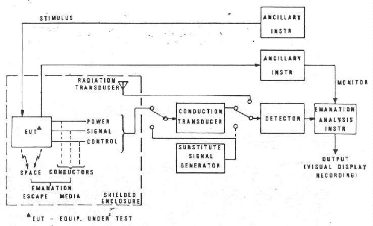
Figure 3-2. - TEMPEST Test Instrumentation (U) (U)
(1) (C) Transducer (U). - The transducer is a device which
interfaces emanation escape media with the detector. In radiated tests, these
transducers are E-field antennas (ER tests), either active or passive, mainetic
loops (MR tests) or microphones (acoustical tests). In conducted tests, a
transducer can be a coupling capacitor, a filter, a transformer, a powerline
stabilization network (PLC tests), a voltage probe, a current probe, or a
high impedance preamplifier if the line under test cannot be loaded with
the input impedance of the detector, which usually is 50 ohms.
(2) (U) Detector. - The detector is a low-noise amplifier with appropriate filters to establish required bandwidths in nontunable tests and a superheterodyne receiver in tunable tests. Since the frequency range of tunable TEMPEST tests is quite wide, several receivers normally are required to cover the entire test frequency range and to provide the required selection of bandwidths.
(3) (C) Emanation Analysis (U). - Emanation analysis instruments
allow identification of the information carrying characteristics of detected
emanations. They include oscilloscopes, raster generators, oscilloscope cameras.
paper charts, and magnetic tape/disc recorders. Oscilloscopes are used throughout
all tests. Detected emanation and RED monitor signals are displayed
simultaneously on an oscilloscope screen for comparison. Using the oscilloscope
alone, A-scope display (amplitude versus time) of both signals is used. Raster
generators allow the detected emanation to be displayed in a raster-type
form on the oscilloscope screen. Cameras and recorders are used when the
compromising nature of detected signals cannot be established from the
oscilloscope display. They also are useful to provide photographs/records
- for inclusion in test reports.
(4) (U) Calibration. - Emanation levels are measured by substituting calibrated signals from a substitution signal generator for the emanation to be measured; this technique is called "substitution measurement". The peak-to-peak amplitude of a displayed emanation is matched with a substitution signal inserted at the detector input or at the transducer calibration input. The emanation level is then computed from the level of the inserted substitution signal and any applicable transducer transfer characteristic applied (antenna factor or correction factor, such as attenuation, gain, etc.). Commonly used substitution sources include impulse and sine wave generators. When impulse generators are used, the signal levels in dBµV/MHz are converted to dBµV by applying a bandwidth correction factor to the impulsive signal level.
(b) (C) Test Messages (U). - The test message utilized to
exercise the EUT is a key element in the identification of CE. The message
must be designed so as to highlight the expected emanations parameters and
provide a pattern which can easily be interpreted. A sufficient number of
different characters and/or symbols must be included in the test message
to enable the information content to be properly evaluated. Although the
following subparagraphs indicate the typical types of test messages used
for TEMPEST tests, the test engineers must have complete freedom to change
the message at any time to enable accurate evaluation of potential CE and
calculation of the required measure of information content.
(1) (C) Serial (U). - Alternating groups of characters (20 of each) whose bits are juxtapositioned so that both aurally and visually the emanations are easily identified.(2) xxxxxxxxxxxxx Return to Zero (RZ) (U). - Alternating groups of characters are those with the [3 lines redacted].
(3) xxxxxxxxxxxxx Nonreturn to Zero (NRZ) (u). - the same typ of rationale as for (2) above prevails except [1 line redacted].
(4) (U) The above examples are far from all inclusive and are but an indication of how a test message can be constructed. Care must be taken to ensure that whichever test message is utilized, it does, in fact, produce the desired effect (change of bit pattern, change of number of bits, etc.) on the circuit under test so that any potential CE are highlighted.
c. (C) Measurement Units (U). - Emanation measurement units,
in dB, apphcable to common TEMPEST test are as follows:
Conduction: dBµV rms
ER: dBµV/m rms
MR: dBµA/m rms
Acoustical: dBmµbars/Hz
(1) (C) [2 lines redacted.](2) (
C) [2 lines redacted.]
3-3 (C) Emanation Identification (U). - [25 lines
redacted.]
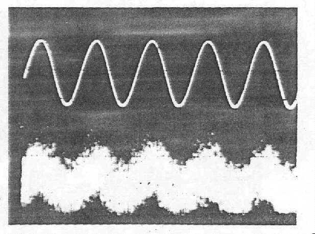
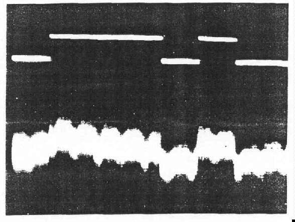
a. (C) Compromising Emanations Associated with Serial RED
Signals (U). - A partial listing (with sample waveform photographs) of correlated
emanations which compromise national security information carried by serial
monitor signals follows. In the sample photographs, the monitor signal waveform
is displayed above that of the detected emanation.
(1) (C) [6 lines redacted.]
a. A-scope display
[b. Emanation display redacted.]
Figure 3-3.-Detected Emanation in Baseband Form Correlated to Analog Monitor
Signal (U) (C)
a. A-scope display
[b. Emanation display redacted.]
Figure 3-4.-Detected Emanation in Baseband Form Correlated to Digital Monitor Signal (U) (C)
TABLE 3-4
[Table title, headings and entries redacted, 1/4 page.]
[3/4 page redacted.]
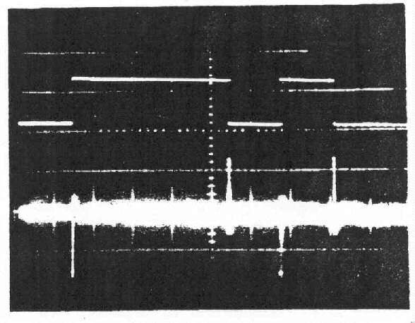
a. A-scope display
[b. Emanation display redacted.]
Figure 3-5. - Detected Impulsive Emanation Correlated to Both Transitions
of Digital Monitor Signal (Without Demodulator) (U) (C)
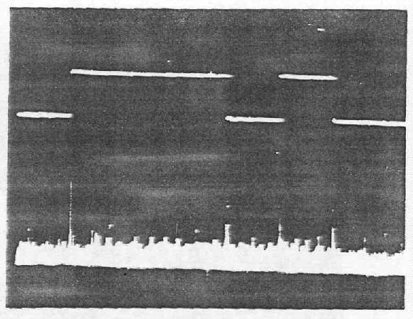
a. A-scope display
[b. Emanation display redacted.]
Figure 3-6.-Detected. Impulsive Emanation Correlated to Both Transitions
of Digital Monitor Signal (With Demodulator) (U) (C)
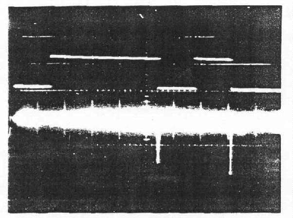
a. A-scope display
[b. Emanation display redacted.]
Figure 3-7.-Detected Impulsive Emanation Correlated to
Mark-to-Space Transitions of Digital Monitor Signal (U) (C)
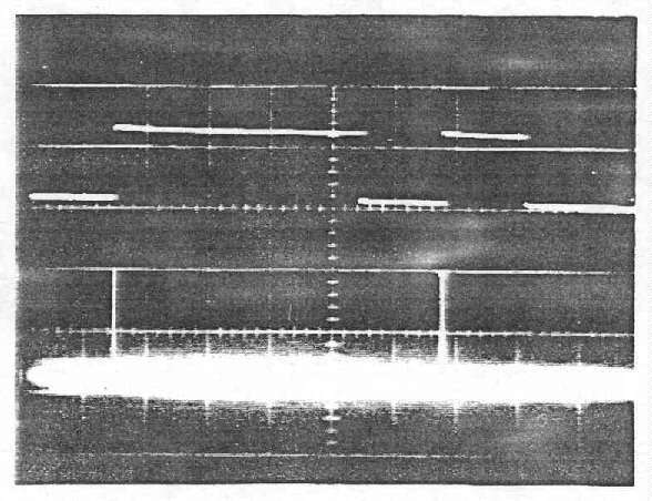
a. A-scope display
[b. Emanation display redacted.]
Figure 3-8.-Detected Impulsive Emanation Correlated to
Space-to-Mark Transitions of Digital Monitor Signal (U) (C)
(1) (C) [4 lines redacted.]
(2) (C) [5 lines redacted.]
(3) (C) [5 lines redacted.]
THIS PAGE IS INTENTIONALLY BLANK
4-1. (U) Introduction. -This chapter provides guidefines for the development of equipment which will be used to process national security information. This topic has been divided into two areas: ( 1) Design of equipment to meet TEMPEST requirements: and (2) facility design to maximize the TEMPEST integrity of the equipment/systems installed. More specific information is provided in the effective editions of NACSEM 5201* and NACSIM 5203*.
____________________
* For long title of this publication please see Table 6-1.
4-2 (C) Causes of TEMPEST Emanations (U). - In typical
baseband communication or data processing circuit designs, minimum attention
is given to suppression of unintentional emanations. Design engineers do
not realize the importance of component selection, interconnections, or layout
in minimizing signal emanations. Draftspersons, who are unfamiliar with
electrical engineering fundamentals, are frequently employed in the design
of PC boards and interconnecting leads. Occasionally, this chore is delegated
to a computer, which follows a minimal number of rules governing circuit
applications and circuit interconnections. As a result, undesired signal
emanations will probably be detected when the equipment must be proven TEMPEST
hazard-free.
a. (C) Continuous signals normally are called analog. They
occupy a restricted frequency range or spectrum called the baseband. If EUT
circuits are nonlinear and prone to parasitic oscillations at some frequencies
far removed from the signal frequency, emanations can occur as discrete carriers
modulated by the baseband analog signals. Even white noise existing at
frequencies removed from the analog signal frequencies can be modulated by
analog signals.
b. (C) Discrete refers to discontinuous signals such as
digital or pulse signals. They produce a spectrum of harmonics and subharmonics
of the bit rate. thus they occupy a frequency range far greater than that
of analog signals. Emanations can appear in either full-baud or impulsive
form.
c. (U) Electromagnetic fields accompany any circuit which has changing voltages and currents. These fields are in space surrounding the circuits, and their amplitudes are dependent on such factors as (a) voltage and current amplitude in the circuit; (b) voltage and current rates of change; (c) dimensions of the circuit; and (d) distance from the circuit. Therefore each circuit and its components can be thought of as antennas that generate electromagnetic fields which propagate through space -- each of which can cause CE.
d. (C) Conducted emanations may be introduced by:
(1) Crosstalk (capacitive and inductive coupling) between circuits, components, and wires within an EUT.(2) Common impedance coupling due to intentional or fortuitous common ground or power supply paths.
(3) Interception of space radiated emanations.
(4) Change in impedance which terminates the interface conductor in an EUT due to power demand changes during signal processing (e.g.. input impedance of diode-protected or clamped-line receiver input terminals).
(5) A driven wire, connected to an open switch or gate, is an example of an E-field radiator. A loop formed by a signal connection, power, and return path is an example of an H-field radiator.
4-3. (C) Equipment Design (U). - The prevention of
TEMPEST problems can best be accomplished by being attentive to the problem
throughout every stage of the equipment or system design and development.
Due to the many ways that information is processed in an equipment, there
are many ways that compromising emanations can be generated. It is nearly
impossible to completely prevent the generation of such compromising emanations.
Therefore, the TEMPEST design objectives should be to (a) keep the amplitude
and frequency spectrum of compromising emanations as low as possible (i.e.,
below the appheable limit); (b) prevent RED signals from coupling from RED
to BLACK lines or circuits; and (c) to prevent emanations from escaping from
the equipment through electromagnetic or acoustical radiation or through
line conduction. When involved in retrofitting non-TEMPEST designed equipments,
many of the methods identified herein, in addition to encapsulation techniques,
may be useful in meeting design objectives.
a. (U) Preventive Measures. - Identify RED signals and circuits. The identification of RED signals, RED signal paths and RED signal processing stages is an important factor in the early stages of the design of information-processing equipments. This identification serves as a basis for all preventive/containment methods which may follow.
b. (U) Functions and Format Selections. - It may be feasible during the early stages of development to choose among alternate internal RED data handling schemes or input/output techniques. The relative merits and short comings of the alternatives with respect to their probable TEMPEST performance should be weighed and should influence the choices.
c. (U) Signal Power Levels. - The signal operating levels of all RED data circuits and stages should be as low as possible in order to minimize propagating compromising emanations. A balance between the operational and TEMPEST factors should be achieved in the selection of operating levels and stage gains.
d. (C) Signal Spectrum Limits. (U) - The objective is to
limit the spectra of RED data signals in order to contain their energies
within the RED environment. Optimize the spectra limits and bandwidth of
RED digital and/or analog signals to maintain operational requirements such
as intelligibility and error rate which is required throughout the RED data
signal pathways.
(1) (C) The ideal way to limit the RED spectrum is to (a) use low-level signals, (b) use either low data rates or wide pulses, (c) use some type of filtering and/or slow rate control, (d) use nonreturn-to-zero (NRZ) format, (e) use the lowest allowed interface signal levels, and (f) use balanced outputs. Also, pulse shaping will contribute immensely to RED spectrum control.(2) (
C) Often the spectrum of the RED input line signals may require control. There are four general solutions to the problem of RED input spectrum control:(a) (C) Insure that the flow through the RED input ground return consists only of ground return currents from only the external signal source. Balanced inputs are preferred.(b) (
C) Use a filter to reduce signals coupled from the input compartment to the RED input terminal.(c) (
C) Exercise care in routing input leads so that they pick up a minimum of internal RED signals.(d) (
C) 'Choose input devices and amplifiers carefully so that neither nonlinear loading of the input line nor parasitic oscillations will be introduced.
e. (U) Circuit Arrangement and Layout. - The primary TEMPEST-related goal in circuit layout is the prevention of coupling from RED signal processing circuits onto BLACK circuits. This requires such practices as separation of RED signal processing circuits from BLACK circuits and minimizing interelement and intercircuit RED signal paths.
Note: See NACSEM 5201 * for specific design techniques which should be utilized to meet TEMPEST requirements.
____________________
* For long title of this publication please see Table 6-1.
f. (U) Return Path Layout. - Appreciable impedances can and do exist between various points of the return paths for power and signal currents. These impedances can result in unintentional intercircuit signal coupling, spurious signal generation, and other signal ills which can have both direct and indirect TEMPEST implications. The primary goals are to avoid excessive return path lengths and impedances in the common returns and especially where possible, avoid any common return paths which will carry both RED and BLACK return currents.
g. (U) Stage Decoupling. - Decoupling at the stage or module level may be necessary for the prevention of TEMPEST problems. Without adequate decoupling, currents and voltages representing compromising emanations can be propagated from an originating element to and through the equipment power supply via power leads.
h. (U) Shielding. - Shielding may be applied at many levels from the individual stage to the entire data processing or communication terminal installation. Shielding separates two regions so that in passing from one to the other an electric or magnetic field (or both) is attenuated by reflection and absorption losses. Shielding can be accomplished with conductor and/or cable shields, conduit, gaskets, magnetic foils, screens, and shielded enclosures.
i. (U) Filtering. - A filter functions to transmit signals of certain frequencies while attenuating all others. The filters used for compromising emanation containment usually are interference reduction types. They are used on signal Lines, control lines, and powerlines. To perform effectively, they must be selected with care (in some cases special designs are required) and located and installed in accordance with estabhshed guidelines.
j. (U) Isolation. - Isolators are devices which perform certain amounts of isolation through attenuation or insertion loss between a source and a load. Their function is similar to filters, but their characteristics are usually superior. Circuit isolation is achieved through the use of transformers, feedback amplifiers, or optical couplers. Other devices useful in powerline isolation are active powerline filters.
4-4. (U) Facility Design. - The national policy objective is to assure that national security information is not lost through unintentional emanations. To achieve this, equipments should be designed to meet TEMPEST requirements and be tested to verify comphance with TEMPEST specifications. However, poor installation practices can create system or facility problems even though all system components are TEMPEST acceptable. Additionally, a large number of installations may be made utilizing non-TEMPEST approved equipments and in these instances, proper facility design is imperative.
a. (U) The RED/BLACK concept is the basis for the development of the facility criteria presented herein. The RED/BLACK concept dictates that electrical and electronic circuits, components, equipments, systems, etc., which handle national security plain language information in electrical signal form (RED) be separated from those which handle encrypted or unclassified information (BLACK). Under this concept, RED and BLACK terminology is used to clarify specific criteria relating to the difference between such circuits, components, equipments. systems, etc., and the areas in which they are contained.
b. (U) RED/BLACK guidelines have been developed which detail the procedures required to provide proper equipment and system shielding, separation, grounding and filtering so that TEMPEST signals are minimized. The detailed requirements for these areas, as they apply to specific types of installations, are contained in the effective edition of NACSIM 5203.*
____________________
* For long title of this publication please see Table 6- 1.
THIS PAGE IS INTENTIONALLY BLANK
5-1. (C) Determinatiou of Requirements (U). -
The TEMPEST requirements which are to be imposed on equipment/systems being
designed are contained in the effective edition of NACSIM 5100.* These
requirements should be specified as design limits for all new national security
information-processing equipments, and include:
(U) Electric Field Radiation. - Tests performed with the antenna one meter from the EUT.(U) Magnetic Field Radiation. - Tests performed with the antenna one meter from the EUT.
(U) BLACK Line Conduction. - Tests performed on a.c. powerlines, d.c. powerlines, signal lines, and control lines utilizing a direct voltage tap.
(
C) [2 lines redacted.](
C) [2 lines redacted.]( U) RED Line Conduction. - Tests performed on RED Unes to determine the signal spectrum.
a. (U) The actual signal emanations limits which must be met for the above test areas are based on the test category(ies) into which the RED signals of the EUT fall (see Table 3-3). These are also provided in the effective edition of NACSIM 5100.* The specification Emits were developed considering ambient noise (radiation Emits); receiver noise (BLACK line conducted limits); and the signal-to-noise ratio required to recover information for various types of emanations.
b. (U) As presented earlier (see Paragraph 3-1d.), each RED signal within a processor must be identified and considered as a potential source, thus specific TEMPEST requirements must be developed for each of the signals so identified. It may be possible, due to similiarity of data rates, type of data format, wave shaping, etc., to consohdate or eliminate certain tests. Thus the final determination as to actual requirements to be imposed should be made by a quafified TEMPEST engineer.
5-2. (U) TEMPEST Data. - Table 5-1 should be considered for inclusion in any contract where TEMPEST requirements are imposed. Again the agency's TEMPEST engineer should make the final determination as to which data items are required to enable an adequate evaluation of the equipment meeting TEMPEST requirements.
5-3. (U) TEMPEST Support. - As mentioned in Paragraph 5-1b, the support of a qualifted TEMPEST engineer is necessary to ensure that sufficient and appropriate TEMPEST requirements are included in all contracts for the development and/or production of equipments which will be utilized to process national security information. This support should be requested from the TEMPEST organization within your department or agency. Table 5-2 lists a few government agencies that will provide competent guidance. Agencies/departments who want to be tested should call the National Security Agency,
TABLE 5-1 TEMPEST DATA (U) (U) |
|
| Document | Document Data Item Description No. |
| (1) TEMPEST Control Plan
(2) TEMPEST Test Plan (3) TEMPEST Test Facility Evaluation Report (4) TEMPEST Test Detection System Evaluation Report (5) TEMPEST Test Setup Ambient Control Report (6 ) TEMPEST Test Evaluation Report |
T-5245
T-5140B T-5181A T-5182A T-5183A T-5180A |
TABLE 5-2 REFERENCES TO TEMPEST DATA (U) (U) |
|
| Department/Agency | Reference |
| National Security Agency | Director, National Security Agency ATTN: S643 Ft. George G. Meade, MD 20755 301-688-6862 AUTOVON 235-6862 |
| Navy | C.O. Naval Electronic Systems Security Engineering Center (Code-220) 3801 Nebraska Avenue, NW Washington, DC 20390 202-282-0411 AUTOVON 292-0411 |
| Air Force | U.S. Air Force Cryptologic Support Center (EPV) San Antonio, TX 78243 512-925-2511 AUTOVON 945-2511 |
| Army | Commander, U.S. Army Intelligence & Security Command ATTN: IAOPS-OP-P Arlington Hall Station, Arlington, VA 22212 703-692-5102 AUTOVON 222-5102 |
6-1. (U) General. - This chapter provides a listing of current TEMPEST documentation available within the U.S. Government. If copies of listed publications are required, the request should be made to the department or agency SCOCE representative.
6-2. (U) Organizational Level Documents. - The majority of departments and agencies within the SCOCE community have issued implementing publications on the TEMPEST program. For information on these publications and their availability you should contact the references provided in Table 5-2.
TABLE 6-1 NATIONAL LEVEL PUBLICATIONS |
||
Short Title |
Class |
Long Title |
| MIL-HDBK- 419 | U |
Grounding, Bonding, and Shielding for Electronic Equipments and Facilities (U) (To be Published) |
| MIL-STD-1680A/SH | C |
Installation Criteria for Shipboard Secure Processing Systems (U) |
| NACSI 4003* | S |
Classification Guidelines for COMSEC Information (U) |
| NACSI 5001 | C |
Standardization of Compromising Emanations Laboratory Test Procedures (U) |
| NACSI 5002 | C |
Suppression of Compromising Emanations through Low-Level Operation (U) |
| NACSI 5003 | C |
Basis for Electromagnetic Compromising Emanations Limits (U) |
| NACSIM 5000 | C |
TEMPEST Fundamentals (U) |
| NACSIM 5001 | C |
TEMPEST Procurement Guidelines (U) (To be published) |
| NACSIM 5002 | C |
Technical Rationale: Basis for Electromagnetic Compromising Emanations Limits (U) |
| NACSIM 5100A | C |
Compromising Emanations Laboratory Test Requirements, Electromagnetics (U) |
| NACSIM 5101A | S |
Technical Rationale for Compromising Emanations Laboratory Test Requirements, Electromagnetics and Controlled Space Evaluation Procedures (U) (To be published) |
| NACSEM 5103 | C |
Compromising Emanations Laboratory Test Standard, Acoustics (U) |
| NACSEM 5104 | S |
Technical Rationale for Compromising Emanations Laboratory Test Standard, Acoustics (U) |
| NACSEM 5105 | C |
Administrative GuideLines for Compromising Emanations Laboratory Test Standard Acoustics (U) |
| NACSEM 5106 | S |
Compromising Emanations Analysis Handbook (U) |
| NACSEM 5108 | U |
Receiver and Amplifier Characteristics Measurement Procedures (U) |
| NACSEM 5109 | C |
TEMPEST Testing Fundamentals (U) |
| NACSEM 5110 | S |
Facility Evaluation Criteria - TEMPEST (U) |
| NACSIM 5111 | C |
Controlled Space Evaluation Procedures (U) (To be published) |
| NACSEM 5112 | S |
NONSTOP Evaluation Techniques (U) |
| NACSEM 5201 | C |
TEMPEST Guidelines for Equipment/System Design (U) |
| NACSIM 5203 | C |
Guidelines for Facility Design and RED/BLACK Installation (U) |
| NACSEM 5204 | C |
Shielded Enclosures (U) |
| NCSC 3* | S |
TEMPEST Glossary (U) |
| NCSC 4* | C |
National Policy on the Control of Compromising Emanations (U) |
| * Not releasable to contractors or contractor representatives. | ||
THIS PAGE IS INTENTIONALLY BLANK
A.1. (U) Introduction. - The terms Usted and defined herein, are those which are directIv related to the TEMPEST discipline. Engineering and technical terms in common use are not included in this Glossary unless their definitions are altered when these terms are applied to the TEMPEST discipline.
A
Access (U) - The ability and opportunity to obtain knowledge of national security information or to be in a place where one could be expected to gain such knowledge.
Acoustic Emanation (U) - Emanations in the form of free-space acoustical
energy produced by the operation of a purely mechanical or electromechanical
device equipment. Such emanations may be compromising under the definition
of "compromising emanations". (C)
Ambient Level (U) - Ambient levels may be classified into two categories: (a) Test Environment Ambient Level -- Those levels of radiated and conducted noise existing at a specified test location and time when only the equipment under test is inoperative. Atmospherics, interference from other sources, and circuit noise or other interference generated within the test detection system comprise the "test environment ambient level''. (b) Equipment-Under-Test Ambient Level -- Those levels of radiated and conducted noise which originate in the equipment under test and are not compromising emanations.
Ambiguity (U) - A condition which precludes positive identification of specific characters and functions utilizing the parameters of the detected signal. This condition exists when the intelligence-related signal emanation can be equated to more than one character or function.
Average Depth of Correct Characters (ADCC) (U) - [3 lines redacted.]
(C)
B
Bit Density In formation (U) - [4 lines redacted.] (C)
BLACK (U) - A term applied to wire lines, components, equipment, and systems which do not handle national security signals, and to areas in which no national security signals occur.
BLACK Line (U) - Any Une, other than primary or secondary RED conductors, external to national security information-processing equipment.
BLACK Signal (U) - Any signal (e.g.. control signal or enciphered signal) which would not divulge national security information if recovered and analyzed.
C
Communications Security (COMSEC) (U) - The protective measures taken to deny unauthorized persons information derived from telecommunications of the United States Government related to national security and to ensure the authenticity of any such communications. Such protection results from the application of security measures (including cryptosecurity, transmission security, and emissions security) to electrical systems generating, handling, processing, or using national security information. It also includes the application of physical security measures to communications security information or materials.
Compromise (U) - Any occurrence which results in unauthorized persons gaining access to national security information.
Compromising Emanations (CE) (U) - Unintentional intelligence-bearing signals which, if intercepted and analyzed, disclose the national security information transmitted, received, handled or otherwise processed by any information-processing equipment.
Compromising Emanation Performance Requirement (CEPR) (U) - The maximum emanation level permitted at the standard measurement point. When the CEPR is met, there will be minimal chance that a compromising emanation will be detected beyond the specified design radius.
Control Line (U) - Line intended for the transmission of control signals, alarm indicators and fault determination between components of a system.
Controlled Space (U) - The three-dimensional space surrounding equipments that process national security information within which unauthorized personnel (1) are denied unrestricted access and (2) are either escorted by authorized personnel or are under continual physical or electronic surveillance.
Correlated Emanations (CORR E) (U) - Detected emanations which correspond to or contain a discernible relationship to any signal or process of known characteristics. Correlated emanations may be compromising under the definition of "compromising emanations".
Countermeasure (U) - An action, procedure, modification, or physical device which is applied to reduce or to inhibit the generation of compromising emanations.
D
Data Related Emanations (DRE) (U) - Detected emanations which have a discernible relationship with a signal related to the data processed by the EUT, and have been analyzed and determined to be not compromising.
Design Radius (U) - The radius of the sphere within which compromising emanations, from an equipment located at its center will be contained when the equipment meets the compromising emanation performance requirements.
Digraphic Information (U) - [3 lines redacted.]
Digraphic Processing (U) - Processing where the data (bits) are parallel processed, and the characters are processed two at a time.
Dry Line (U) - An interface line of the equipment under test which does not carry any signals while TEMPEST tests are in progress.
E
Emanation (U) - Unintended signals or noise appearing external to an equipment.
Emanations Security (EMSEC) (U) - This term is no longer used. The definition of telecommunications has been expanded and emission security encompasses the old definition of emanations security.
Emission Security (U) - That component of communications security (COMSEC) which results from all measures taken to deny unauthorized persons information of value which might be derived from intercept and analysis of compromising emanations from crypto-equipment and telecommunications systems.
Equipment Radiation TEMPEST Zone. (ERTZ) (U) - A zone established as a result of determined or known equipment radiation TEMPEST characteristics. The zone includes all space within which a successful hostile intercept of compromising emanations is considered possible.
Equipment Under Test (EUT) (U) - An equipment or group of equipments subjected to TEMPEST testing,
EUT Exerciser Equipment (U) - Any equipment or device (not part of the EUT) used during TEMPEST testing to make the equipment under test (EUT) operate, e.g., a similar or complementary equipment for back-to-back operation or an external clock source. This term may be used interchangeably with EUT stimulus equipment.
F
Facility (U) - A physically definable area consisting of a controlled. space which contains national security information-processing equipments.
Fingerprint Signal (U) - A unique emanation caused by the processing or transfer of an information unit character, byte, etc.) by the EUT. (Also called signature.)
Fortuitous Conduction (U) - Emanations in the form of signals propagated along any unintended conductor. Such emanations may be compromising under the definition of "compromising emanations".
Fortuitous Conductor (U) - Any conductor which may provide an unintended path for signals. Fortuitous conductors include cables, wires, pipes, conduits, and structural metal work in the vicinity of a radiation source.
Full Bit Emanation (U) - An emanation which correlates on a one-to-one basis with the bits of the message code signal.
G
Generatrix (U) - The set of letters which are considered to be the cause of a particular received TEMPEST signal, arranged in order of probability.
Generatrix Family (U) - The groups (sets of generatrices) into which the letters of the alphabet are assigned by the TEMPEST encoder. Also, the groups into which the letters are assigned at the output of the detector for analysis purposes.
Generatrix Sequence (U) - The sequence of generatrices resulting from a test, where a representative test message for the EUT is processed: one generatrix for each received signal.
H
Hazard (U) - A measure of both the existence and the compromising nature of an emanation. A hazard exists if and only if compromising emanations are detectable beyond the controlled space.
I
Impulsive Emanation (U) - An emanation composed of impulses,
Information Ratio (IR) (U) - A measure of the amount of information which can be derived from a detected signal. It is the ratio of the amount of information contained in a signal to the amount of information necessary for 100 percent recovery of plaintext information.
L
Line Conduction (U) - Emanations produced on any external or interface line of an equipment which, in any way alter the signal on the external or interface lines. The external lines include signal lines, control and indicator lines, and a.c. or d.c. powerlines.
M
Monitor Signal (U) - The signal to which a detected emanation is compared for determining correlation: a monitor is usually a RED signal.
Monographic Information (U) - [3 lines redacted.]
Monographic Processing (U) - Processing where each character is sequentially processed in a bit parallel format.
Multichannel Information (U) - Information which results when emanations from multiple TEMPEST channels are used to extract information correlating to a single message being processed.
N
Noise (U) - Disturbances superimposed upon a signal that tend to obscure its information content.
Nontunahle (U) - A term used to describe a test, or test instrumentation, in which frequency coverage is selected in one or more discrete increments; i.e., not continuously variable. Nontunable detection systems do not contain a demodulator.
P
Parallel Information Unit (U) - Two or more bits arranged in a deterministic order which are transferred or stored simultaneously as a unit. One parallel information unit is transferred when a clock or trigger pulse causes the entire unit to be simultaneously gated out of a register or other storage device. Two or more units can form a larger unit.
Polygraphic Information (U) - [2 lines redacted.]
Polygraphic Processing (U) - Processing where the data (bits) are parallel processed, and the characters are processed more than one at a time.
Powerline Conduction (U)--See Line Conduction.
[2 lines redacted.]
[3 lines redacted.]
Primary Red Conductor (U) - Any conductor intended to carry national security information and terminating in RED equipment or in the RED side of crypto-equipment or isolation devices.
R
Recoverable Zone (U) - The three-dimensional space surrounding an equipment or system processing national security information within which it is theoretically possible to recover the information processed. For radiated signals, this term may be used interchangeably with Equipment Radiation TEMPEST Zone (ERTZ).
RED (U) - A term applied to wirelines, components, equipment, and systems which handle national security signals, and to areas in which national security signals occur.
RED/BLACK Concept (U) - The concept that electrical and electronic circuits, components, equipments, systems, etc., which handle national security plain language information in electric signal form (RED) be separated from those which handle encrypted or non-national security information (BLACK). Under this concept, RED or BLACK terminology is used to clarify specific criteria relating to, and to differentiate between such circuits, components, equipments, systems, etc., and the areas in which they are contained.
RED Line (U) - A primary or secondary RED conductor.
RED Signal (U) - Any signal (e.g., plain text, key, subkey, initial fill or control signal) which would divulge national security iriformation if recovered.
Risk (U) - The probability that a hostile entity will successfully exploit a particular telecommunications or COMSEC system for intelligence purposes; its factors are threat and vulnerability.
S
SCOCE (Subcommittee On Compromising Emanations) (U) - This subcommittee, composed of representatives from various government organizations, is charged with specific responsibilities designed to implement Government-wide programs for the control and suppression of compromising emanations. In carrying out these responsibilities it is an instrument for exchanging technical TEMPEST information, techniques, and criteria among Government organizations and their contractors.
Secondary RED Conductor (U) - Any conductor, other than primary RED, which connects to RED equipment, the RED side of crypto-equipment, or the RED side of isolation devices, which does not intentionally carry national security information; but because the coupling mechanism with the RED equipment might carry compromising infoIrmation, is designated secondary RED (e.g., indicator lines, control Lines, timing lines, etc.). Power distribution panels and grounding systems serving RED wire lines and equipments may also be so designated.
Short Cycle Operation (U) - A method employed in TEMPEST testing of cryptographic
equipments to facilitate identification of key-correlated emanations; whereby,
the equipment is modified to generate a repetitive key. (C)
Signal (U) - A fluctuating quantity, such as voltage, current. electrical field strength, sound pressure level, etc., the variations of which convey irfformation.
Skewed Parallel Signal (U) - [3 lines redacted.] (C)
Standard Measurement Point (U) - The point where the compromising emanation performance requirement (CEPR) applies. For an electric or magnetic field emanation, the standard measurement point is one meter from the equipment under test. For a conducted emanation, the standard measurement point is at the design radius.
T
Telecommunications (U) - The transmission, communication, or processing of information, including the preparation of such information, by electrical, electromagnetic, electromechanical or electro-optical means. (Note: This definition includes the processing of information by noncommunicating equipment.)
TEMPEST (U) - A short name referring to investigations and studies of compromising emanations. It is often used synonymously for the term "compromising emanations", e.g., TEMPEST tests, TEMPEST inspections.
TEMPEST Channel (U) - An unintentional communications channel which conveys information about the information processed through the intentional communications channel.
TEMPEST Encoding (U) - An unintentional process which results in the altering of information before it is emitted into the TEMPEST channel.
TEMPEST Test (U) - A laboratory or on-site (field) test to determine the nature and ampliude of conducted or radiated signals containing compromising information.
Test Detection System (U) - The instrumentation used in performing a TEMPEST test including the transducer, detector, display devices, recording devices, filters, coaxial switches, etc.
Test Message (U) - A series of characters or signals chosen to be processed by the equipment under test during TEMPEST testing.
Transition Density Information (U) - [4 lines redacted.] (C)
Tunable (U) - A term used to describe a test, or test instrumentation designed to cover a fixed frequency range in continuous or stepped contiguous (within the specified bandwidth) increments. Tunable detection systems may contain a demodulator.
U
Undesired Signal Data Emanations (USDE) (U) - Compromising emanations or a primary RED line amplitude density spectrum which exceeds Emits specified in the applicable TEMPEST standard.
W
Wet Line (U) - An interface line of the equipment under test, where the signal normally transmitted over the line is present.
B.1. (U) General. - The director, National Security Agency, has responsibilily for providing guidance on security classification and control of information pertaining to compromising emanations including the releasability of this information to foreign nationals.
B-2. (U) Scope. - These new guidebries cover information relating to the control of compromising emanations. These guidelines take precedence over those in ANNEX C of NACSI 4003, dated 1 December 1978. If a superseding edition of NACSI 4003 should contain different guidelines, this appendix will be changed accordingly.
B-3. (U) Rationale. - Compromising emanations information shall be classified based on provisions of Executive Order 12065, "National Security Information," dated 20 June 1978.
a. (C) Specific information will be classified as discussed
in Paragraph B.6. below if it:
(1) (C) Focuses attention on a valuable U.S. Intelhgence source or a critical U.S. security deficiency of which many foreign governments are not yet aware.(2) (
C) Indicatess the vulnerability to exploitation via compromising emanations of a specific U.S. facility at which national security information is processed.(3) (
C) Indicates the vulnerability to exploitation via compromising emanations of a specific type or model of equipment or system used to process national security information.(4) (
C) Indicates specific countermeasures or corrective actions taken on a specific equipment. system or at a facility when identified as being for the purpose of controlling compromising emanations.(5) (
C) Indicates unique techniques for the detection, analysis or control of compromising emanations.
b. (U) The following guidelines describe various aspects of the compromising emanations problem and provide levels of classification which shall be assigned to this information. The levels of classification indicate the minimum levels of protection which shall be afforded a particular category of compromising emanaiions information. (It may be necessary to assign higher levels of classification to specific categories of compromising emanations information depending on such factors as: (a) the widespread usage of a particular equipment or system used to process classified information: (b) the location of an equipment/system in a Hazardous Aciivity Country as defined by DCID 1/20; (c) the level or sensitivity of the traffic being processed by a particular equipment, system or site; and (d) the severity of the TEMPEST problem associated with a particular equipment, system, or site.*
____________________
* Does not apply to contractors.
c. (U) Unclassified information concerning compromising emanations shall not be discussed or made available to persons without a need-to-know, especially when the aggregate of unclassified information could be combined to reveal classified information. No person is entitled to knowledge, possession of, or access to, information concerning compromising emanations solely because of his office, position or type of clearance. No information related to the subject of compromising emanations shall be released for public consumption through the press, advertising, radio, TV or other public media without specific written approval from the Director, National Security Agency.
d. (U) The use of commercial telephones for the discussion of TEMPEST information is discouraged. Unclassified information can easily be combined to reveal classified information. Attempts to "talk around" classified TEMPEST information should be avoided.
B.4. (U) Marking. - Compromising emanations information classified in accordance with these guidelines should be indicated either on the individual page where the information appears or on the front cover of the document in which it is contained, as follows:
Classified by NACSI 4003
Review on _____________________ (Insert date 20 years from date of origin)
B.5. (U) Foreign Release. - Classified TEMPEST information may be released to foreign nationals only when authorized by the Director, National Security Agency. Address requests for authorization to Director, National Security Agency, ATTN: S04, Fort George G. Meade, MD 20755. Each publication which contains classified TEMPEST information shall have the following notation placed on its Letter of Promulgation, Handling Instructions or title page.
"This publication or the information it contains may not be released to foreign nationals without prior specific approval from the Director, National Security Agency. All approvals will identify the specific information or copies of this publication authorized for release to specific foreign holders. All requests for additional issuances must receive prior specific approval from the Director, National Security Agency."
B.6. (U) Specific Guidelines. - This appendix contains classification guidelines which relate only to TEMPEST information. Terms, details of testing, test data, etc., related to standard Radio Frequency Interference (RFI), Electromagnetic Interference (EMI) or Electromagnetic Compatibility (EMC) testing are unclassified and are not dealt with within these guidelines. These guidelines cover the most common occurrences: if circumstances arise which are not covered by these guidelines, the originator must determine a classification on the rationale contained in Paragraph B.3 above.
B.7. (U) TEMPEST Classification Chart Outline. - The following is a TEMPEST classification chart to assist in specific problems. The contents of this chart are:
a. (U) Terms (when associated with TEMPEST) and Definitions.
b. (U) Policy.
c. (U) General TEMPEST Statements.
d. (U) Procedures. Techniques, and Specifications.
e. (U) Facility and Laboratory Tests.
B.8. (C) TEMPEST Classification Chart (U).
| a. ( |
||
Terminology |
Classification |
|
Term |
Definition |
|
| 1. (U) Acoustic Emanation | UNCLASSIFIED | CONFIDENTIAL |
| 2. (U) Average Depth of Correct Character (ADCC) | UNCLASSIFIED | CONFIDENTIAL |
| 3. (U) Bit Density Information | UNCLASSIFIED | CONFIDENTIAL |
| 4. (U) Compromising Emanations (CE) | UNCLASSIFIED | UNCLASSIFIED |
| 5. (U) Controlled Space (CS) | UNCLASSIFIED | UNCLASSIFIED |
| 6. (U) Digraphic Information | UNCLASSIFIED | CONFIDENTIAL |
| 7. (U) Emission Security | UNCLASSIFIED | UNCLASSIFIED |
| 8. (U) Fortuitous Conduction (FC) | UNCLASSIFIED | UNCLASSIFIED |
| 9. (U) Information Ratio (IR) | UNCLASSIFIED | UNCLASSIFIED |
| 10. (U) Line Conduction (LC) | UNCLASSIFIED | UNCLASSIFIED |
| 11. (U) Monographic Information | UNCLASSIFIED | CONFIDENTIAL |
| 12. (U) Polygraphic Information | UNCLASSIFIED | CONFIDENTIAL |
| 13. ( |
CONFIDENTIAL | CONFIDENTIAL |
| 14. (U) Powerline Conduction | UNCLASSIFIED | UNCLASSIFIED |
| 15. ( |
CONFIDENTIAL | CONFIDENTIAL |
| 16. ( |
CONFIDENTIAL | CONFIDENTIAL |
| 17. (U) Short Cycle Operation | UNCLASSIFIED | CONFIDENTIAL |
| 18. (U) Skewed Parallel Signal | UNCLASSIFIED | CONFIDENTIAL |
| 19. (U) Telecommunications | UNCLASSIFIED | UNCLASSIFIED |
| 20. (U) TEMPEST | UNCLASSIFIED | UNCLASSIFIED |
| 21. (U) Transition Density Information | UNCLASSIFIED | CONFIDENTIAL |
| 22. (U) Undesired Signal Data Emanations (USDE) | UNCLASSIFIED | UNCLASSIFIED |
Classification |
|
| b. (U) Policy. - Information indicating the U.S. Government's National Level policies, programs, responsibilities or resources for the control of compromising emanations. | CONFIDENTIAL |
| c. General TEMPEST Statements (U). | UNCLASSIFIED |
(1) (U) The statement, without giving details, that a specific plaintext processing equipment/system has TEMPEST deficiencies. (If any specifics are provided, see Paragraph 8e). |
UNCLASSIFIED |
(2) (U) The statement that a TEMPEST-suppressed version of a plaintext processing equipment/system is available. (If any specifics are provided, see Paragraph 8e). |
UNCLASSIFIED |
(3) ( |
|
(a) (U) Electromagnetic Radiation, Line Conduction |
UNCLASSIFIED |
(b) (C) xxxxxxxxxxxxxx, Acoustic Radiation |
CONFIDENTIAL |
(4) (U) The statement that a specific equipment/system has been scheduled for a TEMPEST test. |
UNCLASSIFIED |
(5) (U) The statement that a specific facility has been scheduled for TEMPEST test. |
UNCLASSIFIED |
| d. ( |
|
(1) ( |
CONFIDENTIAL |
(2) ( |
SECRET |
(3) ( |
TOP SECRET |
| e. ( |
||
Statement |
Classification |
|
Facility |
Laboratory | |
(1) ( |
||
(a) (U) Emanations within a CS or below a specification limit (i.e., CE) which compromise plaintext. |
SECRET | CONFIDENTIAL |
(b) ( |
SECRET | SECRET |
(2) (U) The statement, without revealing specific details, that an equipment/system has been modified to meet TEMPEST requirements or that TEMPEST vulnerabilities have been corrected. |
CONFIDENTIAL | UNCLASSIFIED |
(3) (U) Information that specific TEMPEST vulnerabilities have been corrected at a facility or with a specific equipment/system. |
SECRET | CONFIDENTIAL |
(4) ( |
SECRET | CONFIDENTIAL |
(5) (U) Requests for exception to the national policy or endorsements thereto for a facility which has USDE in which: |
||
(a) (U) No specific details are provided. |
CONFIDENTIAL | N/A |
(b) (U) Specific details concerning the detected emanations and/or control measures are given. |
SECRET | N/A |
(6) (U) Indications of RED/BLACK installation deficiencies, as a result of visual inspection, which in the judgement of the inspectors are: |
||
(a) (U) Likely to compromise the TEMPEST security of the inspected facility. |
SECRET | N/A |
(b) (U) Unlikely to compromise the TEMPEST security of the inspected facility. |
CONFIDENTIAL | N/A |
(7) (U) Information concerning the Controlled Space (CS) of a facility or equipment/system which provides details of the area over which positive control is exercised. |
CONFIDENTIAL | N/A |
LIST OF EFFECTIVE PAGES (U) Blank pages are not indicated in the "Page No. Column" if within a group of page numbers. All blank pages, except foldouts, are accounted for by the page number in the lower corner of the page and the notation "This Page is Intentionally Blank" centered on the page. Foldouts will be accounted for on the page preceding the blank page. For example, if page 128 is blank, page 127 will reflect the number "127/(128 blank)" in the lower corner on the printed page. A zero in the "Amend No." column indicates an original page.
Page No. Amend No. Front Cover ---------------------------- 0 i-x ------------------------------------ 0 1-1 -- 1-8 ----------------------------- 0 2-1 -- 2-4 ----------------------------- 0 3-1 -- 3-14 ---------------------------- 0 4-1 -- 4-4 ----------------------------- 0 5-1 -- 5-2 ----------------------------- 0 6-1 -- 6-2 ----------------------------- 0 A-1 -- A-6 ----------------------------- 0 B-1 -- B-6 ----------------------------- 0 Back Cover (Reverse Blank) ------------- 0 |
THIS PAGE IS INTENTIONALLY BLANK
COMMENT FORM
for
(Classify accordingly.)
Use one form per comment. Return completed form to:
Director
National Security Agency
ATTN: Chairman, SCOCE. S64
Fort George G. Meade. Maryland 20755
1. Date:
2. Name of Contributor:
3. Name of Organization:
4. Address of Organization:
5. Reference Section in document (paragraph, page number. line number if required: if general comment describe subject to be discussed:
6. Comment (What should be changed?):
7. Alternative (What should it be changed to?):
8. Rationale (why should change be made?):
If more space is required for any of the above items, use extra sheet(s) and attach to this form.
(Classify accordingly.)
3 BLANK PAGES
Transcription and HTML by Cryptome.