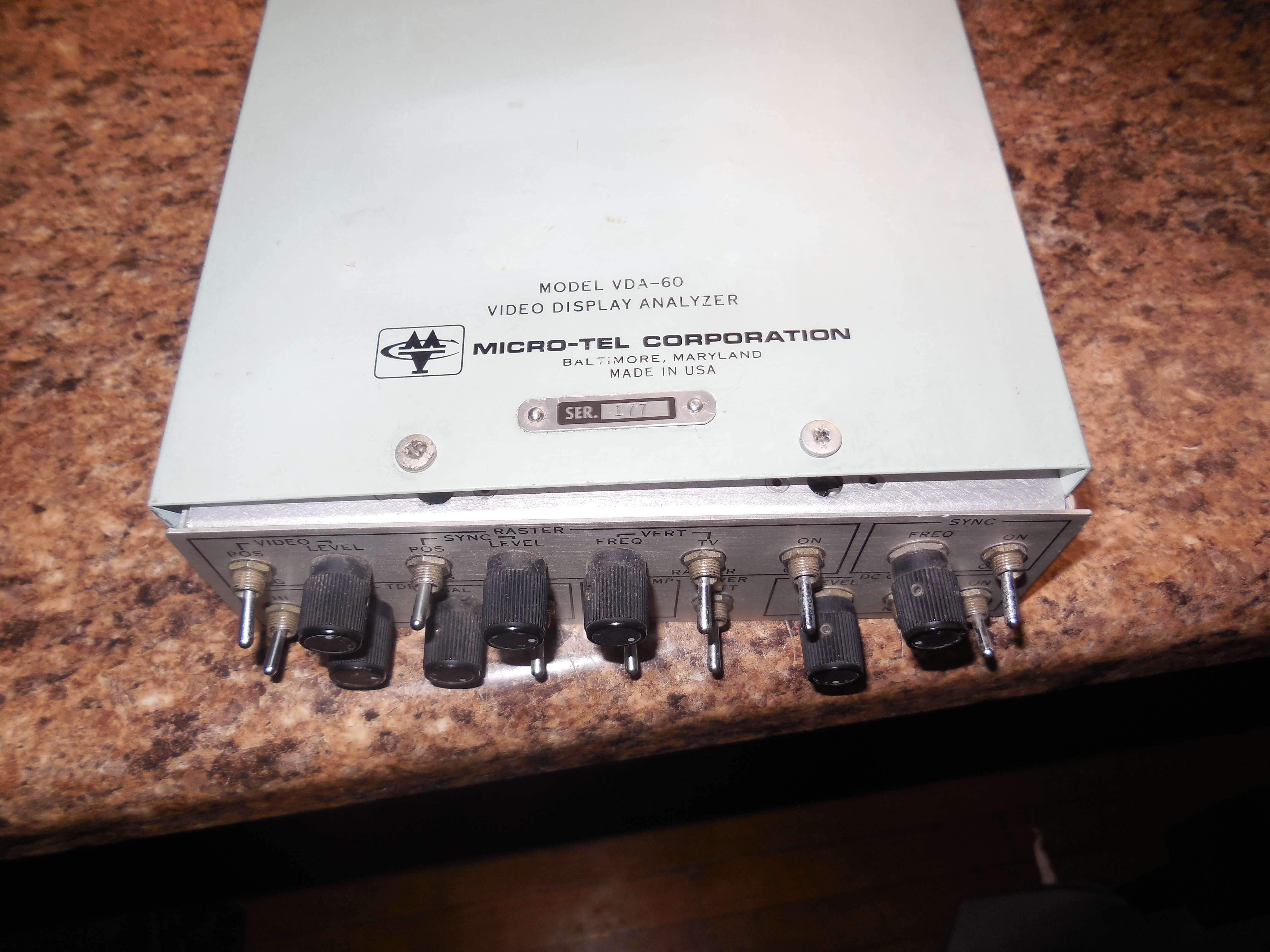
This is a series of pictures and notes for a Micro-Tel Corp. VDA-60 Video Display Analyzer (Ser. 177) found at a hamfest for $5!
I'll probably end up donating it the Crypto Museum, but I wanted to document as much as possible. The unit appeared to have some work done to it, with U2 replaced with a SK9144. The date codes on the ICs are all from the early 1980s.
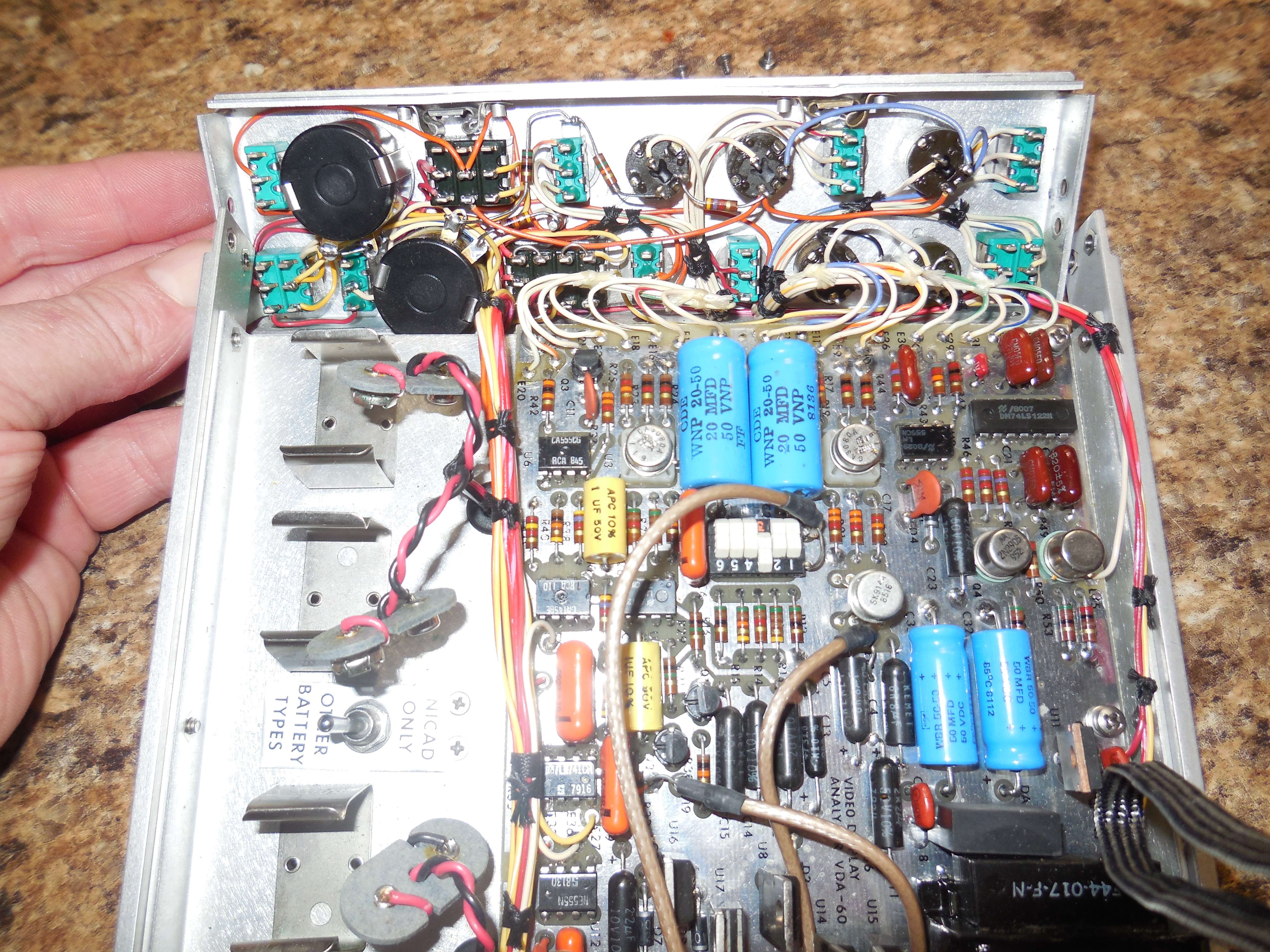
It look surprisingly simple. At least a quarter of the board is taking up with a conventional linear power supply (+/- 18V, +/- 12V, +/- 6V, +5V).
There is a DIP switch, but it function is unlabeled. It switches in resistors on the RASTER - IN input. The one here has "3" selected, which adds a series 5.1 kΩ resistor on the input.
The Micro-Tel VDA-60 Video Display Analyzer is a multi-function unit which enhances the utility of the MSR-902 and oscilloscope. It provides the following functions:
- RASTER: Generates a "falling raster" or television signal.
- SYNC: Variable frequency source to externally synchronize an oscilloscope.
- TDR: Two pulse signal formats for time domain reflectometry measurements.
- VIDEO: Wide-band, high-gain video amplifier.
- DC OFFSET: Variable DC offset for oscilloscope input.
Notes & Links
- Micro-Tel VDA-60 Raster Analysis "van Eck" System For sale ad.
- Kaiser RAS-515A Raster Analysis System
- TEMPEST 101 by James M. Atkinson
- Video Signal Eavesdropping Threat Tutorial by James M. Atkinson
- Beyond van Eck Phreaking by John J. Williams
- Operating & Maintenance Manual for Micro-Tel PR-700B
- Instruction Manual for MSR-904A Microwave Receiver
Micro-Tel Corporation VDA-60 Video Display Analyzer - Parts List
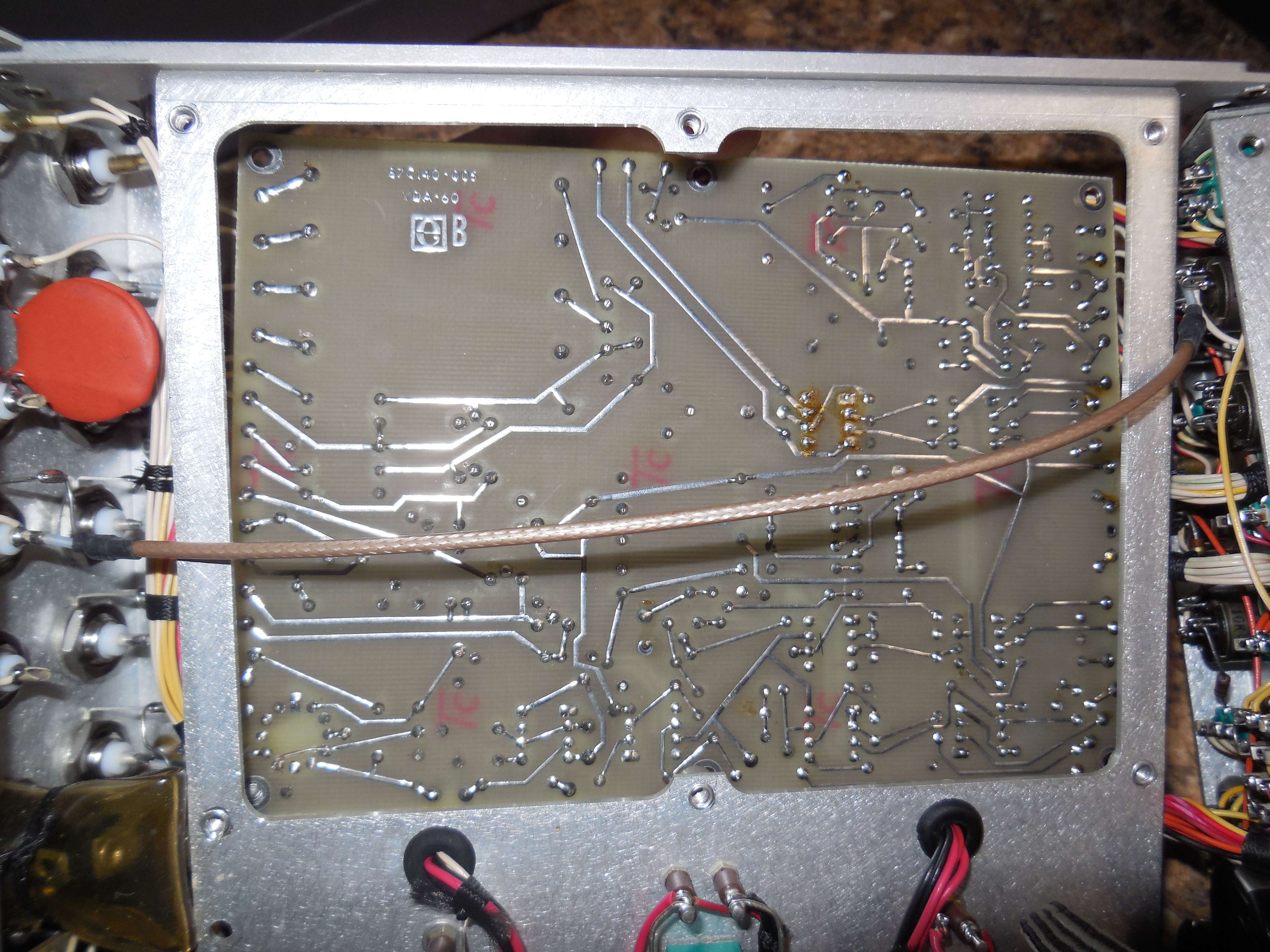
Micro-Tel Corporation VDA-60 Video Display Analyzer Ser. 177 PCB: 87C140-005 / VDA-60 A1B4 U18 = LM320T-12 (-12V) U17 = LM340AT12 (+12V) U16 = 7806 (+6V) U15 = 7918 (-18V) U14 = 7818 (+18V) U13 = RCA CA3023 (video amplifier, 44 dB, DC-10 MHz) U12 = Signetics NE555 (555 timer) U11 = 7805 (+5V) U10 = National 74LS122 (retriggerable multi-vibrator / TDR) U9 = National LM555 (555 timer) U8 = 7906 (-6V) U7 = RCA CA1458 (general dual op-amp) U6 = RCA CA555 (555 timer) U5 = Unk. LM741 (general op-amp) U4 = National LM741 (general op-amp) U3 = RCA CA3080A (transconductance amplifier / multiplier) U2 = SK9144 (replacement, original unknown - high-speed op-amp) U1 = RCA CA3080A (transconductance amplifier / multiplier) Q1 = 2N3904 (NPN) Q2 = 2N3904 (NPN) Q3 = 2N3906 (PNP) Q4 = 2N2905 (PNP / TDR) Q5 = 2N2270 (NPN / TDR) E6 = COAX -> RASTER - IN - BNC E7 = WHITE (RASTER = VIDEO POS/NEG Switch - CENTER) E8 = WHITE (RASTER = SYNC POS/NEG Switch - CENTER) E9 = WHITE w/ ORANGE (RASTER = VIDEO POS/NEG Switch - POS Position Enabled) E10 = WHITE w/ YELLOW (RASTER = VIDEO POS/NEG Switch - NEG Position Enabled) E11 = WHITE (RASTER = VIDEO LEVEL Pot - WIPER) E12 = LAVENDER (-6V for FREQ/LEVEL Pots) E13 = COAX -> RASTER - VIDEO - BNC E14 = RED w/ PINK (+18V? - Switched) E15 = YELLOW w/ WHITE (-18V? - Switched) E16 = WHITE w/ BROWN (RASTER = SYNC POS/NEG Switch - POS Position Enabled) E17 = WHITE w/ RED (RASTER = SYNC POS/NEG Switch - NEG Position Enabled) E18 = WHITE (RASTER = SYNC LEVEL Pot - WIPER) E19 = COAX -> RASTER - SYNC - BNC (No shield/ground connection on BNC connector) E20 = WHITE /w GREEN (RASTER = VERT - TV Position Enabled) E21 = WHITE (RASTER = VERT Switch - CENTER) E22 = WHITE w/ ORANGE (RASTER = VERT - RASTER Position Enabled) E23 = WHITE (RASTER = VERT FREQ Pot - WIPER) E24 = WHITE -> RASTER - VERT - BNC E25 = RED (+12V - Switched) E26 = ORANGE (+6V - Switched) E27 = YELLOW (-12V - Switched) E28 = Ground E29 = WHITE w/ GREEN (TDR = HI/LO Switch - HI Position Enabled) E30 = WHITE (TDR = HI/LO Switch - CENTER) E31 = WHITE (TDR = HI/LO Switch - CENTER) E32 = WHITE w/ GREEN (TDR = HI/LO Switch - HI Position Enabled) E33 = WHITE w/ BLUE (TDR = HI/LO Switch - LO Position Enabled) E34 = RED (+12V for TDR - Switched) E35 = WHITE (Input wire to the TDR BAL and Z pots) E36 = WHITE (SYNC = FREQ Pot - Terminal 1 & 2) E37 = WHITE w/ BLUE (SYNC = FREQ Pot - Terminal 3) E38 = WHITE -> SYNC OUT - BNC E39 = ORANGE (+6V to SYNC switch) E40 = COAX <- VIDEO - IN - BNC (Input for CA3023 video amp) E41 = ORANGE (+6V - Switched for CA3023 Video Amp) E42 = COAX -> VIDEO - OUT - BNC (Output of CA3023 video amp) E43 = WHITE w/ GREY (Transformer Input - 120 VAC NEUTRAL) E44 = WHITE (Transformer Input - 120 VAC LIVE - Fuse) E45 = WHITE (Transformer Input - 120 VAC LIVE - Fuse) E46 = WHITE w/GREY (Transformer Input - 120 VAC NEUTRAL) E47 = Output of bridge rect., which is input to U14, but through 1.2 kΩ R57 E48 = RED w/ PINK (+18V) E49 = YELLOW w/ WHITE (-18V) E50 = Output of bridge rect., which is input to U15, but through R58 E51 = RED w/ PINK (+18V input to U17 [+12V]) E52 = YELLOW w/ WHITE (-18V input to U18 [-12V]) E53 = YELLOW (-12V) E54 = RED (+12V) E55 = ORANGE (+6V) R12 = 51Ω R13 = 510Ω R14 = 5.1 kΩ R15 = 51.0 kΩ R16 = 51Ω R17 = 1.0 kΩ R18 = 1.0 kΩ R19 = 12.0 kΩ R20 = 3.3 kΩ R21 = 3.3 kΩ R22 = 82.0 kΩ R23 = 1.0 kΩ R24 = 1.0 kΩ R25 = 12.0 kΩ R26 = 5.1 kΩ R27 = 24.0 kΩ R28 = 5.1 kΩ R29 = 1.0 MΩ R30 = 10.0 kΩ R31 = 1.0 MΩ R32 = 10.0 kΩ R33 = 10.0 kΩ R34 = 10.0 kΩ R35 = 20.0 kΩ R36 = 10.0 kΩ R37 = 3.3 kΩ R38 = 4.7 kΩ R39 = 4.7 kΩ R40 = 10.0 kΩ R41 = 2.4 kΩ R42 = 30.0 kΩ R43 = 82.0 kΩ R44 = 2.7 kΩ R45 = 2.7 kΩ R46 = 2.7 kΩ R47 = 2.0 kΩ R48 = 2.7 kΩ R49 = 820Ω R50 = 200Ω R51 = 820Ω R52 = 200Ω R53 = 51Ω R54 = 51Ω R55 = 2.0 kΩ R56 = 4.7 kΩ R57 = 1.2 kΩ R58 = 1.2 kΩ SYNC - FREQ = 100 kΩ Clarostat 73JA 5% LIN .25% 10-turn DC OFFSET - LEVEL = 10 kΩ Clarostat 73JA 5% LIN .25% 10-turn VERT - FREQ = 10 kΩ Clarostat RV6NAYSD103A SYNC - LEVEL = 10 kΩ Clarostat RV6NAYSD103A VIDEO - LEVEL = 10 kΩ Clarostat RV6NAYSD103A TDR - Z = 1 kΩ Clarostat RV6NAYSD102A TDR - BAL = 500Ω Clarostat RV6NAYSD501A C1 = 470 pF / Silver Mica / 5% C2 = 20.0 µF / 50V / Non-Polarized C3 = 20.0 µF / 50V / Non-Polarized C4 = 6.8 µF / KEMET C5 = 6.8 µF / KEMET C6 = 0.001 µF / 100V / Poly C7 = 1.0 µF / 50V / Poly C8 = 0.0022 µF / 100V / Poly C9 = 0.001 µF / 100V / Poly C10 = 1.0 µF / 50V / Poly C11 = 0.01 µF / 100 / Z5U CER C12 = 10.0 µF / KEMET C13 = 2.2 µF / 20V / KEMET C14 = 22.0 µF / KEMET C15 = 10.0 µF / KEMET C17 = 0.01 µF / 100 / Z5U CER C18 = 0.1 µF / CER C19 = 27 pF / Silver Mica / 270J03 - CM05ED C20 = 270 pF / Silver Mica / 271J03 - CM05FD C21 = 200 pF / Silver Mica / 201J03 - CM05FD C22 = 820 pF / Silver Mica / 5% C23 = 2.2 µF / KEMET C24 = 0.22 µF / Poly C25 = 0.0015 µF / 100V / 10% Poly C26 = 0.01 µF / 100 / Z5U CER C27 = 22.0 µF / KEMET C28 = 20.0 µF / 50V / Electrolytic C29 = 0.01 µF / 100 / Z5U CER C30 = 2.2 µF / KEMET C31 = 0.01 µF / 100 / Z5U CER C32 = 50.0 µF / 50V / Electrolytic C33 = 0.22 µF / Poly C34 = 0.1 µF / CER C35 = 50.0 µF / 50V / Electrolytic C36 = 2.2 µF / KEMET C37 = 1.0 µF / KEMET C38 = 0.1 µF / CER C39 = 0.22 µF / Poly C40 = 0.22 µF / Poly C41 = 2.2 µF / KEMET C42 = 2.2 µF / KEMET DA1 = Semtech SBEB1 Bridge Rectifier All other diodes appear to be 1N4001 type. T1 = AC Transformer / Unknown / 481-8102 / F44-017-F-N |
VDA-60 Schematics
May not be accurate.
- Micro-Tel VDA-60 Video Display Analyzer - Schematic #1 Main sections. (Raw Schematic)
- Micro-Tel VDA-60 Video Display Analyzer - Schematic #2 Wiring for the power supply, AC input and transformer.
- Micro-Tel VDA-60 Video Display Analyzer - Schematic #3 Wiring diagram of the rear panel.
- Micro-Tel VDA-60 Video Display Analyzer - Schematic #4 Wiring diagram for the TDR section.
- Micro-Tel VDA-60 Video Display Analyzer - Schematic #5 Wiring diagram for the front panel.
Pictures
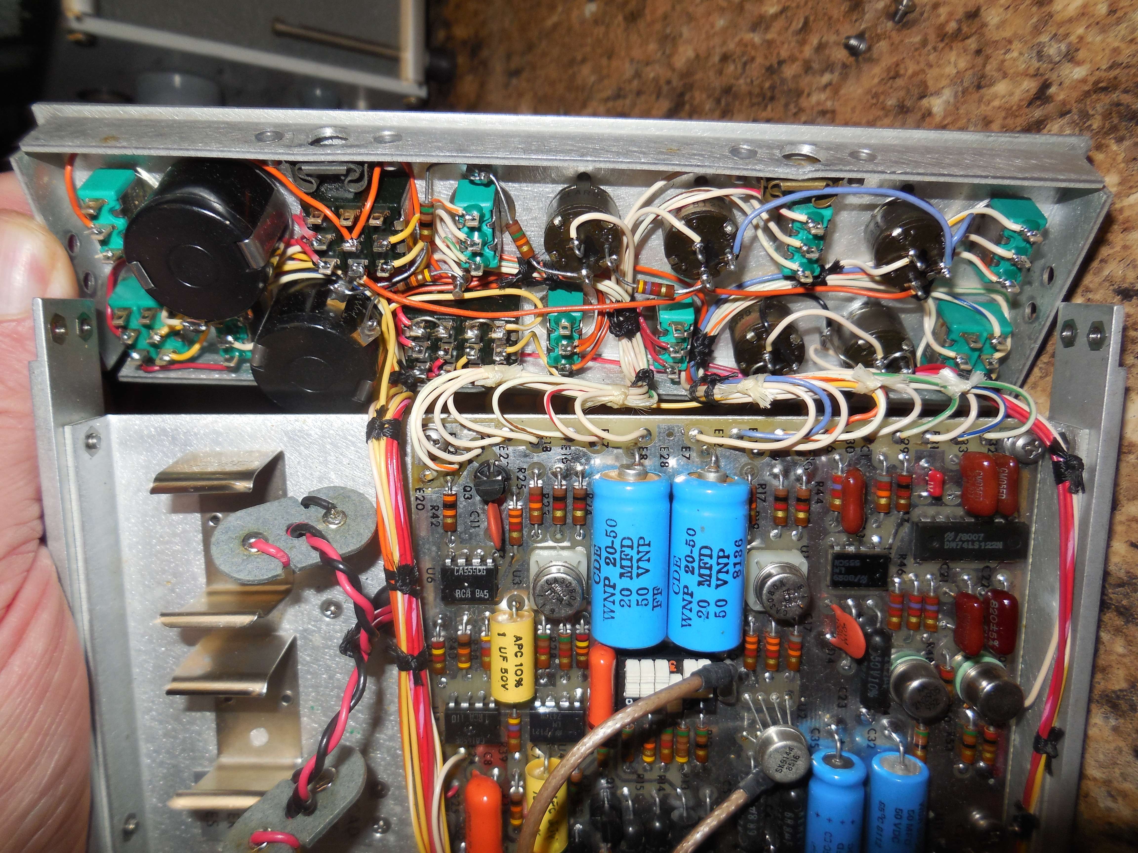
U2 was clearly replaced with a SK9144 op-amp in my unit. I don't know what the original part was, but probably a LM741 or equiv.
The DIP switch selects different resistors to be switched in/out/parallel on the VIDEO INPUT signal.
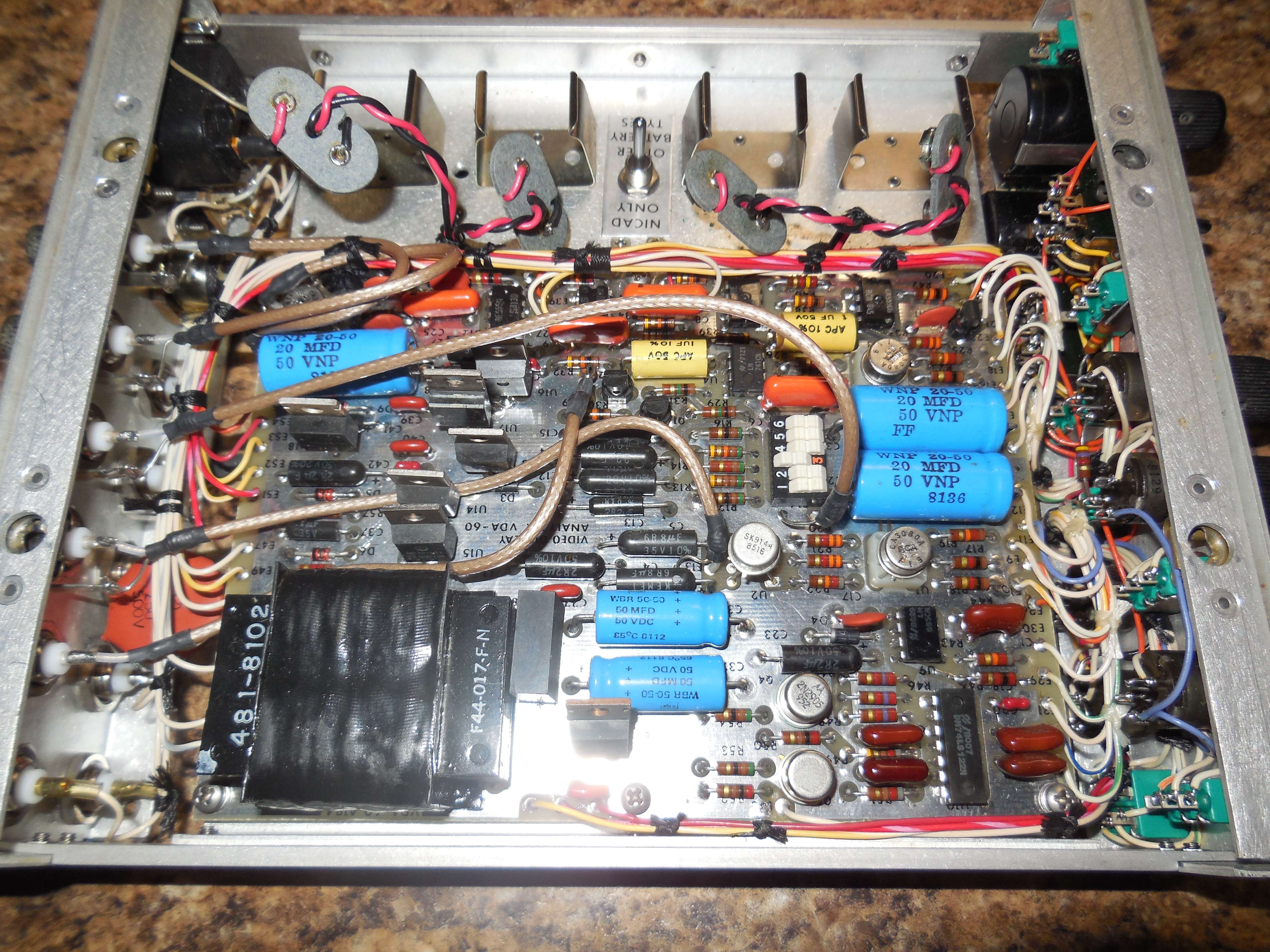
The CA3023 appears to be setup as a stand-alone video signal amplifier, with VIDEO IN/OUT connection on the rear panel.
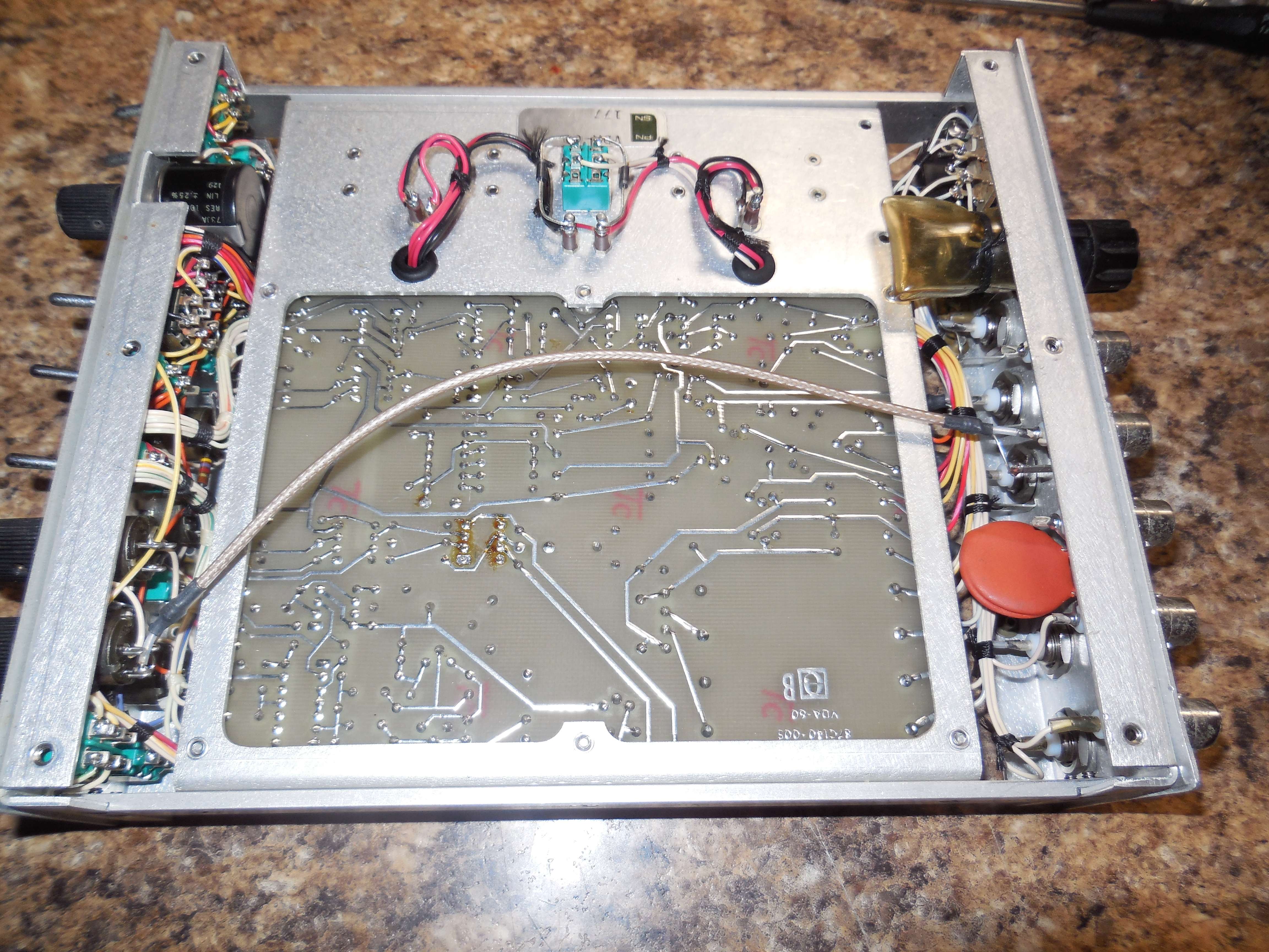
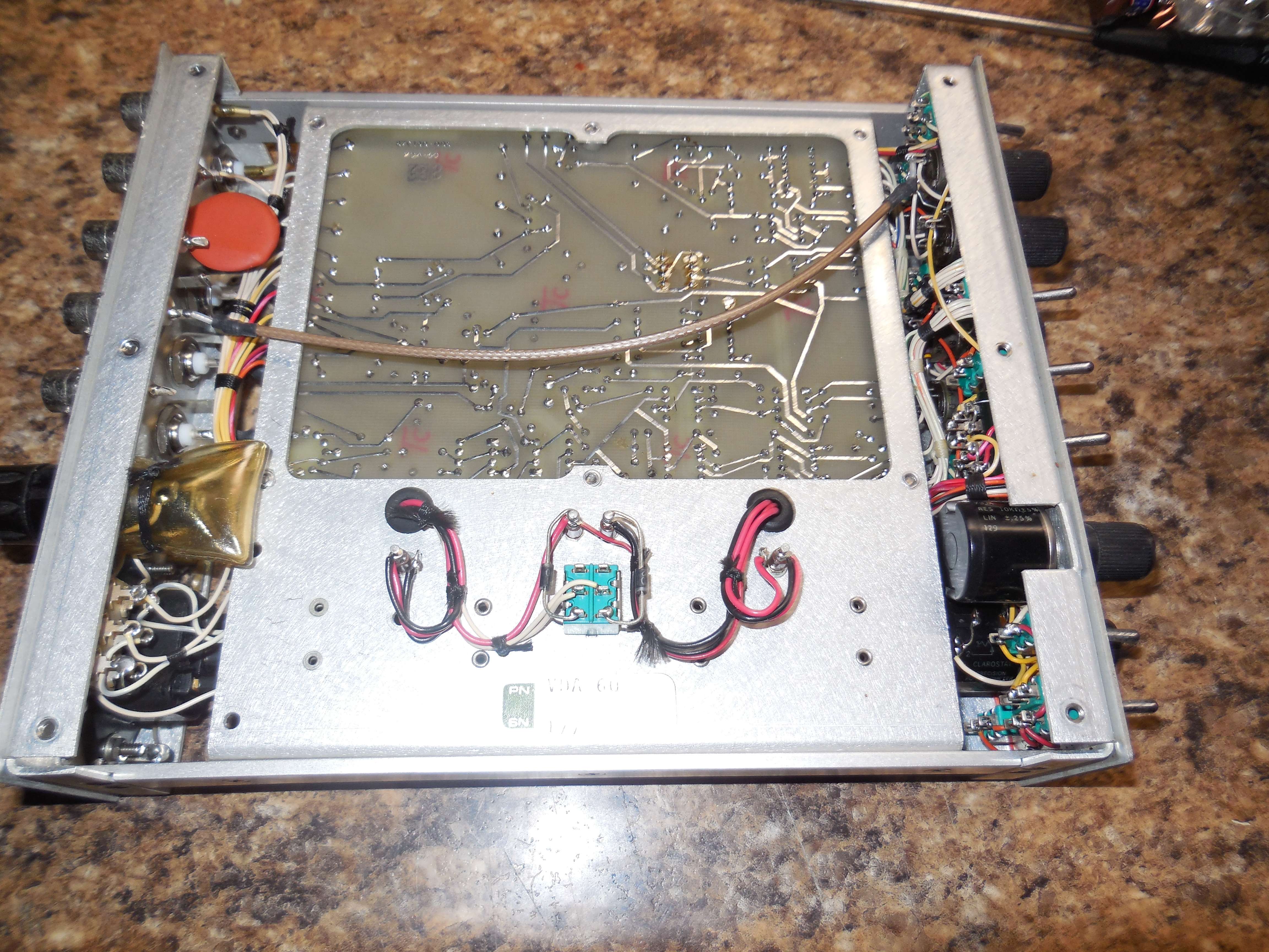
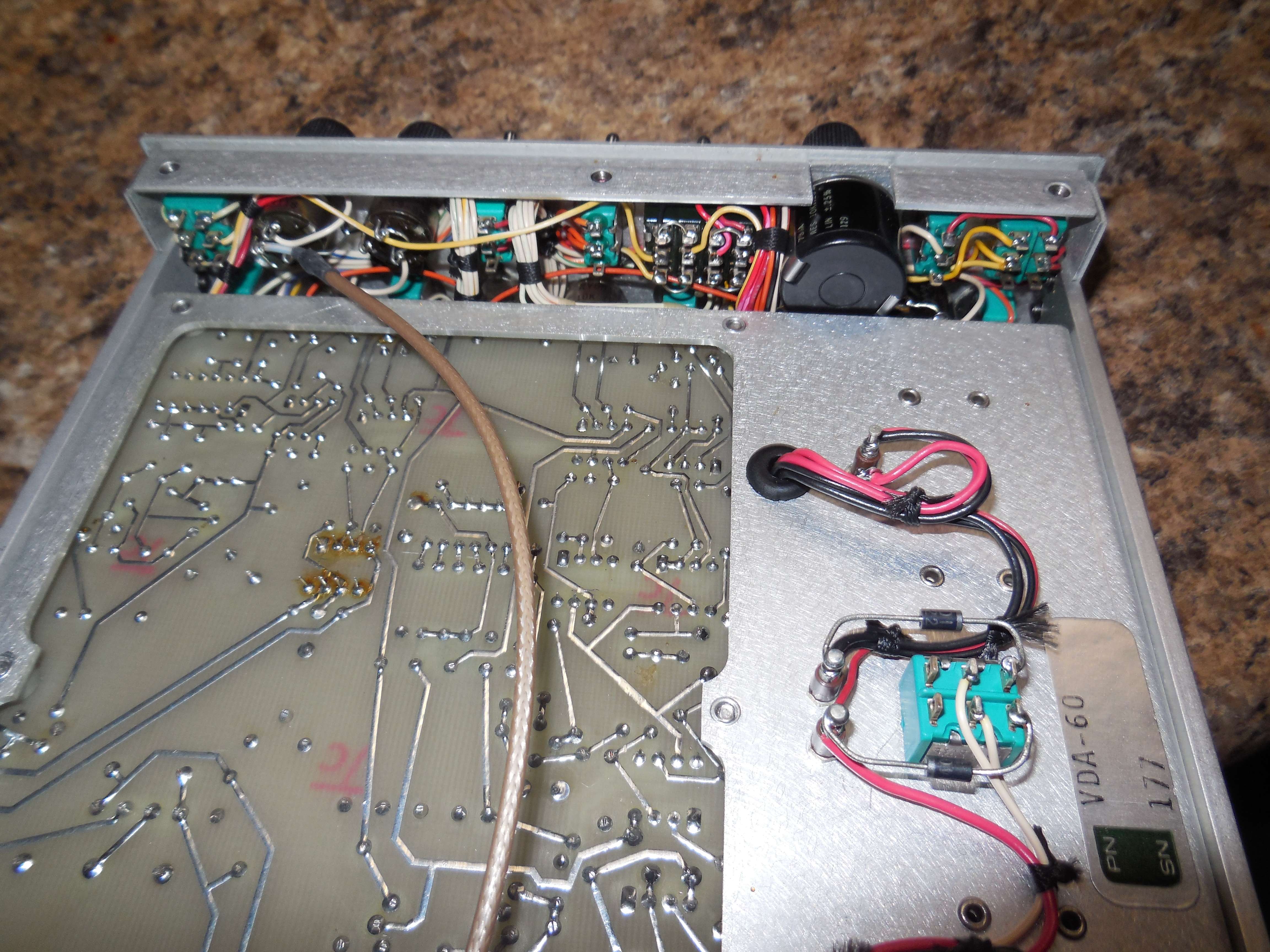
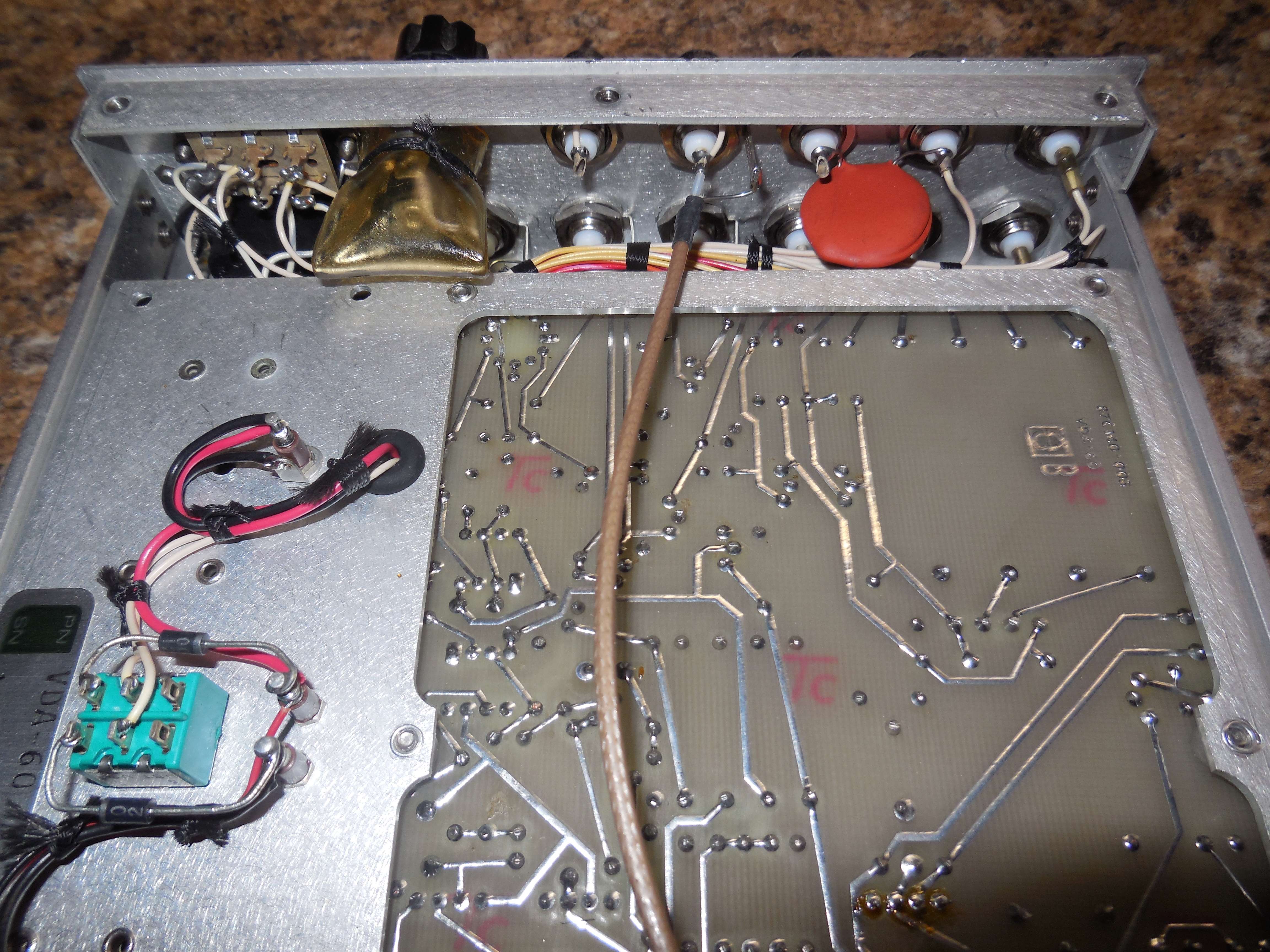
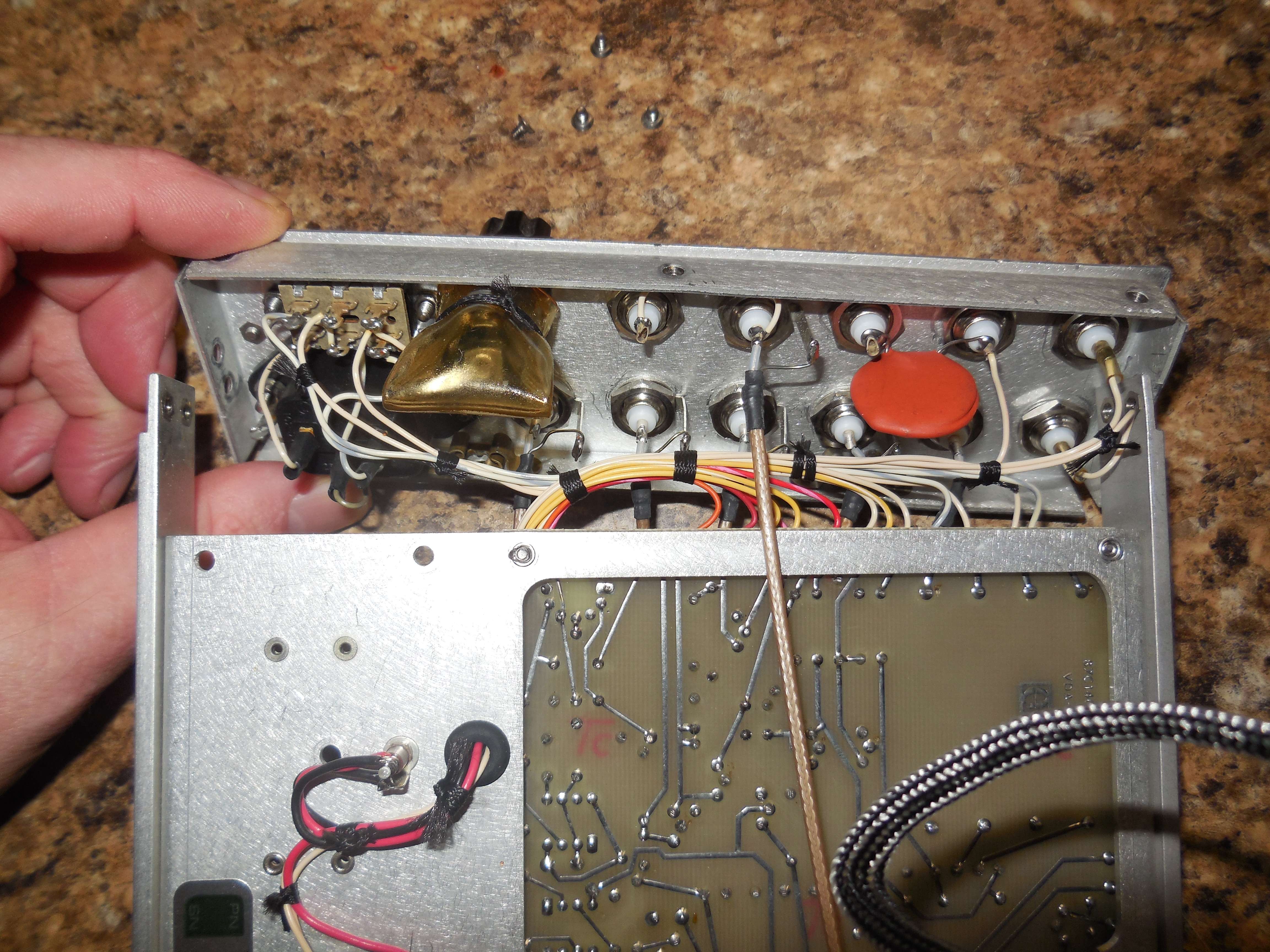
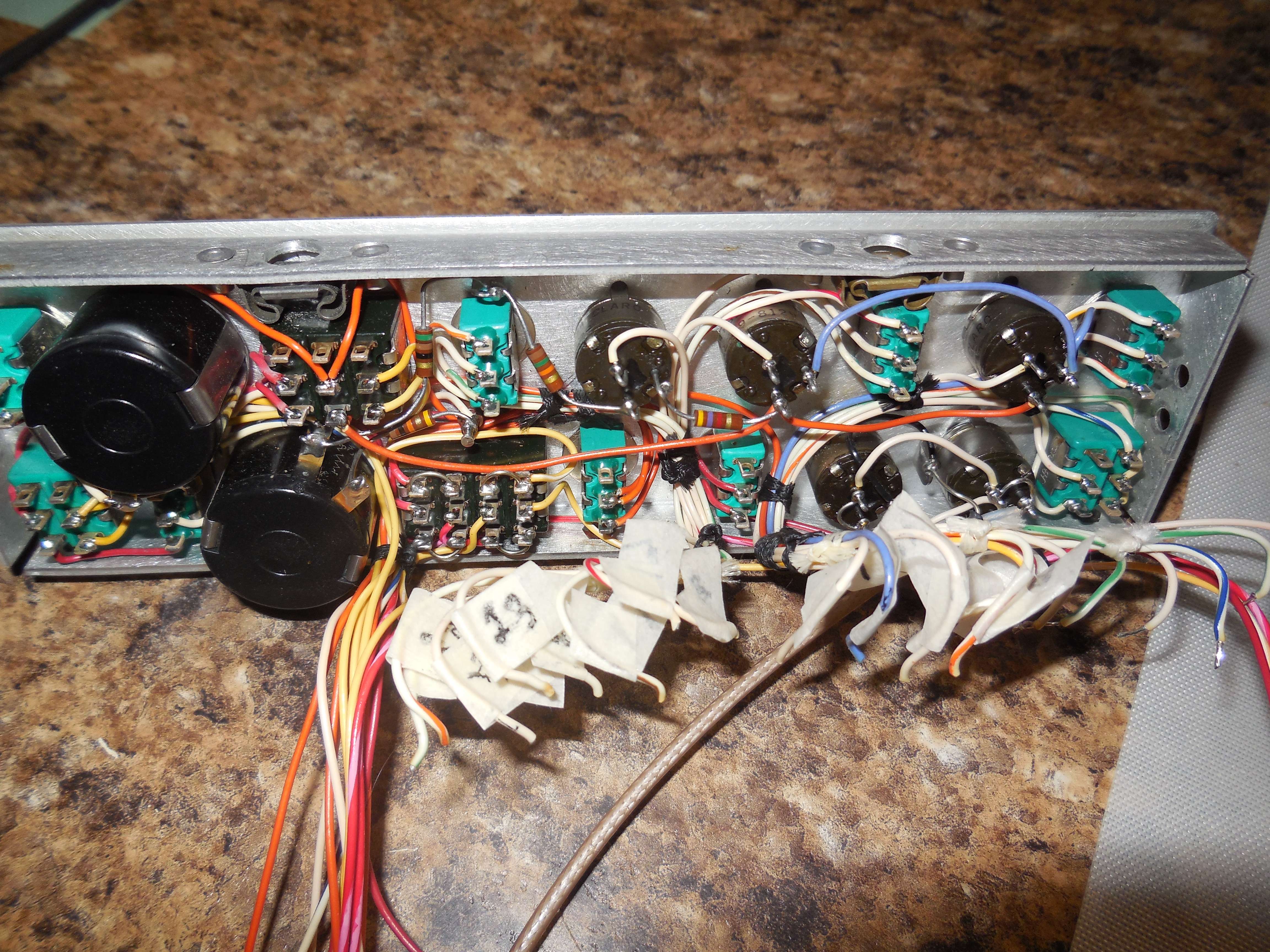
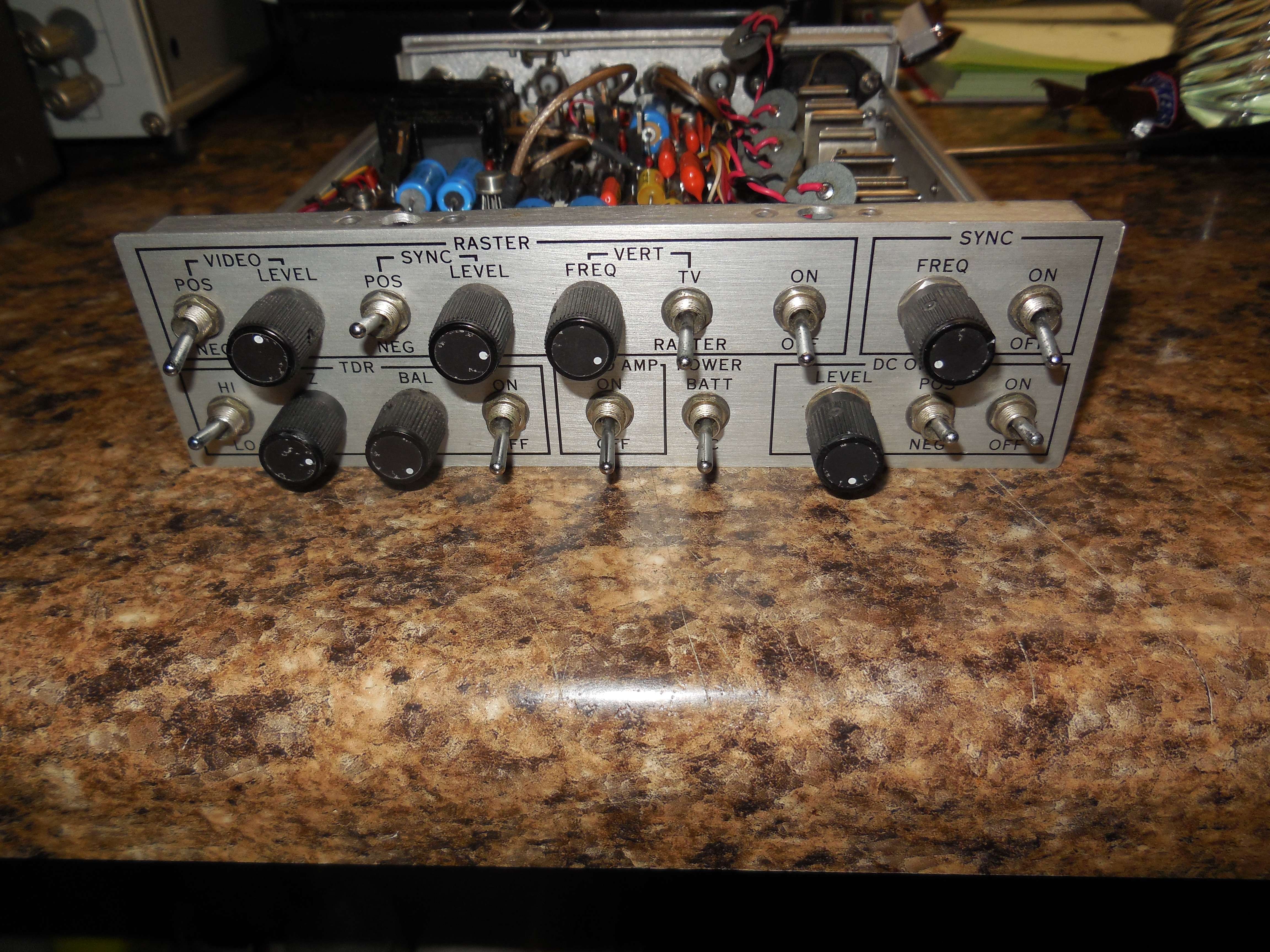
Rear view (internal) of the front panel.
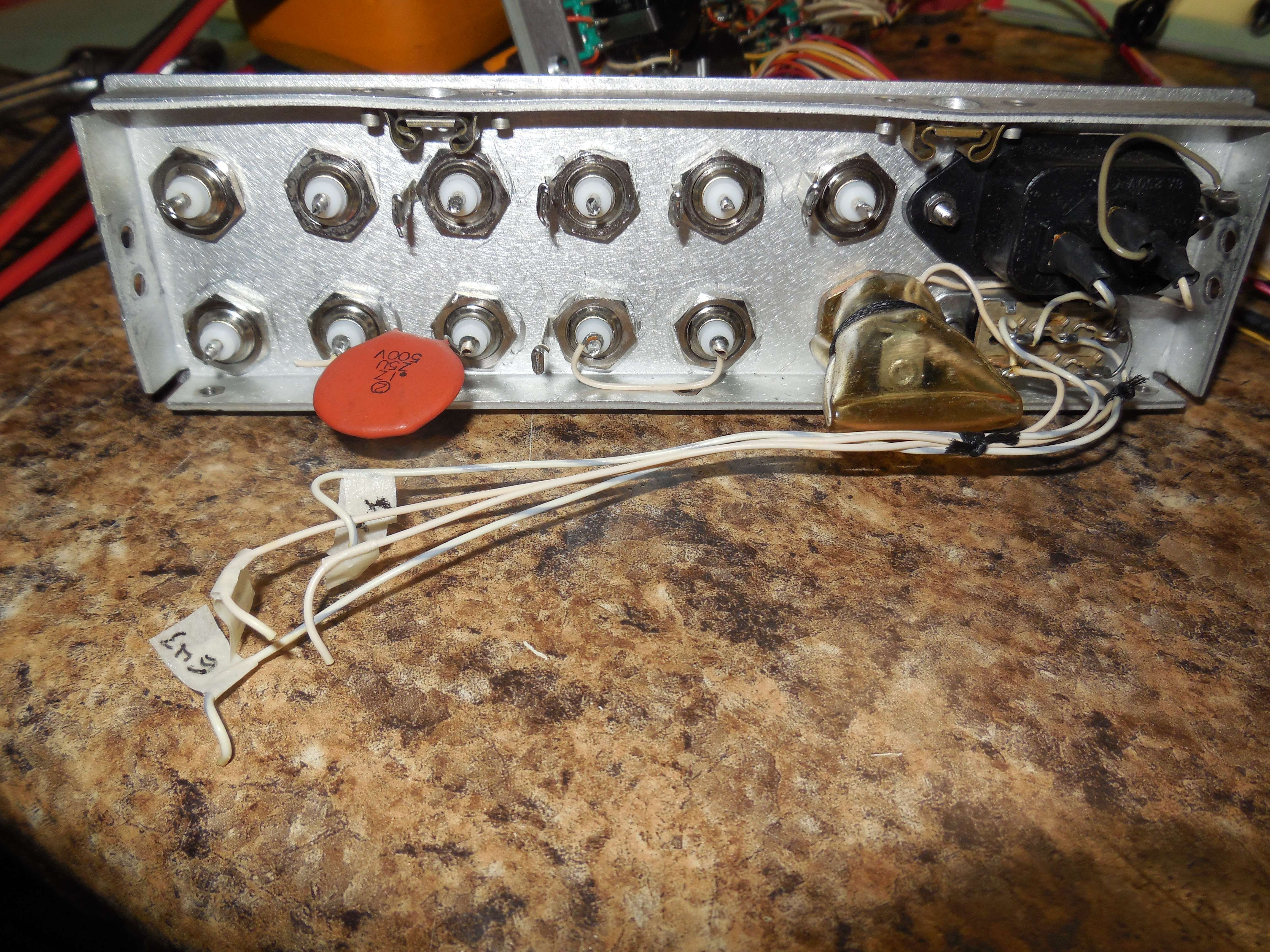
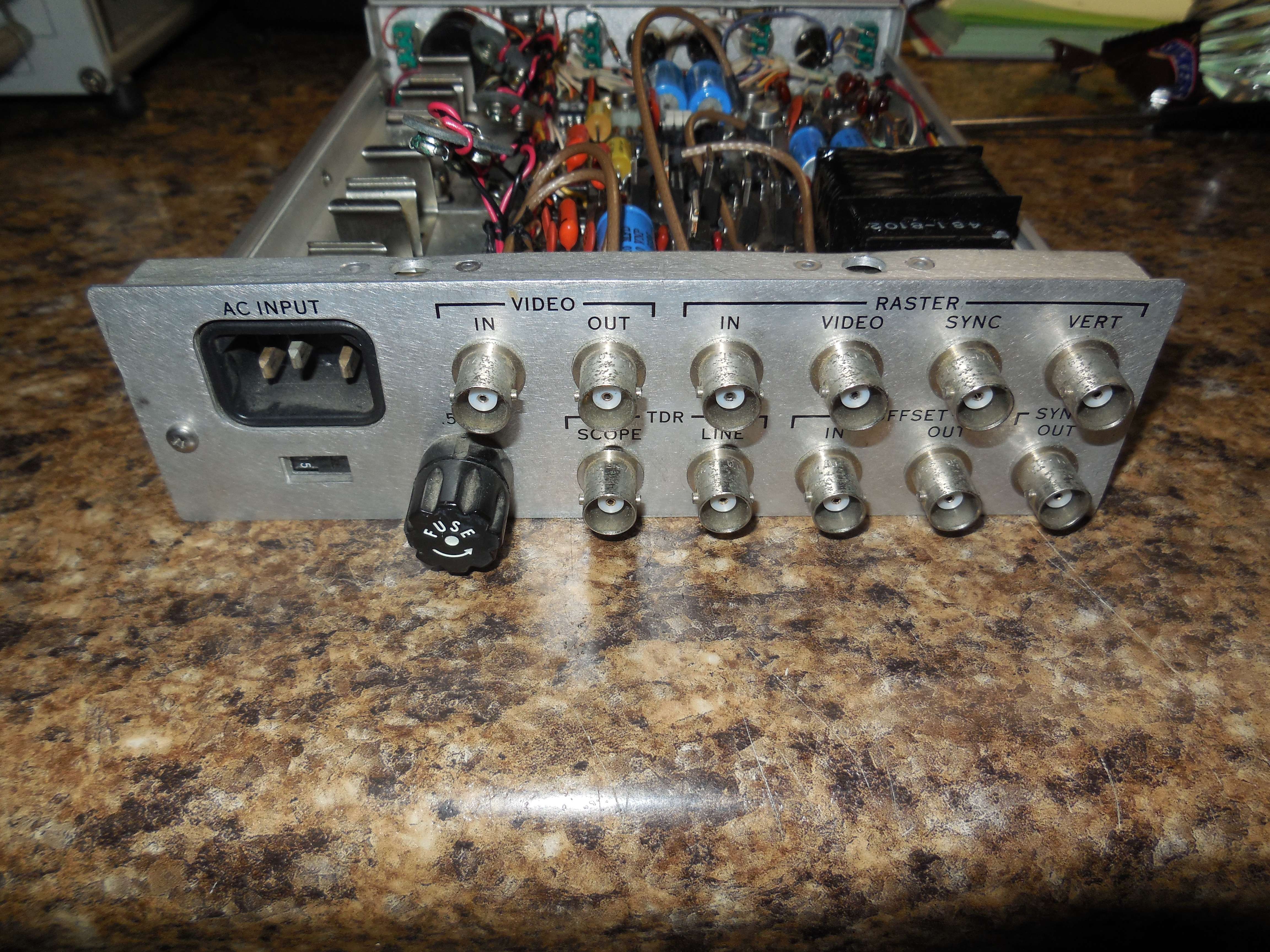
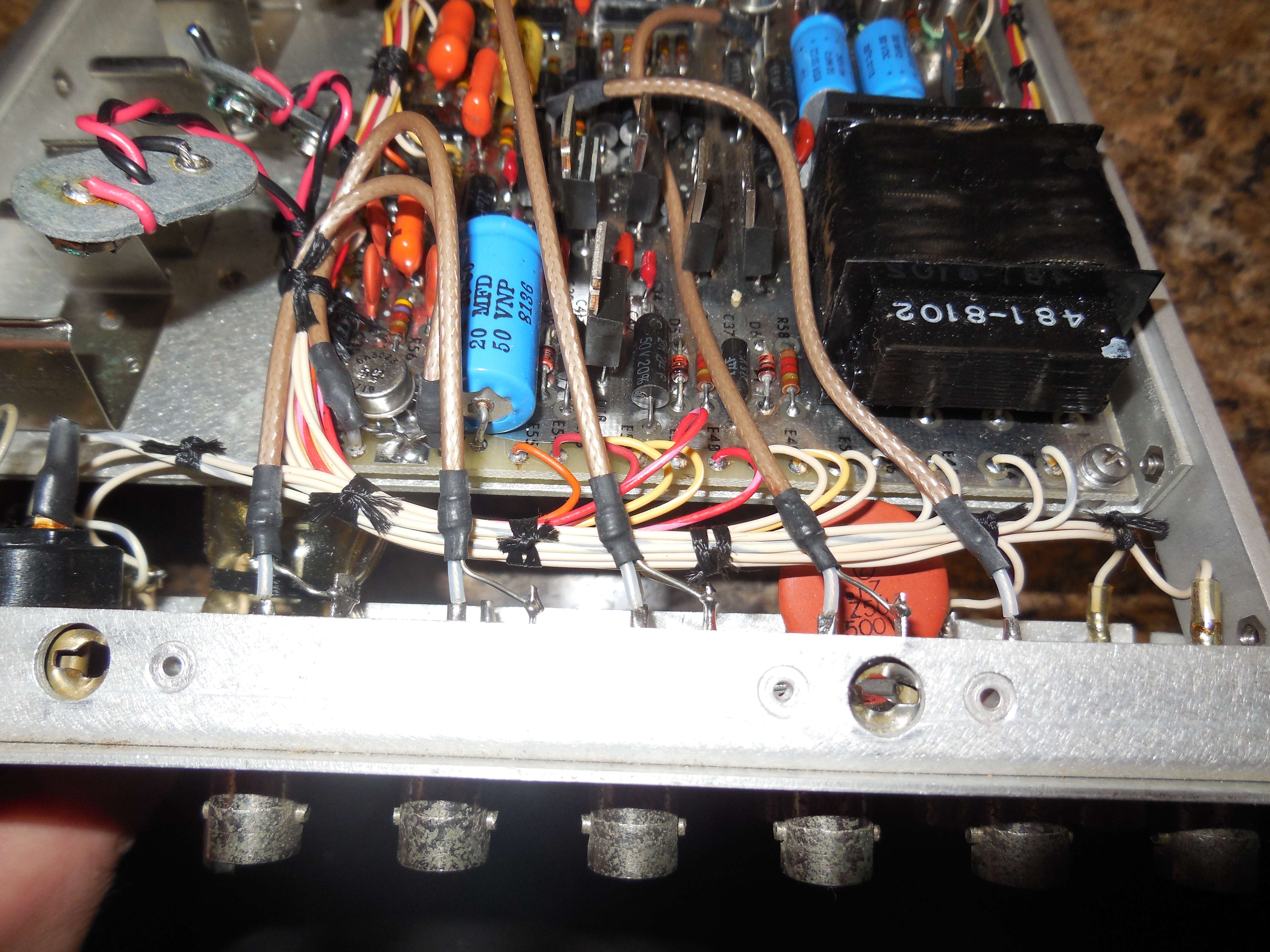
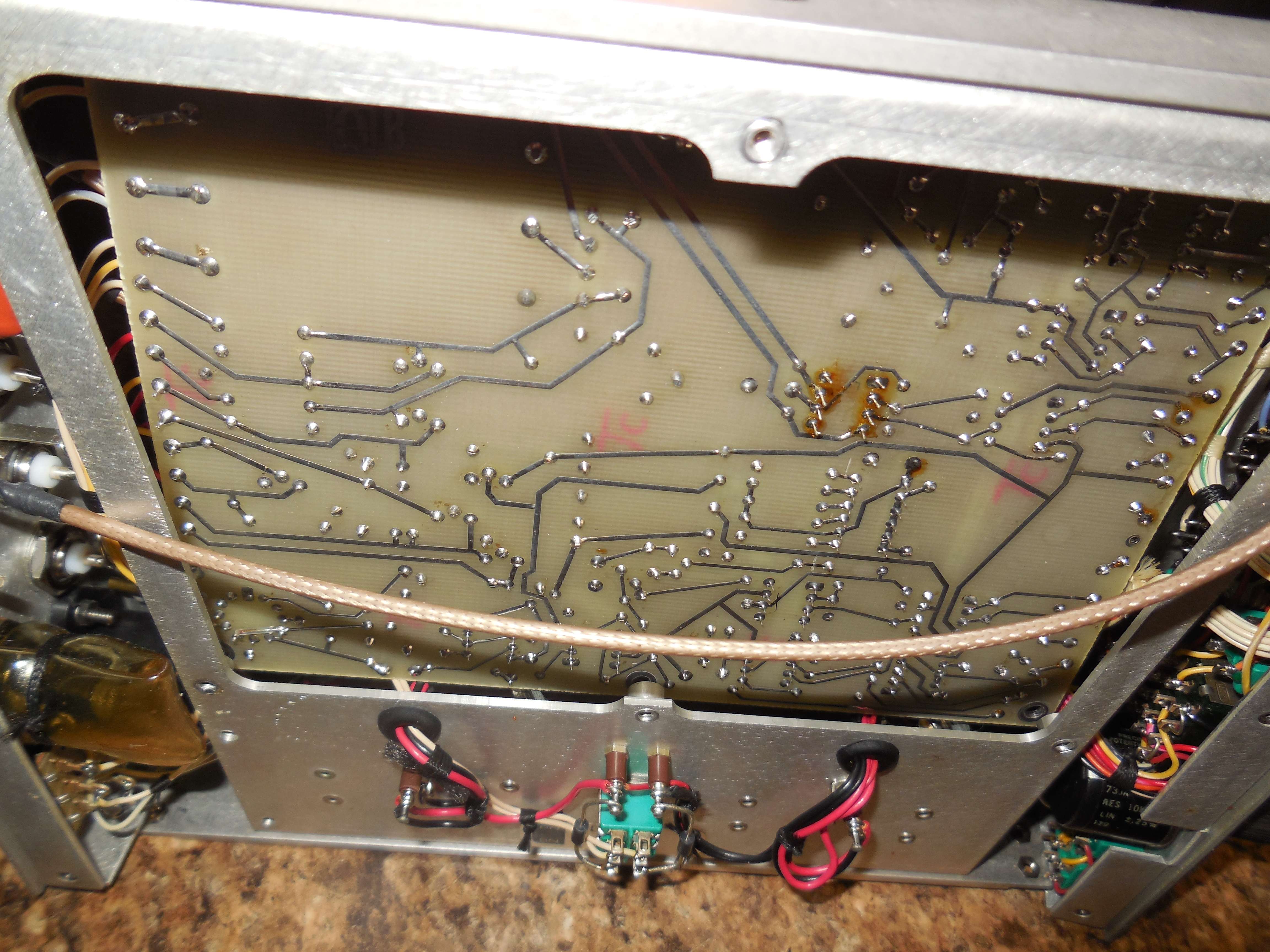
Rear view (internal) of the back panel.
It is fairly easy to raise a rasterized signal on any oscilloscope so long as you can squirt a Z-axis into the scope, and then set up the X and Y axis from some kind of external raster timing generator. This is lot limited to video signals however, and can be applied to a wide variety of digital and analog signals, a good example being the use of raster generators to hunt down the timing of digital or multi-level/gray level signals. Virtually anything with a repeating sequence, data streams, encrypted phones, etc can be examined, and you can resolve at least some limited parameters while perhaps not reconstructing the signal. Also, very often the signal coming off your receiver has to have the signal levels adjusted to a usable amplitude, or as you say the polarity, but we also have to be sensitive to the making sure the scope has enough bandwidth to "draw" the raster, but also a fast enough phosphor (but not too fast) so you can actually see the image. With some of the newer PC based TV receivers such as WinTV you can actually use the card to sample the suspect video and then adjust the image timing and reconstruct the images right to the hard drive. A quick and dirty way to do this is to simply apply the output from your radio to a RF modulator, and the feed the RF signal (usually channel 2, 3 or 4) into the WinRadio card as it adjust the amplitude for you but you have to give it a signal of the correct polarity. Remember that over-the-air video will be one polarity, and the opposite polarity for conducted video. But, either way it is CRITICAL that you measure the signal to determine what polarity it is using, and then perform some basic time domain measurements. Then take these time domain measurement, drop them into the WinTV software, and be amazed as you image starts to show up. It is normal for the image to roll as you will usually have an imperfect sync lock. Most modern spectrum analyzers such as the ESA and PSA actually have video capabilities where you can define the time of a signal, then set both the video line sync, and amplitude triggers so that you can obtain a perfectly sync'ed image. If you try this you could get it to work with a scope with only a few MHz of bandwidth, but something with a bandwidth of over 25 MHz is best, and over 50 MHz is better yet. -jma |