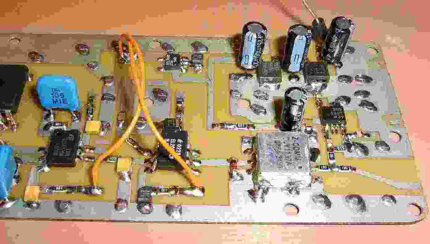
Constructing the 1.25 GHz phase-locked loop oscillator board.
The Z-Comm CLV1137 is the silver square on the lower-right. The 8-pin SMT chip next to it is the Fujitsu MB506 prescaler. The 8-pin DIP chip to the left of the CLV1137 is an EL2020 wide-bandwidth op-amp. To the left of that, is a MC33171 low-power op-amp for the PLL loop filter.
On the upper-right are the 78M05 and 78M12 voltage regulators. The 8-pin SMT chip to the left of the voltage regulators is an ICL7660 negative voltage regulator for powering the op-amps.
The EL2020 op-amp isn't really needed for this converter project, but it will allow you to modulate the VCO if you should ever require. A wide-bandwidth op-amp like the EL2020 also isn't necessary unless you plan to modulate the VCO with a video signal.
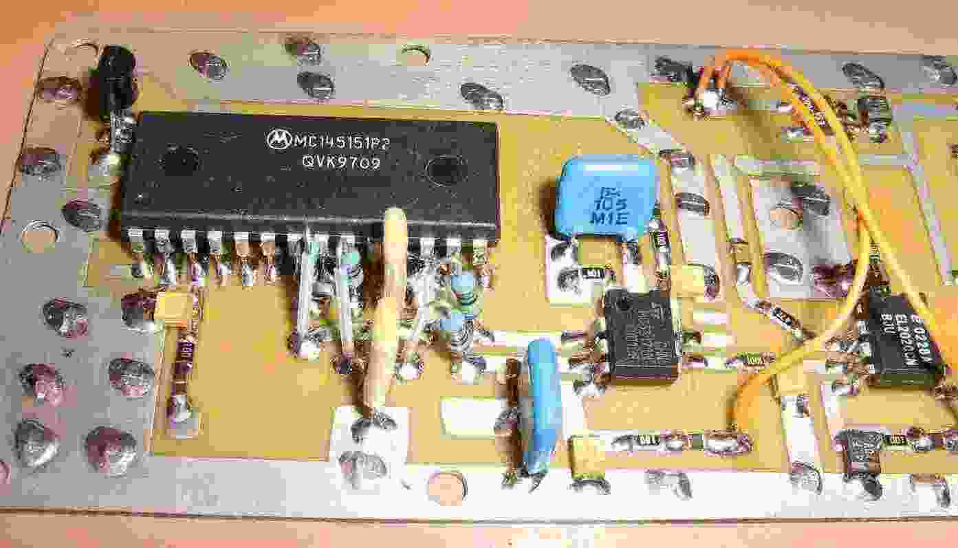
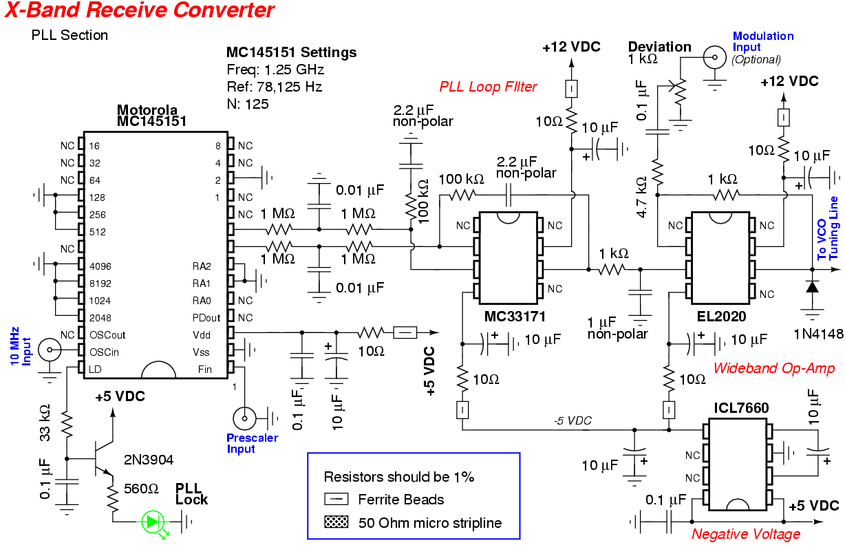
Overview of the Motorola MC145151 PLL circuitry.
The passive components for the MC145151's loop filter are shown just below the MC145151.
The 2N3904 transistor on the upper-left is for controlling a "PLL Lock" LED.
For this converter project, the MC145151 will be using an external 10 MHz Temperature-Compensated Crystal Oscillator (TCXO) for generating the MC145151's reference frequency (78,125 Hz).

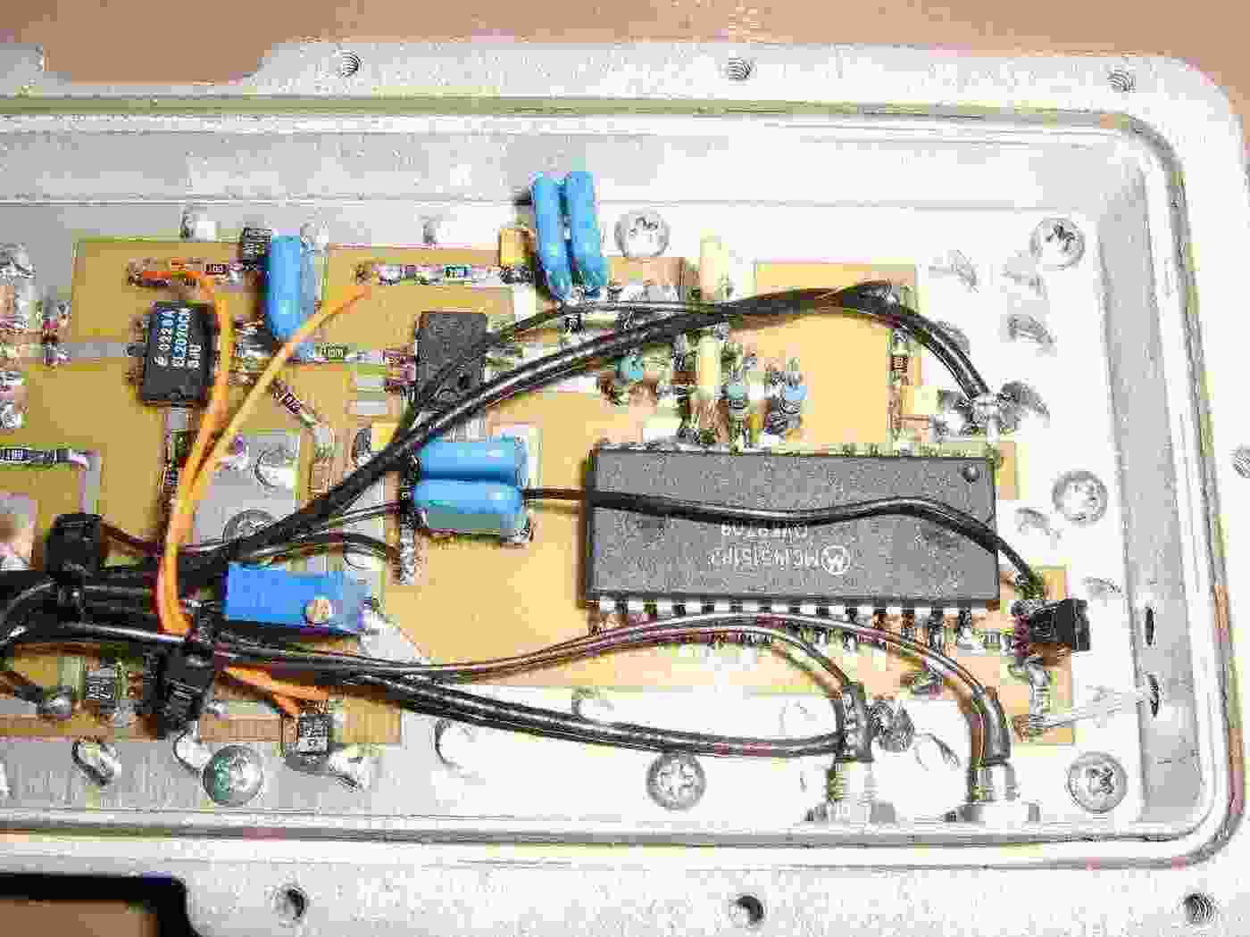
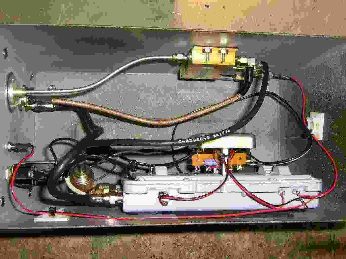
Overview of the completed 1.25 GHz phase-locked loop oscillator board.
The blue multiturn potentiometer in the middle is for adjusting the deviation of any optional modulating signal.
There are two feed-through capacitors (lower-right) for supplying clean +12V and +5V for the TCXO and HMC444 evaluation board.
Note that the pictures and schematic of this oscillator board will vary due to constant tweaking. The schematic will have the correct component values.

Closeup view of the completed 1.25 GHz phase-locked loop oscillator board.
Main +15V DC input to the board is via a feed-through capacitor (lower-left).
The RF output (upper-left) is via a N connector.
The external 10 MHz signal for the MC145151 input (middle-left) is via a BNC connector.
Modulation input (lower-left) is via a F connector.
The final RF output of this oscillator was -5 dBm.
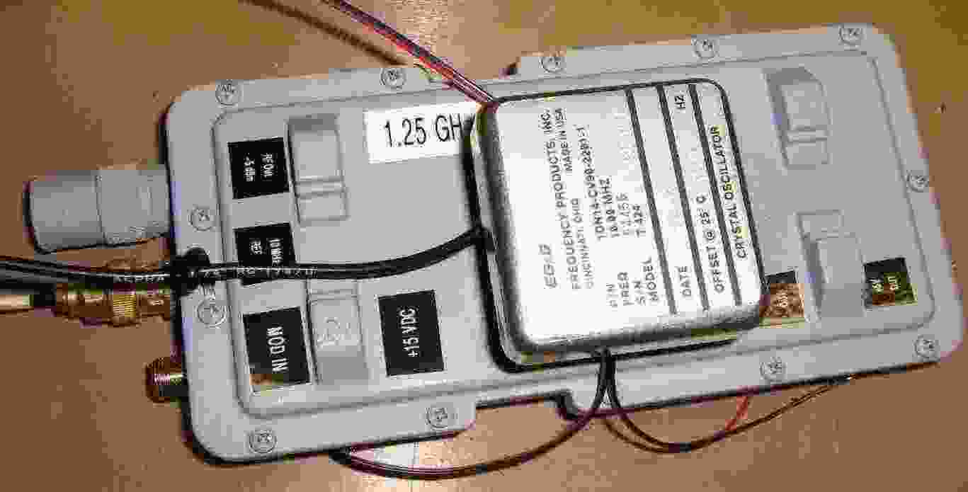
Closeup view of the completed 1.25 GHz phase-locked loop oscillator board.

External 10 MHz TXCO crystal reference oscillator.
It is a EG&G Frequency Products, Inc. model T424 and was from an old Qualcomm OmniTRACS satellite fleet tracking system.
The TCXO just needs a source of +12V and a large bypass capacitor (33 µF or so). The output of the TCXO is via a short piece of coax with a BNC connector.
Any 10 MHz crystal oscillator will do, but remember that any frequency error or noise in the PLL reference frequency will essentially be multiplied 128,000 times.
It's also possible to tune this particular 10 MHz oscillator to within a few Hertz of 10 MHz by zero-beating its signal to WWV.
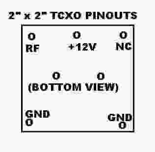
EG&G TCXO Pinout
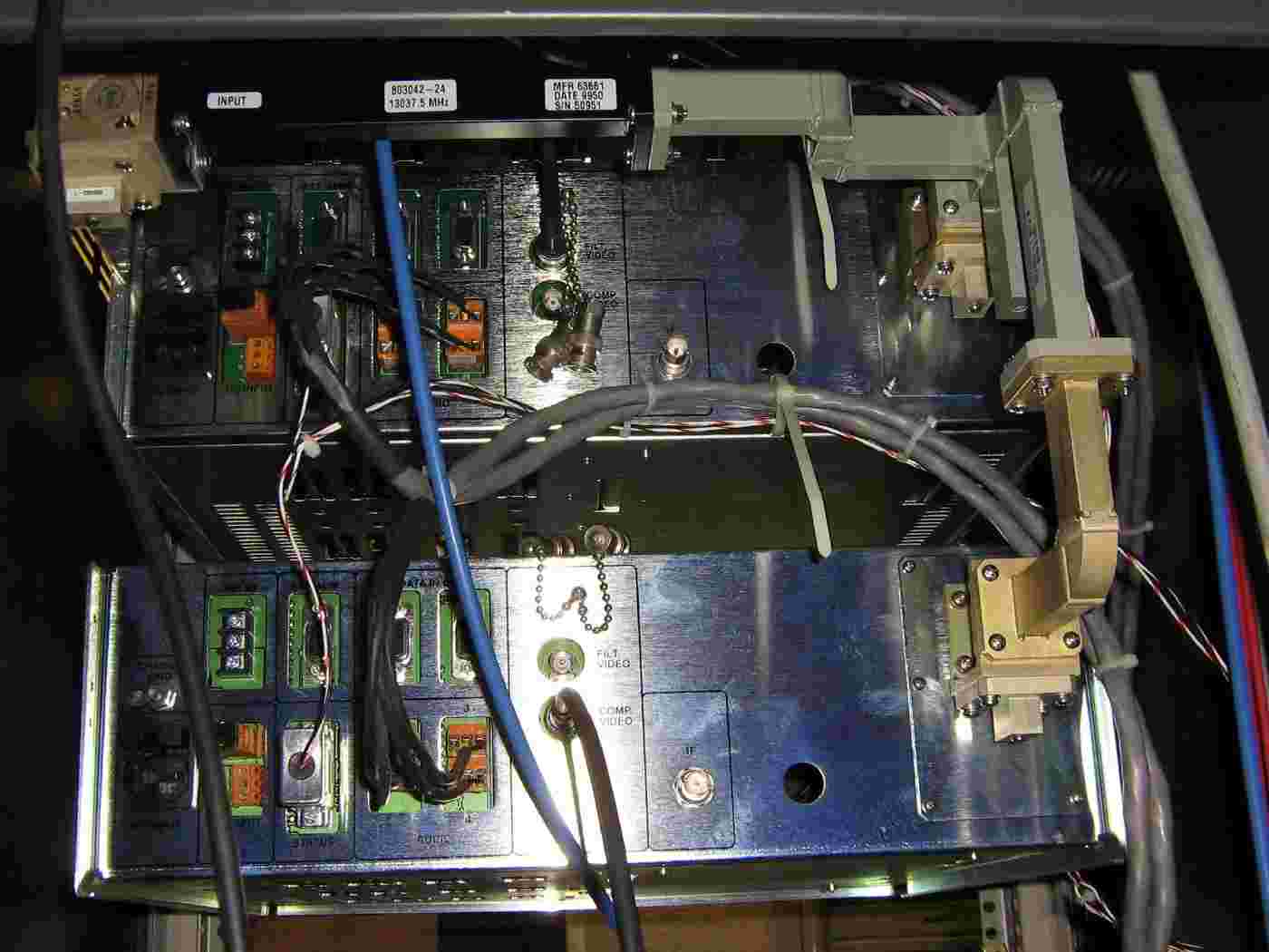
Attaching the external 10 MHz TXCO crystal to the outside of the MMDS downconverter case housing the oscillator board.
The 10 MHz signal is applied to the oscillator board via the gold-colored BNC connection.
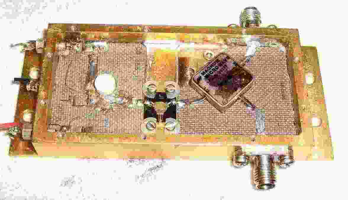
The microwave-range RF mixer for this converter is based around a salvaged Magnum MO64 mixer.
A short piece of conformable coax with a male SMA connector was added for the LO input to the MO64 mixer. This little module's original LO signal was disabled.
The lower female SMA connector is the mixer's IF output.
The upper female SMA connector is the mixer's RF input.
The MO64's specifications are:
       RF Range: 6.0-12.5 GHz
       LO Range: 5.0-15.0 GHz
       IF Range: DC-2.5 GHz
       LO Power: +10 dBm
Conversion Loss: 5.0 dB
Any RF mixer with similar specifications will also work. Note that we'll be running the LO power below the required level, which can increase the mixer's conversion loss. The "RF" and "LO" ports can be interchanged on most mixer models with minimal performance loss.
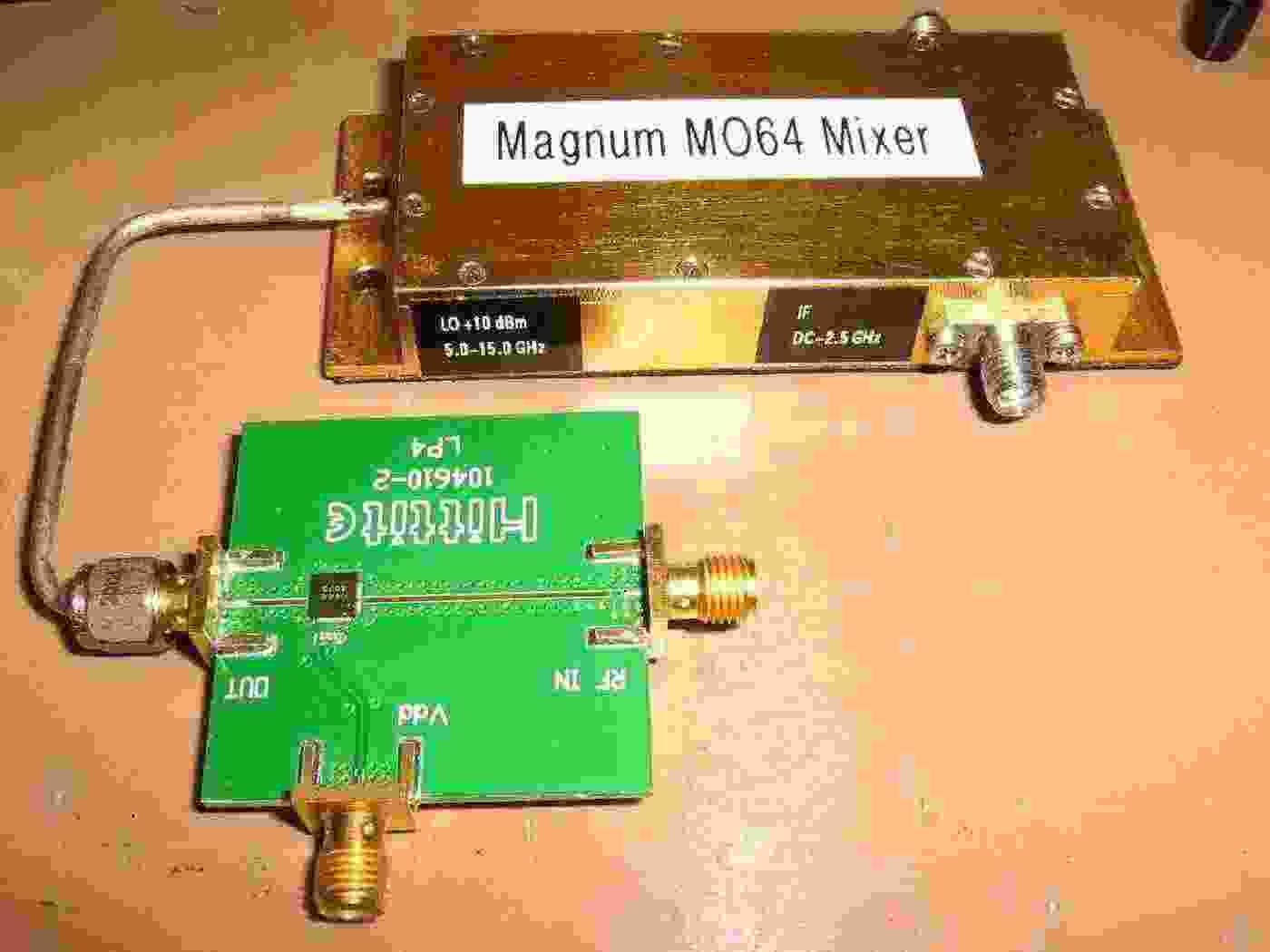
Overview of the Hittite HMC444 evaluation board.
The 1.25 GHz RF input will via the right-side SMA connector and the "multiplied-by-8" 10 GHz RF output will be via the left-side SMA connector.
The SMA connector labeled "Vdd" is for the HMC444's +5 VDC input.

AC power input for the ammo box case we'll be using.
Filtered 120 VAC input goes through a circuit breaker and power switch. This is then applied to a 18 VDC / 200 mA wall-wart power supply which will be powering the oscillator and multiplier circuits.

Mounting the Magnum MO64 mixer and HMC444 evaluation board.
+5 VDC power for the HMC444 active multiplier comes in via the SMA connector on the right-side of the board.
The HMC444 evaluation board has some double-sided foam tape on the bottom of the board to prevent it from flopping around.
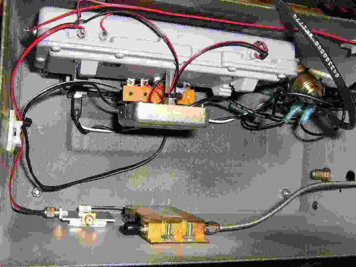
Mounting the 1.25 GHz oscillator module to the side of the case.
Overview of the front-panel and 1.25 GHz oscillator to HMC444 board connections.
A high-quality N connector will be used for the microwave RF input.
A BNC connector is used for the IF output.
A phono jack is used for the modulation input.
A green LED indicates when the PLL is locked.

Finished case overview.
The RF input is via the N connector, which has a protective shell from an old PL-259 connector.
The downconverted IF output is via the BNC connector.
Any (optional) modulation signal for the VCO will be via a phono jack mounted under the BNC connector.
The green "PLL Lock" LED starts out dim when initially powered, but glows brighter when the PLL locks. A "PLL Unlock" LED might have been a better choice.
To operate the converter, apply your X-band or Ku-band RF signal (trying not to exceed 0 dBm) to the RF mixer's input. It will then be mixed with the 10 GHz LO signal and your new lower frequency signal will be taken at the mixer's IF output.
13.0375 GHz Ku-band point-to-point relay link transmitter for a local TV station.
Using this converter project you can monitor video transmissions, if you are in the link's beamwidth. The "downconverted" frequency would be 3.0375 GHz. Analog video links, which are getting to be rare, are often just standard NTSC while digital links can be in the standard MPEG-4 format.
To view an analog (NTSC) transmission, you'd need to further downcovert the IF output frequency to something your TV can receive (100-900 MHz or so). To view a digital transmission, you'd need to apply the IF output frequency to the input of a C-band satellite receiver capable of decoding standard MPEG-4 format. You may need to further downconvert the signal if the receiver requires something between 950-1450 MHz.
The more advanced student should note that this process also works in reverse. Say, should you ever need to broadcast a quick video or audio message to the audience of your local TV station.