Modifying the Qualcomm 1 Watt Ku-Band Power Amplifier
For use on 3.4 GHz, 5.7 GHz, or 10.3 GHz, by N6IZW
Hundreds of Ku-Band Qualcomm 1 watt power amplifiers have been modified and found their way into amateur microwave applications over the last 10+ years. The continued availability and relatively low-cost of these units has made them popular for use in 10 GHz beacons, repeaters, homebrew transverters and as a power boost for the commercially available 10 GHz transverters. For a first experience in microstrip retuning, this is a good project as the conversion process is well documented, many Hams experienced at the process exist, and the policy of the San Diego Microwave Group (SDMG) is to replace any material that does not survive the modification process for the cost of postage.
Several excellent articles on converting the amplifiers for use on the 10 GHz amateur band have been written Ken Schofield, W1RIL, Dale Clement, AF1T, Bruce Wood, N2LIV, Chuck Houghton, WB6IGP and others. The intent of this document is not to republish the fine work of these Hams but rather to summarize what has been learned from the past experience of these Hams and myself, provide a central location for easy access to these articles on the web and describe my preliminary investigations into modifying these amplifiers for use on 5.7 GHz or 3.4 GHz.
Ken, W1RIL, has provided an excellent graphical illustration of his approach to removing some of the existing tuning stubs and adding new stubs while Dale, AF1T has provided an excellent detailed conversion procedure including preliminary checks and typical problems found during the modifications of many units. Chuck, WB6IGP has provided documents covering the amplifier schematic and original power supply. We plan to make all of this information, and more, available on the SBMS website under "Technical Papers from the San Diego Microwave Group" - "Technical Articles and Projects."
The URL is: www.ham-radio.com/sbms/sd/projindx.htm
Ed Munn, W6OYJ, has been diligently placing the ever-growing number of SDMG articles and related links on the website and is the person to contact about website questions or possible website additions.
An Overview of the Modification Process For 10 GHz
The amplifiers as supplied from the SDMG are rough cut from a larger aluminum housing using a bandsaw. Typically either a belt sander or mill is used to finish the bottom and side surfaces of the cut aluminum housing. The amplifier is supplied with a steel sheet metal cover that can be trimmed to match the size of the aluminum housing with a tin snips. The internal PC board is carefully removed after taking out all screws after which the metal work is completed. The transistors need to be handled very carefully to prevent breaking the relatively fine gate and drain leads. The metal work consists of finishing the aluminum housing as described above and adding two SMA connectors. Adding the connectors normally requires the use of a drill press and #2-56 tap. The ground plane on the bottom of the PC board around the added connectors is carefully removed to prevent shorting to the center pin of the SMA connectors. After the board is reinstalled, a microwave-quality chip cap of 1-2 pF is added to the input. At this point basic operation of the amplifier should be verified before making additional modifications. If a current limited supply for the +10 VDC is available, it should be set to perhaps 1.2 amps for protection. The DC bias of all stages should be checked and the approximate RF output at 10 GHz checked. Some of the existing tuning stubs are then removed and replaced per the AF1T article. Some final microstrip tuning is then required to optimize the power output at maximum power. Cooling is required to keep the amplifier from over heating as it dissipates about 10 watts. A small 1.5-inch computer fan placed a couple of inches from the amplifier is sufficient during the tune-up operation. In operation, the amplifier either needs a fan as described or it needs to be connected to a heatsink. Approaches used have typically been attaching a 0.062-inch or thicker aluminum plate to the bottom using some of the existing small metric tapped holes available or in place of the top cover.
Required Equipment for 10 GHz
- 10 GHz source at about -10 dBm (0.1 mW). Can be a Gunn source.
- 10 GHz power measurement instrument with at least 0.5 dB power resolution and short term stability.
- +10 VDC at 1.2 amp and -5 VDC power supply or stock Qualcomm power supply board with an external +12 VDC power supply.
- Small computer-style fan for cooling power amplifier, if not heat sunk.
- If available, SMA-type attenuators for direct connection to input and output connectors to prevent mismatch during tuning.
Key Notes:
- Read the AF1T article and view the W1RIL notes and graphics.
- Use basic anti-static measures and definitely ground the soldering iron and amplifier together.
- Ground all test equipment together before connecting to the amplifier. I have seen cases where the test equipment ground was bad and the chassis was floating at many tens of AC volts. Do NOT use clip leads for the ground wires between the power supply module and the PA module. The connectors on the power supply module do not have a ground connection. You must solder a lead to a ground point on the PC board.
- Make sure the -5 VDC gate bias is applied before the +10 VDC. The original Qualcomm power supply board does provide this feature.
- Be careful about shorting any of the microstrip lines to ground as killing the gate bias may kill the output transistors.
- After using an Exacto knife around any of the fine bias lines, check them for continuity before applying power.
- Do not apply any form of heatsink compound between the aluminum and the PC board or FETs. This has caused very low gain or even oscillations in amplifiers where grease has been applied. Clean and dry both the bottom of the PC board and the mating surface of the aluminum housing before final assembly of the board into the housing.
- The normal resistance of the power FET drains to ground without bias applied will be very few ohms and may appear to be shorted.
Remember - don't be afraid to give it your best shot. If you damage the board or a FET in the process, just contact Chuck (WB6IGP) or myself and we'll replace what you need for the cost of postage. We want this to be a successful, educational experience.
Modifications for 3456 MHz
As there still seems to a limited number of relatively low-cost amplifiers available that will produce 1 watt at 3456 MHz, I set out to see how difficult it might be to retune one of the Qualcomm 1 watt Ku-band amplifiers for 3456 MHz. I started with the same basic housing and connector modifications as used for the 10 GHz modification but used about a 3 pF capacitor for the input coupling instead of the 1-2 pF used for the 10 GHz modification. I made no other capacitor changes but suspect some improvement might be seen by adding another 2 pF or so directly on top of the existing interstage coupling capacitors.
The main change was to cut all of the high-impedance bias lines and bridge them with tiny hand-wound inductors. I started with perhaps 8 turns of a single strand from zip cord which had been wrapped around a 1/4 watt resistor lead as a form. I knew this was way too much inductance and would be asking for oscillation at lower frequencies due to the increase gain of the FETs at low frequencies. Sure enough - I had created a beautiful 280 MHz power oscillator! Since the bias inductors were made from bare wire, I carefully used solder to short out a number of turns at a time on all inductors until the amplifier became stable. The inductors had about two or three unshorted turns at the end. I then applied about -10 dBm at 3456 MHz to the input and began using the same microstrip tuning procedures and tools as used for the 10 GHz modifications.
I found that there were two places that needed large tuning stubs to bring up the gain of the amplifier and to produce 1 watt output. Figure 1 shows the overall amplifier. Figure 2 below shows where the first large tuning stub was placed near the gate of the first power transistor (K25). Figure 3 shows how the second large stub was placed on the drain of the output transistor. Figure 4 shows the bias inductor modifications with the hand-wound inductor on the output FET gate reeplaced with a 10 nH chip inductor. I did try replacing the hand-wound inductors with 10 nH chip inductors but experienced oscillation of the K25 stage in the 500-700 MHz range. I'm sure more optimization can and will be done for this frequency and we'll continue to put all updates on the SBMS website.
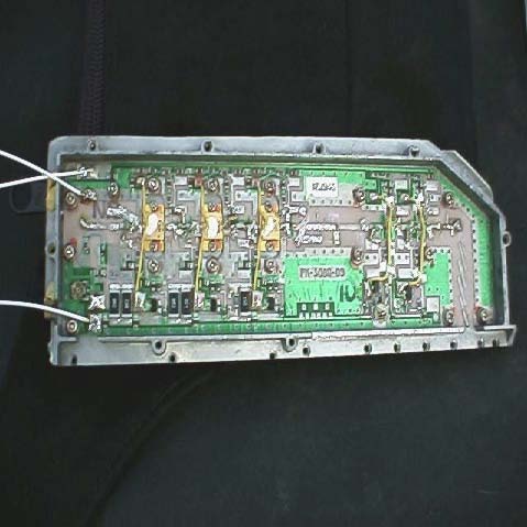
Figure 1
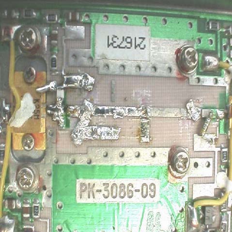
Figure 2
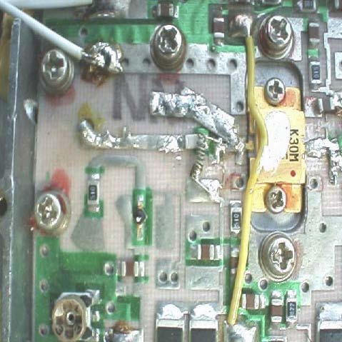
Figure 3
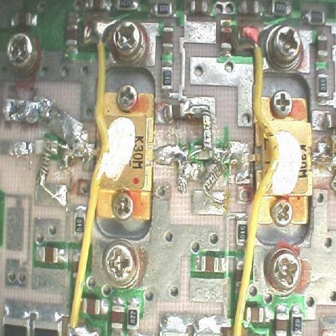
Figure 4
Modifications for 5760 MHz
Modifying the amplifier for 1 watt output at 5760 MHz has proven to require both more time than expected, and more time than I had available to complete prior to submitting this article for the Microwave Update. The same procedure was used for adding the hand-wound bias inductors as in the 3456 MHz modifications above. The first two stages tuned up nicely and showed good gain. The problem was that all of the three power stages refused to produce any gain. My suspicions are that the combination of the internal FET matching and close spacing of the output devices will require different tuning/matching techniques. I have no doubt that the power devices will easily deliver 1 watt output when reasonably well matched. I have had a couple of others express interest in modifying these amplifiers for 5670 MHz as well, so I'm sure that it's just a matter of time. Check the SBMS website listed for updates on amplifier conversion information.
References
- "W1RIL's Qualcomm 10 GHz Mods," Ken Schofield (W1RIL), web document, (4/11/1995).
- "10 GHz Qualcomm Modification Notes," Dale Clement (AF1T), Northeast VHF/UHF Society Proceedings, 1995?
- "Microwave Stripline Retuning Procedures," C. L. Houghton (WB6IGP), web link to this Feb '97 article in 73 Magazine, "Above & Beyond" column, describing talk by Kerry Banke (N6IZW) at ARRL SW Division Convention in San Diego.
- "Modifying the Qualcomm 1W Ku-Band PA for use on 3.4, 5.7, or 10 GHz," Kerry Banke (N6IZW), Proceedings of Microwave Update 2001, Sept. 2001, pp 8-13.
Note: The references above have been republished with the authors' permission on the web pages of the San Bernardino Microwave Society at the following address: www.ham-radio.com/sbms/sd/projindx.htm
(Original Document)