Trunking Digital Signals Decoding
The Interfaces for Decoding Digital Signals
All of the Applications featured by this page require either the 2-Level FSK
interface or the 4-Level FSK interface. You must build this interface, or buy it
from some of sources listed at the bottom of the page. NOTE that these interfaces
DO
NOT provide computer control for your scanner, but rather they interface the
output from your scanner so that the computer and application can decode the digital
signals.
These interfaces connect to the discriminator output on you scanner (and ONLY
the discriminator output) This is usually a connection inside of your scanner
that must be made with a soldering iron.
The Discriminator
The Discriminator output from a scanner is the raw,
unfiltered signal that a scanner produces before it is sent to the audio stage for output
through the speaker -- also called the "baseband audio." This
discriminator source is required for all of the applications featured by this page. Most
scanners must have a simple modification made to them to output the discriminator audio
output to the interfaces outlined on this page.
- See here for a list of discriminator
output locations for many popular scanners - courtesy of Bill Cheek
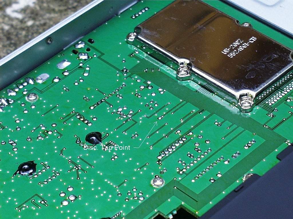
- See this document from Greg Knox regarding
instructions on how to tap the discriminator output on the BC-895 Scanner. See this picture for the location of the discriminator output on
the 895.
- See Bill Cheeks SCANDATA.FAQ listed at the bottom of the page
for detailed instructions on how to tap the discriminator in your scanner.
The 2-Level Interface
The 2-Level Interface (also called the Hamcom
interface) is required for most of the applications that are available for decoding
digital signals today. See the applications page for further information on which
interface is required for each application. There are numerous different version of
this interface, but they all accomplish the same task.
The most popular version of the hamcom interface.
See this picture of how to build
this interface using a Radio Shack experimenters board (thanks to
Mitch Savage KJ5NL mitch1@airmail.net)
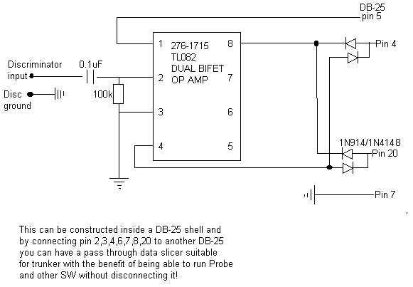
Here is a schematic of the 2-Level interface designed around the TL082 Op-Amp.
This version of the interface works very well! (This is the version that
I use, and it works wonderfully)
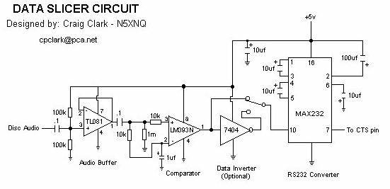
Here is another schematic of the 2-Level interface based around the MAX232 chipset
designed by Craig Clark [cpclark@pca.net].
This interface is very reliable and is reported to work VERY well with Trunker and
Etrunker.
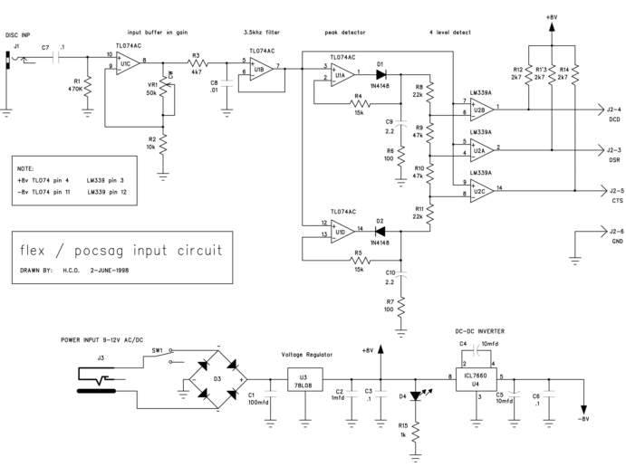
The 4-Level Interface
The 4-Level Interface is a new generation of interfaces
that are required for the faster digital modes. For decoding Flex paging and RD-LAP
MDT modes, this interface will be required. The only production application today
that uses the 4-Level interface today is Pocflex. This interface will however have
further uses when APCO-25 decoding becomes possible.
Here is a schematic of the 2-level and 4-level interface combined into one interface.
Another version of the 4-level interface with power supply can be found below:
Also see this link for PCB Board art work for the 4-level FSK Decoder: http://www.users.interport.net/~carlott/projects.html
Experiences and information from folks who have gotten the
interface working, their testimonials (Tips, Tricks, FAQs, etc)
- Bill Cheek's SCANDATA.FAQ - This is a
great document written by Bill Cheek that will basically answer any questions that you
might have about the 2-Level FSK interface and the discriminator output. It outlines
processes for good circuit design and things to watch out for when building these
interfaces. A MUST READ for anyone beginning a digital signals monitoring project.
(This was updated on 12/19/2000 by numerous contributors..... but many
thanks to the late Bill Cheek for the original submission)
- Bill Cheek's SCANDATA2.FAQ - This is an
update to his previous FAQ, and outlines how to resolve some of the problems that come
with building these interfaces. Also outlines some problem scanners that don't
provide a good discriminator output.
- Bill Cheek's 4FSK.FAQ - This is a
great document written by Bill Cheek that answers any questions you might have about the
4-Level FSK interface and the discriminator output.
- One posted to SCAN-L - Information from a
gentleman who owns a ICOM R-7100
- One by Bill Cheek - This is a posting from
Bill when he was just getting started in Digital Monitoring w/his scanners... ;-)
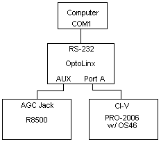
- Here is an experience from someone setting up trunker
with PRO-2006 with an Opto OS-456, an ICOM R8500, and an OptoLinx. Here is a bitmap of the user's setup. If you have an Opto
OS-456 and the OptoLinx.....this article written by David M. Hitchner will really help
you!
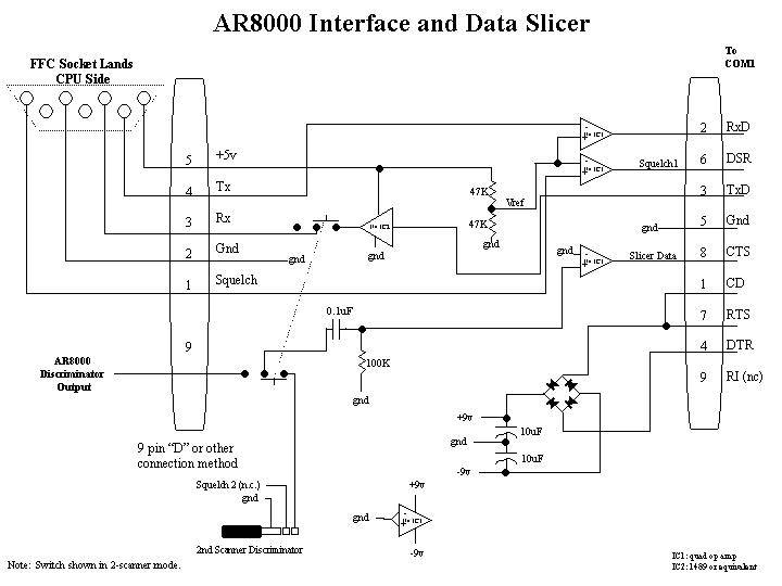
- Getting OptoLinx and an AR8000 working with
trunker/etrunker - Using 1 serial port. Sent by MARK COLBORN [HOTSPOT@worldnet.att.net]
- Getting the Optocom working with trunker. This is a
post from Usenet from a gentleman who was able to get the new Optocom working with
Trunker. He has posted his environment settings and procedures he used to get it
working.
- Data Slicer and AR8000 interface - an
all-in-one schematic for interfacing the AR8000 with a slicer with one
circuit.
- Settings for the AR8200 scanner - getting the AR82000
Scanner to work with trunker is easier than you thought!
- Using the ICOM PCR-1000 with Trunker - this article was
written by Mike Curtis, and explains how he got is PCR-1000 working with trunker.
- Getting the BC-895 to work with Trunker - this article was
written by Mike Curtis, and explains how get got the BC-895 working with trunker and
Etrunker.
- Icom R7000 Interface with new slicer type
- [PDF File] Here is a schematic for an interface used with Trunker and a
Icom R7000. For this example, a PRO-43 scanner is used to obtain
the data channel. The interface obtains power from the Icom, so there
is no issue with weak ports not being able to power the slicer.
The IC Chip used is a MAX203 for minimum parts count, but a MAX232 would
work just as well. The MAX203 can be obtained from Digi-Key. This interface
has also been tested with an Icom R7100. This interface may also work
for other radios that use TTL serial levels if another source of 9-12V is
available, or 5V if the regulator is left out. (Thanks to Gene!)
If you are interested in buying the interface instead of building it, here are links to some
vendors: