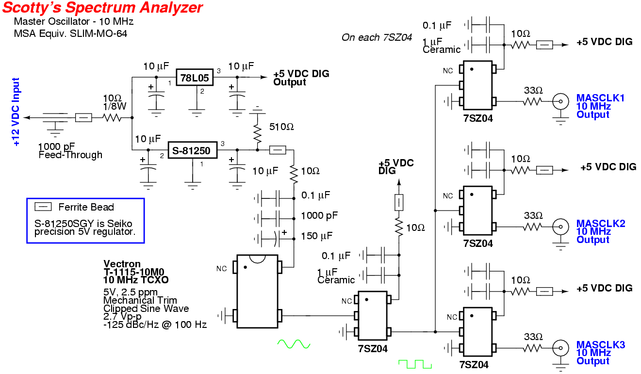
This is my version of the master clock oscillator for Scotty Sprowls' Modularized Spectrum Analyzer (MSA) project. The original MSA oscillator design is SLIM-MO-64.
The main difference here is using a 10 MHz Temperature Compensated Clock Oscillator (TCXO) instead of the recommended 64 MHz clock oscillator. The MSA software has a setting for changing the clock oscillator frequency, and it looks like 10 MHz will work, but this hasn't been tested yet.
The recommended Analog Devices AD9850 DDS has an (undocumented) internal 4x multiplier which can be used to convert the 10 MHz external clock into a 40 MHz internal clock. Since the DDS is programmed to output a 10.7 MHz signal, the minimum internal clock frequency is 21.4 MHz (Nyquist), so the 40 MHz should work out quite well. The overall phase noise will also be slightyly increased by using the multiplier, but should be well within spec. The Analog Devices AD9851 may be a better "drop in" choice. Also, the 1024 MHz second local oscillator for my version of the spectrum analyzer will be done using a Mini-Circuits KSN-1024A+ fixed oscillator and it requires a 10 MHz reference input.
The master oscillator module contains a 10 MHz clock oscillator and three 7SZ04 buffered line output drivers (Digi-Key Part: NC7SZ04M5XCT-ND). Each output is 5 volt CMOS that can drive a 50 ohm line that is terminated with either a high impedance load or 50 ohms. A 33 ohm resistor is shown as a series element in each output.
For a 50 ohm line, with a high impedance load at the end of that line, the mismatched load will create a reflection. The reflected signal will be dissipated in the series 33 ohm resistor plus the internal resistance of the 7SZ04 driver (approximately 17 ohms). For a 50 ohm line, with a 50 ohm load at the end of that line, the 50 ohm load will receive a 2.5 volt peak-to-peak square wave. If this is not sufficient, the 33 ohm series resistor can be replaced with a low-impedance coupling capacitor (0.01 µF).
The clock oscillator used here is a Vectron T-1115-10M0 miniature 10 MHz TXCO. These are available for $6 (for two) on eBay from the seller "rfextra." They appear to have a custom part number, but the datasheet for the "OSC Series" of oscillators from Vectron covers this model.
These Vectron oscillators have decent specifications for such a low cost and small package. They have a +/- 2.5 ppm frequency stability with a +/- 3 ppm mechanical trim adjust on top. Phase noise at 100 Hz is -125 dBc/Hz and at 1,000 Hz is -145 dBc/Hz. The mechanical trim adjustment will require a special trim tool (Vectron Part: KMDR050) - or you just need to do a little bit of hacking in order to tweak the final output frequency. The stock, untrimmed output frequency of the oscillator used here was 9,999,987 Hz after about 15 minutes of warm-up time.
The 7SZ04 high-speed inverters are required to reduce clock jitter and hence phase noise. Also, using individual inverter/buffers allows you to decouple each of their Vcc lines from each other, further reducing the potential for EMI.
Using a square wave clock for a spectrum analyzer has the potential to generate alot of strong harmonics which may be seen as spurious images on the analyzer's display screen. For this reason semi-rigid hardline coax, such as RG-402, RG-405, UT-141, etc., should be used throughout the spectrum analyzer project.
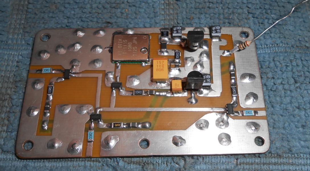
Overview of the 10 MHz TCXO master oscillator circuit board.
The +5 VDC power supply for the oscillator should be from a very stable and fairly low-noise regulator, like a Sieko S-81250SG or TL431 reference, but a regular 78L05 will do.
Most voltage regulators can have their output voltage noise reduced by increasing their output current with an extra load resistor. A 510 ohm resistor will provide a steady 10 mA current draw at 5 volts.
Ideally, the Vectron T-1115-10M0 oscillator should have its own +5 VDC low-noise voltage regulator to help further isolate it from the digital switching logic noise.
The pictures don't match the schematic due to circuit tweaking. The schematic is correct.
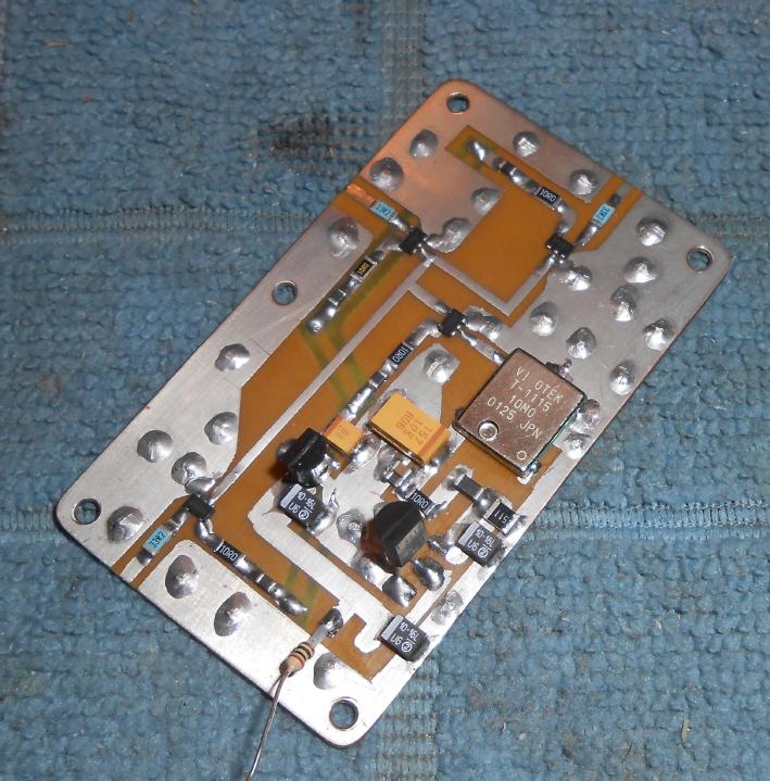
Alternate view
The +5 VDC voltage regualtors are the two TO-92 devices on the bottom.
The Vectron oscillator requires a special trim tool - which I didn't have.
I ended up using a fine-tipped metal scrib to "twist" the tuning control a bit to raise the frequency a few Hertz.
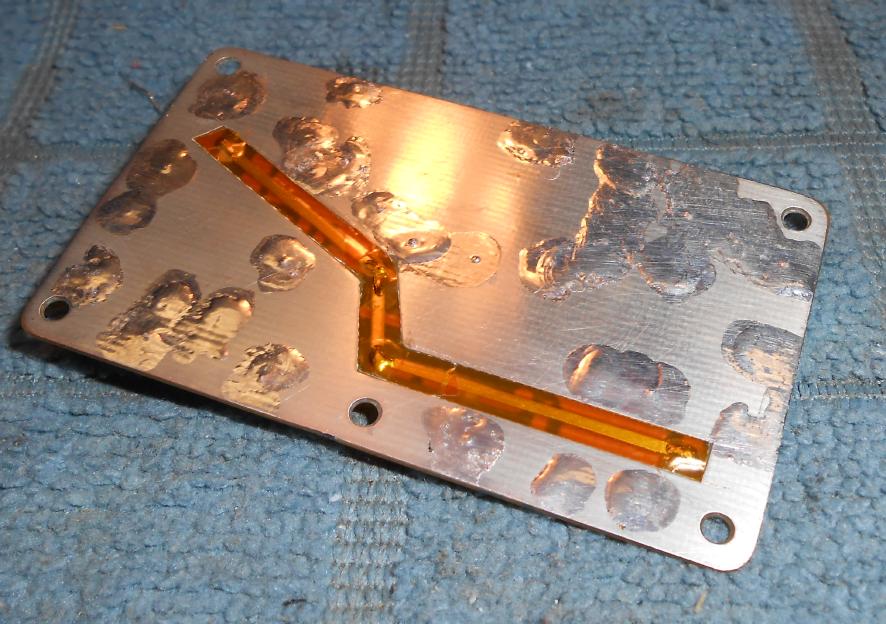
Overview of the bottom of the printed circuit board.
The trace is for the +5 VDC power for the 7SZ04s.
It's covered in Kapton tape to prevent it from shorting out when mounted in the case.
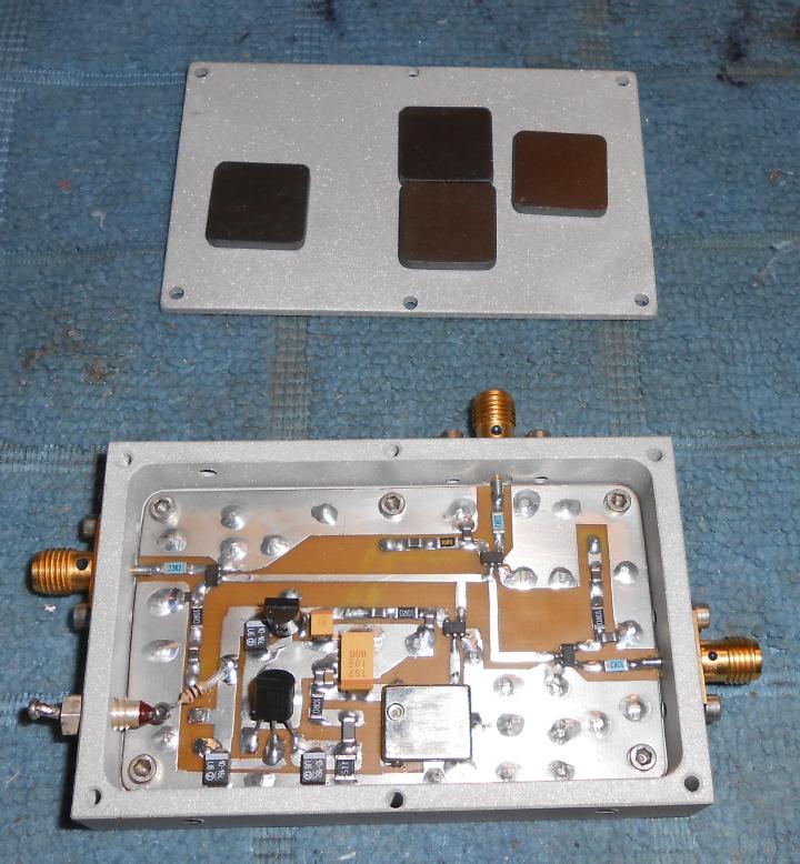
Mounting the 10 MHz master oscillator circuit in an old cellular phone receive pre-amplifier case.
Three SMA jacks are used for the clock outputs.
A 1000 pF feed-through capacitor is for the +12 VDC power input.
The lid of the case has a few stick-on ferrite EMI absorption plates (Digi-Key Part: 240-2264-ND). These are optional, but the idea is to help reduce any radiated interference from creating spurious images on the spectrum analyzer display.
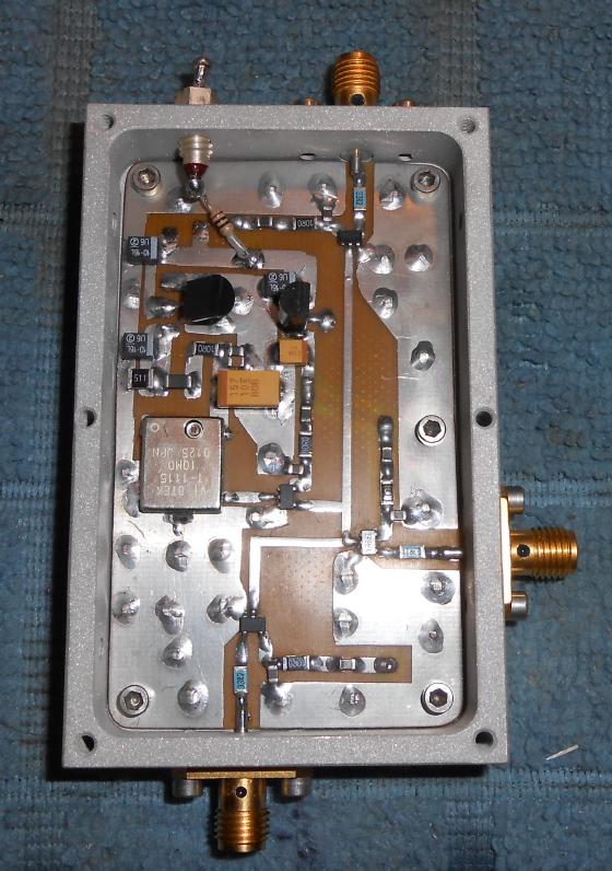
Completed 10 MHz master oscillator circuit overview.
The MASCLK1, MASCLK2, and MASCLK3 connections should be via 100% shielded RG-405 or UT-141 semi-rigid coax to reduce interference.
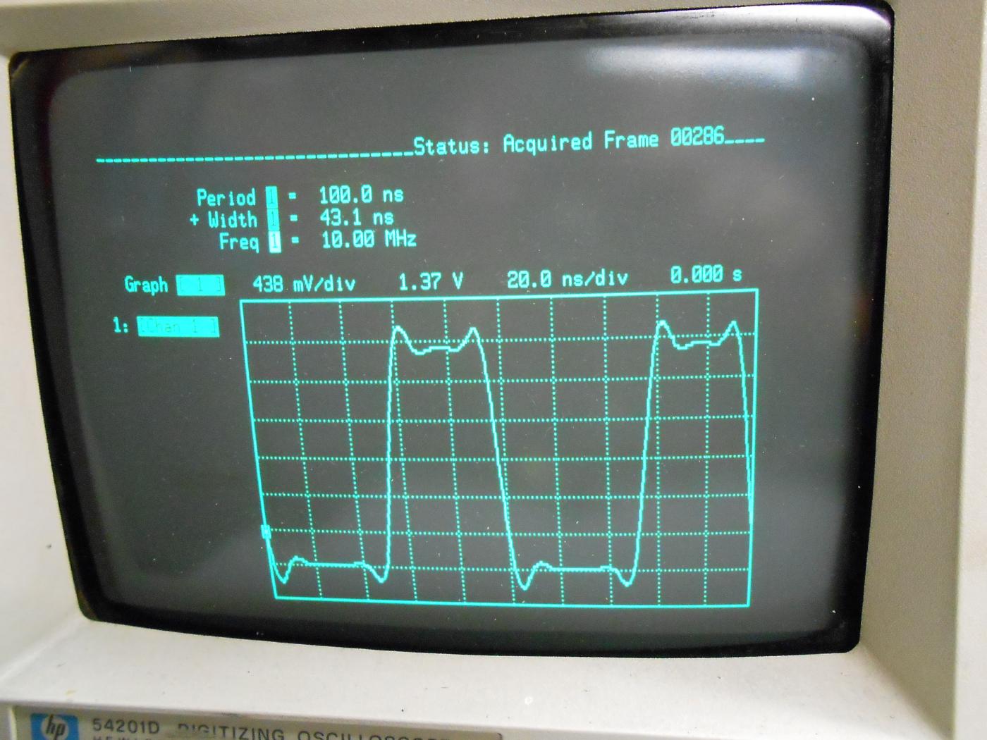
HP 54201D 100 MHz oscilloscope view of the output waveform.
No major circuit problems or oscillations were found.
The waveform has a 100 nanosecond period with a 43.1 nanosecond pulse width for close to 50% duty cycle.
Most low-cost clock oscillators of this type provide a 60/40 percent duty cycle.
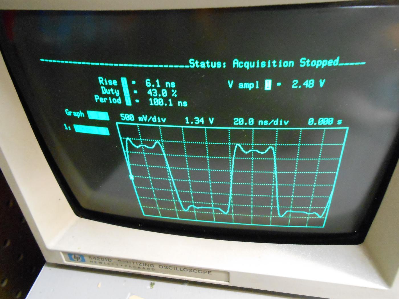
Oscilloscope screen view showing:
- 6.1 nanosecond rise time
- 43% duty cycle
- 100.1 nanosecond period
- 2.48 voltage amplitude
The output voltage is "halfed" as the scope was set for a 50 ohm termination.