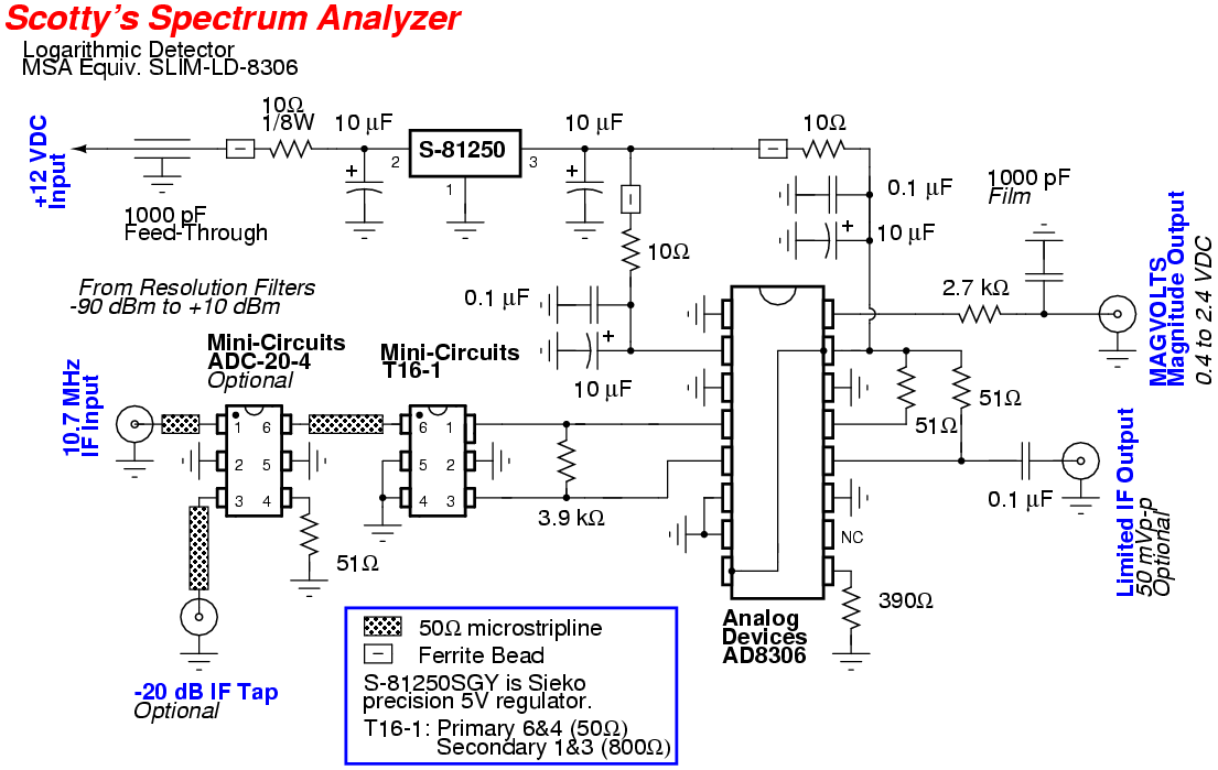
This is my version of the logarithmic detector for Scotty Sprowls' Modularized Spectrum Analyzer (MSA) project. The original logarithmic detector design is SLIM-LD-8306.
The only major change was adding a Mini-Circuits ADC-20-4 20 dB directional coupler to tap the incoming (filtered) 10.7 MHz IF signal. This signal will be routed to a panel-mounted RF connector on the spectrum analyzer's case for further processing. Using a 10.7 MHz FM/AM/video/etc. demodulator will allow the spectrum analyzer to be turned into a high-performance communications receiver.
The Analog Devices AD8306 High-Precision Limiting-Logarithmic Amplifier (Digi-Key Part: AD8306ARZ-ND) used in this module has two functions. Its main purpose is as a RF detector to convert the incoming RF signal (at 10.7 MHz) to an equivalent DC voltage representation of the power level (also called the Received Signal Strength Indicator - RSSI), and it can also act as a high-gain, RF-limited amplifier for use with the optional Vector Network Analyzer (VNA).
The RSSI dynamic range is approximately -90 dBm to +10 dBm, with a corresponding DC output voltage of +0.4 volts to +2.4 volts on the module's MAGVOLTS output.
The logarithmic detector module has an input impedance of 50 ohms and an operating bandwidth of approximately 3 MHz to 120 MHz. The RF bandwidth of the module is mainly determined by the pass bandwidth of the input Mini-Circuits T16-1 (50 to 800 ohm) impedance matching transformer, which is 120 MHz maximum in this case. The AD8306 itself has a much wider operating bandwidth, to well over 400 MHz.
Using a wideband transformer instead of a narrowband matching network allows the logarithmic detector module to be used as a "drop-in" replacement module if you wish to use an alternate final IF frequency or design.
The input Mini-Circuits transformer can be replaced with a similar 1-to-16 ratio impedance matching transformer, such as the Coilcraft WBC16-1TLB, which is available as a free sample. It could also be omitted entirely and replaced with a proper inductor/capacitor impedance matching network, but this is only suitable for narrow frequency bandwidth applications. Refer to the AD8306's datasheet for the proper component values to use and their configuration.
The AD8306's limited IF output is biased by the 390 ohm resistor for a minimal (1 mA) output. This will help prevent excessive feedback within the module which could induce self-oscillation and create spurious images. The AD8306's limited IF output is a 50 mV peak-to-peak square wave equivalent of the incoming IF signal The AD8306's limiter input dynamic range is from approximately -77 dBm to +10 dBm. This output can drive a high-impedance or 50 ohm load.
The input impedance for the logarithmic detector module is designed for 50 ohms, while the input impedance to the Analog Devices AD8306 is around 1000 ohms. This is why the Mini-Circuits T16-1 transformer is included on the input. A parallel 3.9 kohm resistor was added to match the approximate 1000 ohm input impedance of the AD8306 to the 800 ohm output impedance of the Mini-Circuits T16-1 transformer for maximum power transfer.
The Mini-Circuits T16-1 is a 1:4 turns ratio transformer, which means the voltage transformation ratio from the primary to secondary is 1-to-4 (1 volt to 4 volts, for example). The impedance transformation ratio is equal to the number of turns squared, or 1-to-16 (50 ohms to 800 ohms, for example). The power transformation should be 1-to-1, but there is some slight loss within the Mini-Circuits T16-1.
Since the AD8306 has a high input impedance (1000 ohms), Analog Devices uses voltage measurements (dBV) in their datasheet and not power (dBm) measurements. I am using power measurements (dBm) in the previous paragraphs, because I am specifying the inputs and outputs of the module itself, not the actual AD8306. Once we move from the T16-1 transformer's primary to the secondary, we are no longer in a 50 ohm system. It is also more accurate to use voltage measurements at this point.
As a reference point, let us assume the input voltage to the module (primary of transformer) is 1 volt (RMS). This is 0 dBV. The output of the transformer (1:4) is 4 volts (RMS). This is +12.04 dBV. The transformer looks like it has a gain of 12.04 dB. For voltage only, this is true. But for total power, there is no gain.
Analog Devices specifies the dynamic range of the AD8306 to be from -91 dBV to +9 dBV. Since this is the secondary of the transformer, the dynamic range on the primary side is -103 dBV to -3 dBV. This equates to a 50 ohm power input of -90 dBm to +10 dBm.
The limiter amplifier of the AD8306 begins limiting at approximately -78 dBV and remains stable up to +9 dBV. This equates to an input voltage on the primary side of the transformer of -90 dBV to -3 dBV. As a 50 ohm input power to the module, this is -77 dBm to +10 dBm.
If the limiter output of this module is never going to be used, it is advisable to omit the 51 ohm pull-up resistors on pin 12 & 13, and the 390 ohm current setting resistor on pin 9. This will lower overall power consumption and eliminate any possibility of limiter feedback oscillations.
It should be noted that this module is extremely sensitive to outside noise influence and temperature. It is important that this module be totally shielded without any of its connections exposed to the outside, and it should be mounted in the coolest spot possible.
Below is the AD8306 logarithmic detector module's RF input power (10.7 MHz) to DC voltage (MAGVOLTS) mapping. With an open on the IF input, the output was 0.457 volts and with a 50 ohm load the output was 0.372 volts. That will be the baseline for minimum signal detection which is around -100 dBm. The logarithmic output voltage slope is 20 mV/dB.
RF Input (dBm)           MAGVOLTS Output (Volts)
-100.0                   0.374
-90.0                    0.397
-80.0                    0.524
-70.0                    0.722
-60.0                    0.924
-50.0                    1.126
-40.0                    1.331
-30.0                    1.534
-20.0                    1.737
-10.0                    1.947
  0.0                    2.155
+10.0                    2.367
That mapping is for the logarithmic detector module only. The finished spectrum analyzer will require a proper calibration which will result in slightly different output voltages because of the losses in the mixers/filters and gain from the 10.7 MHz IF amplifier.
The logarithmic detector module must be preceded by a narrowband resolution filter stage to limit the input noise and to help further increase the maximum signal detection sensitivity.
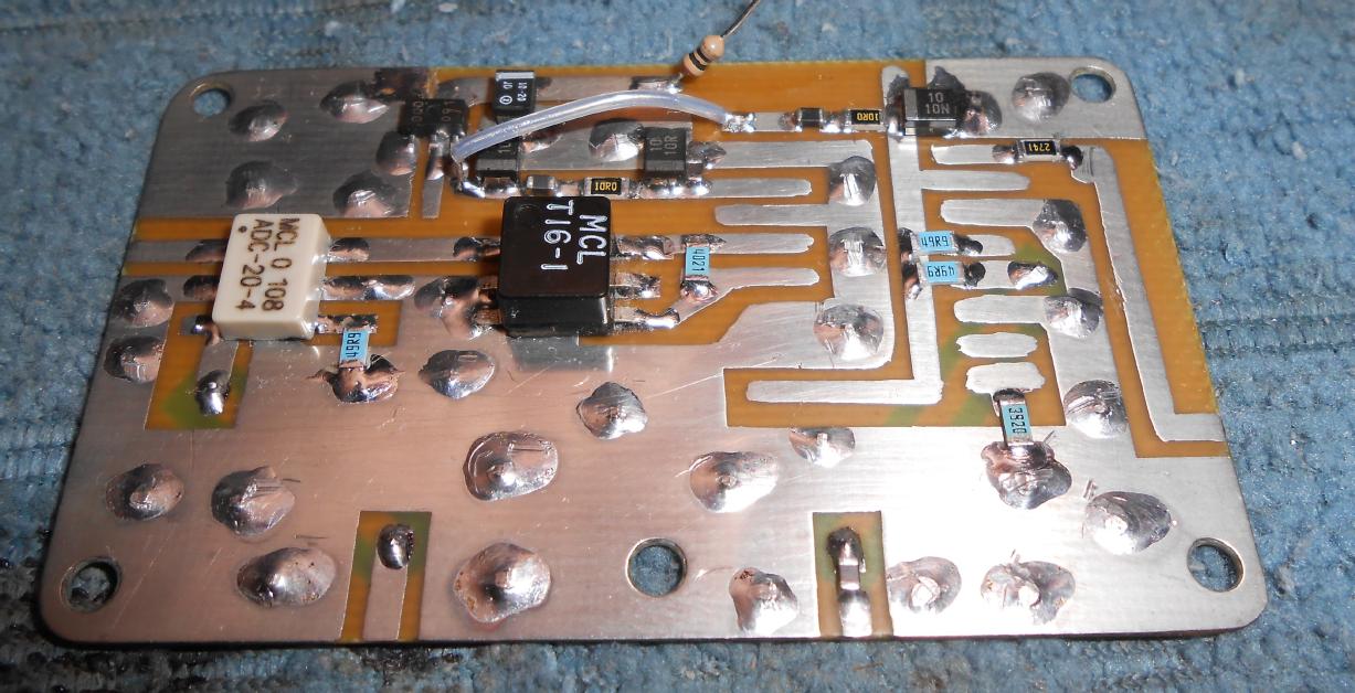
Overview of the logarithmic detector circuit board before the installation of the AD8306.
The Analog Devices AD8306 will be mounted on an optional 16-pin SOP-to-DIP carrier board for easier soldering.
The 10.7 MHz IF input from the resolution filter is on the left side.
The white box device is the Mini-Circuits ADC-20-4 directional coupler providing the -20 dB tap.
The black box device is the Mini-Circuits T16-1 impedance matching (50-to-800 ohm) transformer.
Note that the index mark on the Mini-Circuits T16-1 is pin 6!
The +5 VDC power supply for the logarithmic detector circuit should be from a very stable and fairly low-noise regulator, like a Sieko S-81250SG, but a regular 78L05 will do.
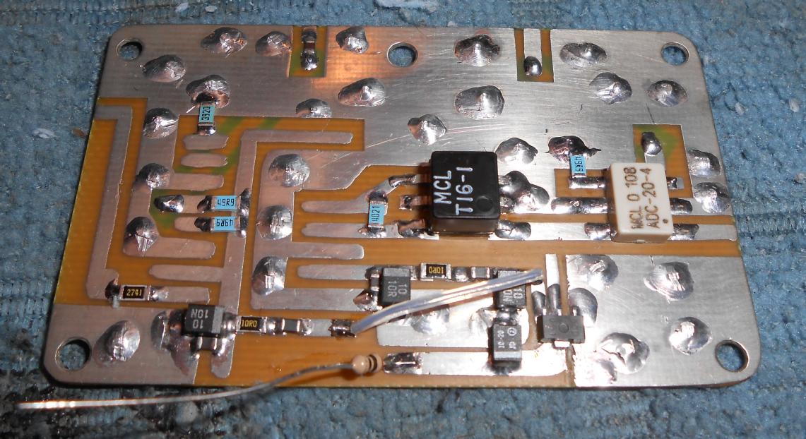
Alternate view.
The SOT-89 device is a Sieko S-81250SG precision 5 volt regulator.

Overview of the bottom of the printed circuit board.
These are the traces for the limited IF output and the directional coupler output which are connected back to the case's SMA connectors.
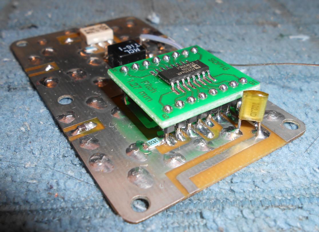
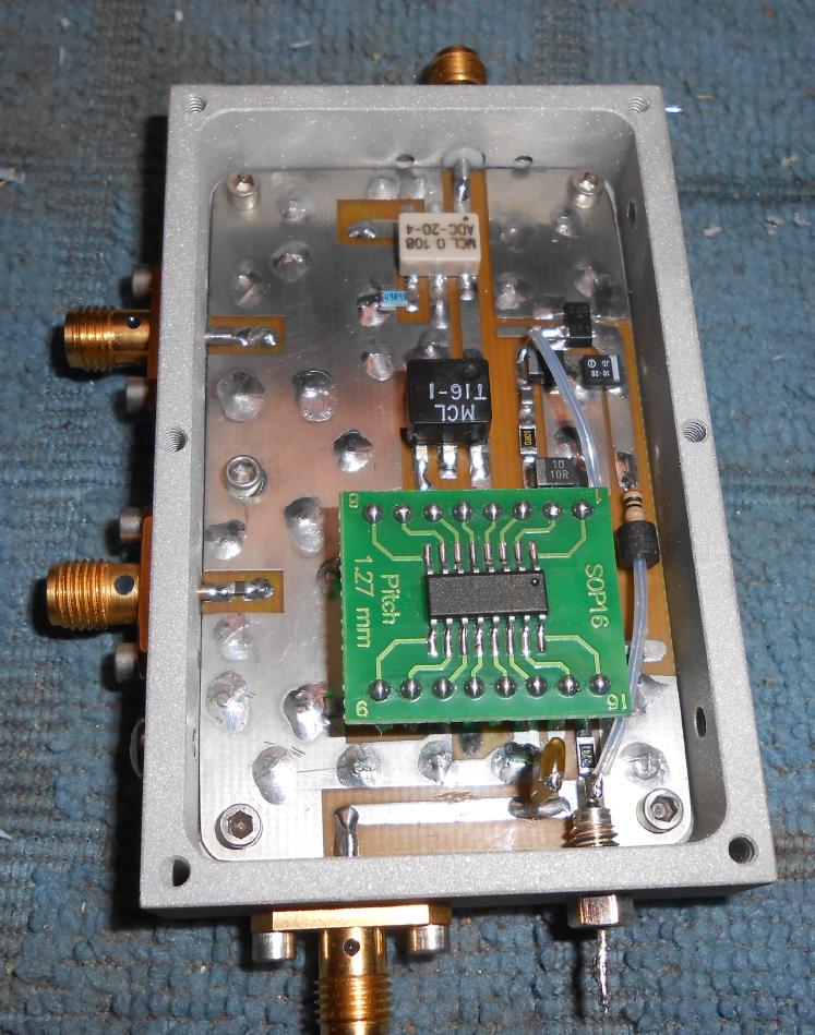
Installing the Analog Devices AD8306 with the SOP-to-DIP carrier board.
Technically, this device should be surface-mounted without the carrier board, but at 10.7 MHz we can get away with a little bit of extra inductance.
Note the 1000 pF low-leakage polystyrene filter capacitor on the MAGVOLTS output. This video filter capacitor should be of high quality and non-microphonic.
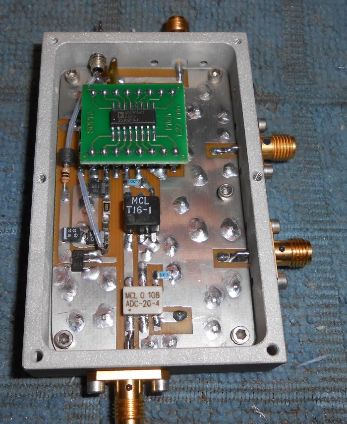
Completed overview of the logarithmic detector.
It's mounted inside an old 800 MHz cellular phone receive pre-amplifier case.
Four SMA jacks are used for the 10.7 MHz IF Input (bottom), -20 dB IF Tap (right-side, bottom), Limited IF Output (right-side, top) and the MAGVOLTS (top) output.
Alternate view.
A 1000 pF feed-through capacitor is used for the +12 VDC power input.
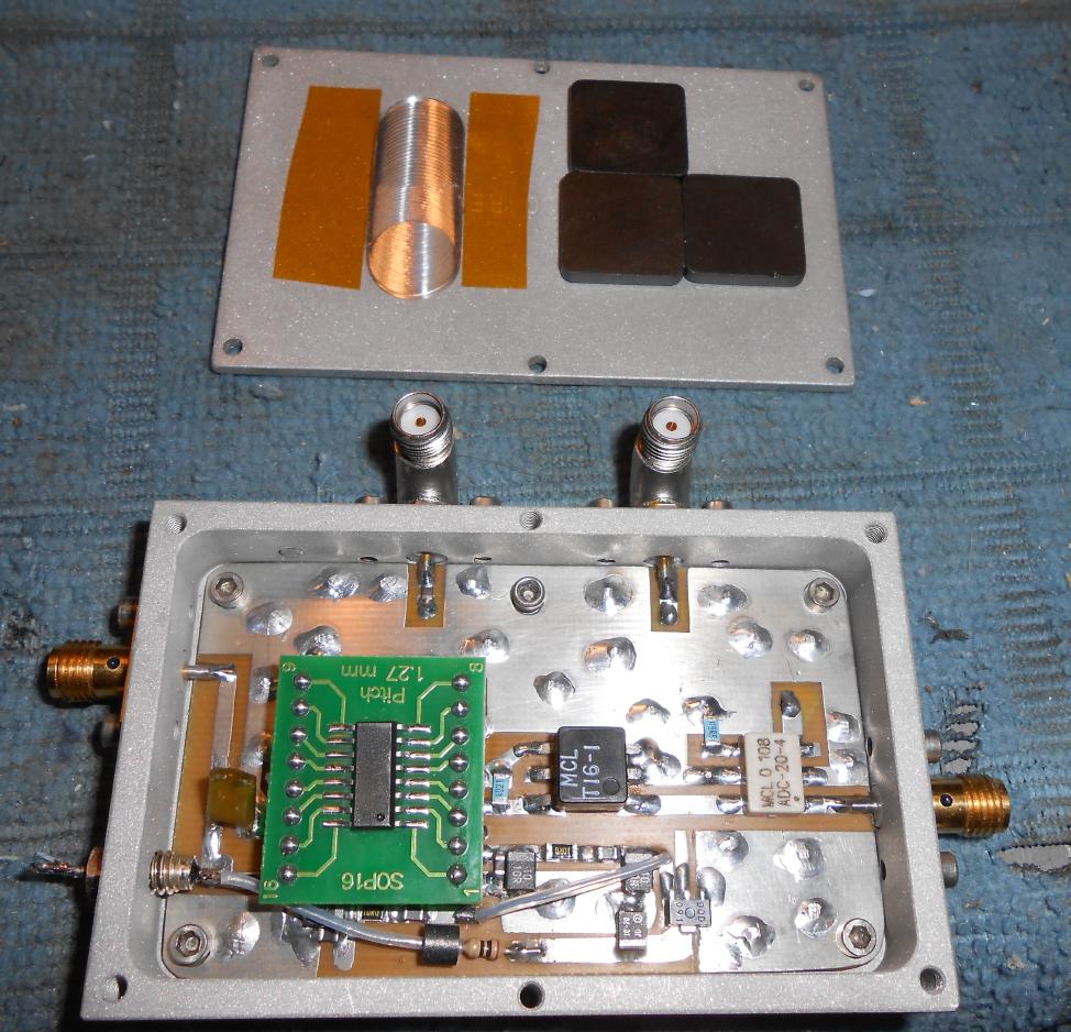
The AD8306 mounted on the SOP-to-DIP carrier board was just a little too high to fit inside the case, so I had to mill out a little bit of the top cover plate so it would sit flat.
The lid of the case has a few stick-on ferrite EMI absorption plates (Digi-Key Part: 240-2264-ND). These are optional, but the idea is to help reduce any radiated interference from the limited IF output from creating spurious images on the spectrum analyzer display.
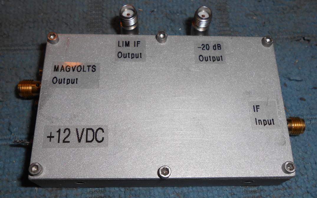
Finished case overview.
I had to add right-angle SMA jacks as the rack-mount case I'll be mounting these modules in is just a little too small.
The MAGVOLTS output of this module will then be connected to the 16-bit Analog-to-Digital Converter stage before being processed by the computer.
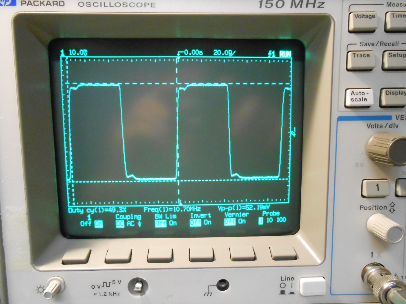
Oscilloscope view of the limited IF output signal.
The limiting action kicks in at around a -77 dBm IF input and remains constant up to +10 dBm.
The output signal is a square wave representation of the input IF signal at around 50 millivolts peak-to-peak.
The limited IF output signal should be very well shielded to prevent feedback oscillation or spurious images from being created.