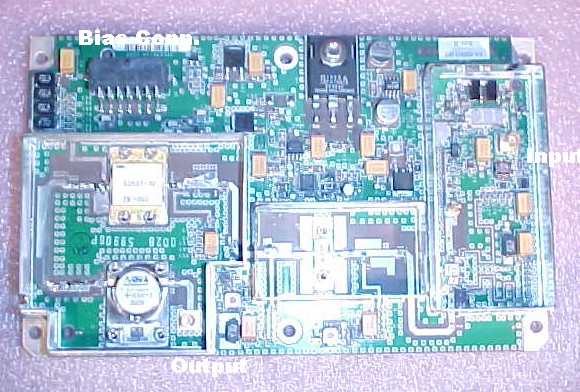
This is for one very linear Class A RF amplifier which I have removed from a new Spectrian high-power amp where it was used for driver for the main PA boards. This amplifier has been selected, setup and tested for an output power of 30W @ 2.304 GHz with a linear gain of 35 dB.
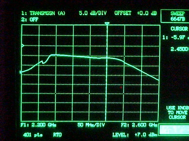
Input power for 30W output is typically 10 mW or less! I have attached a plot of power vs frequency. The upper-left reference tick marks the 100W (+50dBm) point with 5 dBm per vertical division. Frequency is 50 MHz per division. Input drive for this example was +7.0 dBm.
Power requirement is 13-14V @ 10A and +18 to +28V bias at 50 mA. This bias is used for the gate voltage circuit on the power control FET. I do supply a miniature regulated DC-DC converter with this auction which takes 12-15V input with an output of 12V @ 85 mA for generating this bias voltage by putting the isolated output in series with this 12V input voltage. Please note! You must put a 47 ohm resistor in series with the output of this converter then connect the other end to pin 14. This protects the DC converter from inrush current into the 4.7 µF tantalum on the amplifier board.
There is a logic level enable pin which requires grounding to enable power to this amplifier and can be used for a PTT/KEY control. The connector also has a direct temperature output pin with the function 10.0 mV/°ree;F which measures the board temperature close to the 30W RF output GaAs FET (NEC S2527-30).
Note that the output of this amplifier is protected by an internal 125W isolator!
Here are the pin functions for the DC bias connector: Pins 1, 2, 3, 4 are all +12.6 to 13 VDC at 7.5 or so amps.
Pins 5, 6, 7, 8, 10 are all ground.
Pins 12, 13 are No Connection.
Pin 11 is logic-level low enable, normally floats high. This turns on the +12V to the internal transistors.
Pin 14 is +26V bias supply input at 50 mA.
Pin 9 indicates temperature = 10 mV/°ree;F.
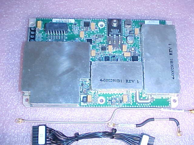
This board comes mounted on a 1/4-inch thick aluminum heat spreader which has 6 mounting holes for mounting to a heat-sink.
I am also supplying the two MCX 0.085-inch hard-line sections as well as the mating bias connector as shown. You will find it very easy to remove one of the MCX connectors from one end of these and replace it with a SMA 0.085 hard-line connector.
Board dimensions are 6.5 x 4 inches.