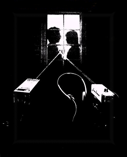

Use a light beam to listen in to anything, anywhere, any time...
Breaking and entering to plant a listening device is one way to "bug" a
room.
This data is presented for information purposes only...
Unfortunately, it can earn you a long jail term.
A safer way to bug a room is to use a laser beam
to eavesdrop on a window
from across the street...
It is also highly illegal...
Consult legal counsel before attempting to construct this device...
The sound waves generated by nearby conversation will cause the glass in a window to vibrate very slightly. If a laser beam is bounced off the window, its reflection will be modulated by the vibrations.
All that's needed to hear what is being said is a demodulating device that extracts the audio from the reflected laser beam That technique is used by sophisticated "surveillance experts," but you can easily duplicate that feat by using a hobbyist's laser and the inexpensive Laser Listener demodulator shown in Fig. 1.
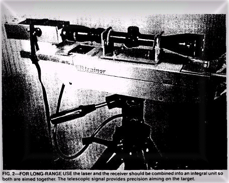
If you need something a little more sophisticated it can be made part of the riflescope aimed laser-bug system that is shown in Fig. 2.
WARNING
Extra precautions must be taken because of a laser beam's intense concentrated energy. Among other factors, the hazards presented depend on the power density, the frequency of the beam, and the time of exposure. Guidelines have established the classification of lasers.
A brief description of the classification is as follows:
Class I: Low-power beam. Not known to produce any biological injuries
to the eye or skin.
Class II: Reserved for visible-light lasers only. They are limited to less
than 1 milliwatt output. Eye damage will result if stared into for longer than 1
second.
The normal blink response of the human eye will provide protection.
Eye damage will occur if the beam is viewed directly by optical instruments.
Direct (specular) reflection, as from a mirror, should be considered to be the
direct beam.
Diffuse reflection of the light may be viewed.
Class III: Instantaneous eye damage will occur if exposed to the direct beam.
Class IV: Both direct exposure or direct and diffuse reflections will produce eye damage. Exposure of the skin to the beam is hazardous. The beam is considered to be a fire hazard.
Early light-wave communications
Communication using a modulated beam of light isn't a new idea. In the 1880's, Alexander Graham Bell experimented with something he called a photophone; a device that modulated a beam of sunlight. It had a Mouthpiece that concentrated sound energy on a reflecting di-aphragm, which, in turn, modulated a beam of sunlight that was aimed at the diaphragm. When a remote receiver consisting of a photovoltaic cell and a sensitive earphone was positioned in the beam, the voice could be heard clearly from the receiver.
The aiming problems presented by the movement of the sun, and the interruptions due to clouds and night, probably prevented the commercial exploitation of the device. But by using coherent light-such as that produced by a continuous-wave laser-the principles used by Bell's device may again be applied in a meaningful way. After all, terrestrial lasers aren't influenced in any way by sunlight or clouds. And perhaps more important, unlike acoustic sound-detection devices, lasers aren't usually subject to interference originating between the sound source and the receiver. For example, remote sound-pickup devices in the form of directional microphones have been available for many years.
Unfortunately, any sound generated between the listener and the sound source usually renders the device useless because the interference is heard at the receiver, and it can be even louder than the source. On the other hand, lasers are not sensitive to sound of any kind between the source and the receiver. However, lasers may be subject to other kinds of interference: For example, AC-powered incandescent lights can produce a hum; gas discharge devices such as fluorescent, mercury, sodium vapor, and neon lights might produce a buzz; and direct sunlight might swamp the laser detector device.
Also, where unusually long distances are involved, air currents can add flicker to the laser beam, which on windy days can result in a noise that is similar to that of blowing into a microphone. (But even though sensitive to some kinds of electrically-generated noise, laser- listening devices have an advantage: They can seemingly hear through walls or closed windows, and even selectively monitor only one window of a building from several hundred feet away.) Commercially available laser sound pickups use a laser device having an output in the infrared region.
Because infrared is below the visible portion of the light spectrum, it cannot be seen by humans. However, some commercial devices have a power output rating as high as 35 milliwatts. At such a power level there is clear potential for eye damage if someone in the target area unknowingly stares into the beam, or if the laser is operated carelessy by the user.
Laser basics
Although the details underlying the generation of laser light are beyond the scope of this text, an understanding of some of the characteristics of a laser beam as compared to ordinary light will be helpful in assembling a laser-listener system. Light is considered to be comprised of packages of energy particles called photons.
However, light is also electromagnetic radiation and behaves like radio waves, although at a much higher frequency. The perceived color of visible light is determined by the radiation's wavelength, which is usually given in micrometers. The shorter wavelengths are perceived as violet, the longer wavelengths as red. The spectrum below the visible portion is called infrared; the spectrum above is called ultraviolet. The light emitted by a conventional incandescent or fluorescent source contains a wide range of frequencies, and the photons are emitted randomly and spontaneously in all directions.
On the other hand, in a laser light source the photons are released in one direction, at one frequency, making the laser light highly directional and pure in color. (An analogy would be to liken ordinary light to white noise, while the laser is likened to a sinewave-a single pure tone.) Since all of the light emitted by a laser is coherent (has the same frequency), constructive or destructive interference occurs when two beams of laser light meet at the same place and time (Fig. 3).
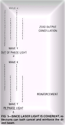
As shown in Fig. 3-a, the beams cancel each other when out of phase (destructive interference). As shown in Fig. 3-b, the beams are additive when in phase (constructive interference).It is the interference between the beams that enables the movement of any reflectingsurface to be sensed by a device called a interferometer. An interferometer is a beamsplitter usually a piece of partially-mirrored glass that deflects only a small part of a beam aimed through the glass. As shown in Fig. 4,
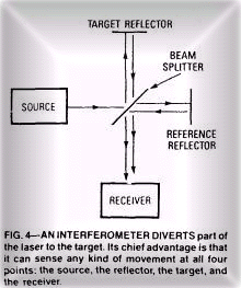
it can be used to reflect both the source and the reflected laser beams so that their phasing or amplitude can becompared by a receiver. The major problems with using interferometry for eavesdropping is that only a part of the laser's energy is directed at the target, limiting the working range, and the interferometer is sensitive to the diffusion of the sounds target's reflections caused by tremors in the mountings of the interferometer, the laser, and the reflective target. For super-snooping, a direct reflection from the target is preferred because the collimated nature (parallelism) of laser light also allows modulation of the beam to occur just as Bell`s photo-phone modulated the sunlight.
The prototype's laser Regardless how we choose to eavesdrop, we must start out with a laser, so we' ll cover the prototype laser bug's unit first. It's a (CENSURED) unit having an output power of 0.9 milliwatts. It has a beam divergence of 1.64 milliradians, which produces a spot of light 11/2 inches in diameter at 200 feet. Although 0.9 milliwats doesn't appear to be much power, it can cause extreme eye damage if allowed to shine or be reflected directly into the eye, or if viewed directly through any optical device such as a telescope, binocular, etc. The beam may be safely viewed only if projected onto a non-reflective surface such as a white sheet of paper. It' you want to keep costs at rock-bottom, or just want the excitement of a complete home-brew project, another alternative is to assemble the helium-neon laser shown in the June 1986 issue of Radio-Electronics. Also. if you want to build a laser from your own design, helium-neon tubes are often available from "surplus" distributors.
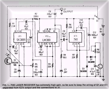
The receiver
The Laser Listener's receiver is relatively easy to build and adjust. It is designed to drive a 4-20-ohm headphone or speaker. Which permits just about any high-fidelity or Walkman-type headphone to be used for monitoring. The circuit shown in Fig1, uses a photo transistor (Q1) for a sensor, and has a meter (M1) that indicates the relative signal strength of the reflected laser beam. Because the Meter responds only to the amplitude modulation of the reflected laser beam, it is unaffected by ambient light and the relative intensity of the laser beam. An adjustable polarizing light filter can be installed in front of Q1 to avoid swamping of the phototransistor by very high ambient light. Phototransistor Q1 is an inexpensive type usually called an IR detector, which Means that it is specifically sensitive to infrared light. Tests comparing the unit specified in the partlist with other less readily-available and more-expensive devices show no measurable difference in performance in the prototype receiver. No base connection is used for Q1 because the reflected laser light controls the collector current. The audio signal developed across collector load-resistor R1 is coupled by C2 to voltage-controlled attenuator IC1, which has a greater than 30-dB gain variation; It serves as both a preamplifier and as an electronic volume control.
Resistor R2 and capacitor C1 decouple (filter) the power supply voltage to Q1 and IC1. Be sure to take extreme care, not to eliminate or accidentally bypass the filter because that will cause unstable operation. The gain of Q1 and IC1 is too great to permit non-decoupled operation from the power supply. The output from IC1 is fed through C4 to amplifier IC2. Resistor R4. and capacitors C5 and C7, tailor IC2's frequency response and ensure stable operation with varying drive levels and output loads. The output of IC2 is split into two paths: One goes to output-jack J1 via C6; the other feeds voltage-follower IC3, which drives the meter circuit consisting of D1, D2, C11, R8, and M1. The time constant created by the values of R8, C11 and Mi's DC resistance was selected to provide a comfortable damping of the meter pointer's gyrations. The value of C11 may be varied to change the pointer's response. Increasing the value of' C11 provides a smoother response; decreasing C11's value will cause the pointer to more closely track the variations in the laser beam's modulation.
Construction
The prototype receiver was assembled on a modified Radio Shack type 276-170 pre-drilled PC board, which has strips of copper foil on the underside that connect the component mounting holes. (A board with a parts-placement template in place, as shown in Fig. 5, is available from the source given in the partlist.) Nothing about the layout is critical as long as you follow the usual precaution of keeping the input and output connections reasonably separated. Check your parts layout against the foil strips on the underside of the board. If it appears that any will be too long, cut them to size before mounting any components. Cut each foil strip exactly as long as needed so that a foil carrying the input signal doesn't end up running adjacent to an output connection. For best results when making connection to the foils, use a small pencil-tipped soldering iron and .040 diameter rosincore solder. If your layout requires jumpers between component mounting holes, use #22 solid, bare wire. Insulated junipers are #22 solid, insulated wire. Connection between the copper foils should be #18 insulated wire because it's a precise push-fit for the holes in the specified prototyping board. The enclosure is a 61/2 x 21/8x 15/8 inch aluminum cabinet. Phototransistor Q1 protrudes from one end of' that enclosure and is mounted with a dab of household cement. Position Q1 correctly before gluing it in place and be very careful to not get glue on the surface of the lens. Do not use cyanoacrylate-based instant glue because it might cloud the transistor's plastic lens. Output-jack J1, gain-control potentiometer R5, and the meter are mounted on the side of the cabinet , so as to encourage the user to face at a right-angle to the source of the laserlight, thereby lessening the change of looking directly into the reflected beam. The board is mounted in the enclosure with four 3/4 inch 6-32 machine screws. Use 1/8 inch insulated spacers between the board and the enclosure to insure adequate clearance between the enclosure and the board's foil side. A ground lug located at one mounting screw is soldered to the circuit-board's ground foil to provide the ground connection between the board and the cabinet. The connections between the board and the panel-mounted components can be #18-22 stranded, insulated wire.
Optical attenuator
The optical attenuator assembly, for which construction details are shown in Figs. 6 and 7, mounts over phototransistor Q1.
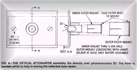
Figure 6 shows how it's installed over Q1: Fig. 7 shows the individual details for each component in the assembly.
The front of the assembly is painted flat white so that the reflected laser beam can be easily seen The attenuator is built in such a way that the phototransistor can see the laser beam directly, or through a combination of one or two polarizing filters.
When both filters are in place, rotation of the large-diameter filter-mount will cause a gradual decrease in light transmission (to almost total blockage within 90 degrees of rotation), which allows the receiver to be used over a wide range of light intensities without swamping the photo detector.
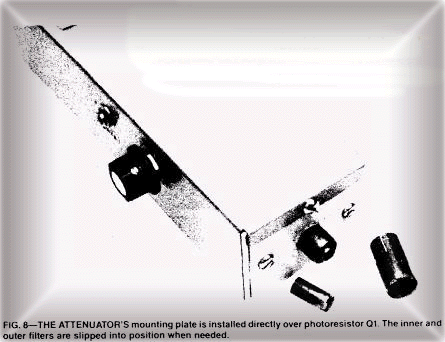
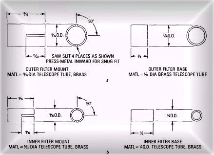
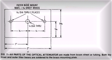
Figure 8 shows the installed assembly and the two filters. The attenuator has an inner filter and an outer filter made from brass telescopic tubing. Each filter consists of two sections: a filter base that is soldered to small mounting plate made from brass sheet (the painted target), and a filter mount that slips over the base. Polaroid fillers cut from neutral-tint polarized sunglasses are cemented to one end of each filter mount to complete the attenuator. When complete, the entire optical attenuator's mounting plate is secured on the enclosure over phototransistor Q1.
Parts list
All resistors are 1/4 watt, 5% unless otherwise noted.
R1-2200 ohms
R2-220 ohms
R3-33000 ohms
R4-10 ohms
R5-10,000 ohms,
miniature potentiometer with SPST switch
R6,
R7-22,000 ohms
R8-25000 ohms,
trimmer potentiometer
Capacitors
C1, C6, C9, C10-330 uF, 16 volts,
electrolytic
C2, C4-10 uF, 16V volts, electrolytic
C3-0.001 uF, 50 volts, ceramic disc
C5-0.68 uF, 16 volts, Tantalum
C7, C8-0.047 uF, 50 volts, ceramic
disc
C11-4.7 uF, 16 volts, electrolytic
C12-1000 uF, 16 volts, electrolytic
Semiconductors
IC1-SK3891
IC2-LM380
IC3-741
Q1-TIL414, NPN phototransistor
(Radio Shack 276-145 or equal)
Dl, D2-SK-3090 germanium diode, or
equivalent
Other components
B1-9-volt transistor-radio type battery
J1-miniature phone jack
Ml-250 uA meter, panel mounting
S1-SPST switch, part of R5
Miscellaneous
Cabinet, Pre-drilled PC board, brass
sheet and tubing, wire,
solder, etc.
The following is available from Dirijo Corp., Box 212, Lowell, NC 28098. A drilled prototype-board with a component layout overlay in place, model LXVR-1.
Testing
We advise that a small speaker be used rather than headphones for the initial tests, then, if a wiring error or a defective component has created an audio oscillator rather than an amplifier, your ears will not be assaulted by a high-level tone or squeal. With the volume control fully counterclockwise and power-switch S1 set to off, install the battery and connect the speaker. Turn the unit on and point it toward a source of daylight (not direct sun). Advance the volume control to maximum. Correct operation is indicated by a frying noise that sharply diminishes when the light is blocked. The meter-sensitivity control, R8, should then be set so that the meter's pointer just begins to move off the zero calibration. Decrease the gain and point the receiver toward an AC-powered light source, such as an incandescent or fluorescent light, or even an LED driven by an audio oscillator. Those sources should produce a loud hum or tone. Sound will be heard if the LED is driven from an audio amplifier at the correct level. If everything checks OK, assemble the enclosure.
Remote sound detection
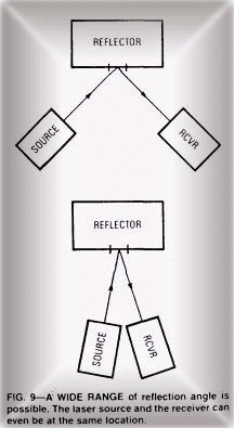
To use the receiver as a remote sound pickup, you will need a laser and a reflective surface that sound waves will cause to vibrate; the receiver must be positioned so it can "catch" the direct reflection of the laser beam (Fig. 9).
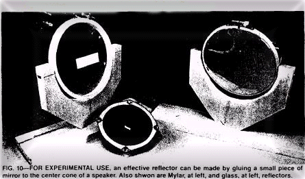
A particularly effective reflector for experimental use is a small piece of mirror (about 1/4 x 3/4 inch) cemented to the center of a speaker cone (see Fig. 10).
There is no connection made to the speaker. The movement of the speaker cone caused by sound waves is transferred to the mirror-reflector. Which in turn modulates the laser beam. Due to the varying reflectivety and distances of the targets, the intensity of the light falling upon the detector may vary considerably from setup to setup. That will be readily apparent if the collector voltage of Q1 is measured while the illumination level on Q1 is adjusted. At some point of increasing illumination, the collector voltage will fall sharply and the audio output from the receiver will drop or disappear. The small-diameter polarized filter should then placed over Q1. If more light attenuation is required, slip the large-diameter filter in position and rotate it for maximum sound output.
Thin is in
The thinner and more responsive to sound the reflective medium is. The greater the laser bug's sensitivity. Most window panes will work. Moving the beam to different spots on the glass can make a dramatic difference in the sensitivity. For testing, no additional optics are needed for the receiver, Set up any convenient reflector-the mirrored speaker. or even an embroidery hoop holding plastic wrap or Mylar film (see Fig. 10) aim the laser at the reflector, and then position the reflector so that the beam bounces back to the receiver. If you speak in the room, or play a radio or a tape recorder, the sound will be heard in the receiver's headphones. Another test can be done by modulating the laser with a 1 kHz tone while having an assistant move the target reflector for maximum tone reception as indicated by maximum volume in the highest meter reading. A non-adjustable target, such as a window pane, requires that the operator select a site where a direct reflection can be caught. That can be done from hundreds of feet away if conditions are right. Use the modulated beam for setup, and then remove the modulation to listen in. Double-pane glass and storm windows tend to greatly reduce sound transmission to the outer glass. It is possible, however, to aim through the glass to an object within the room, such as the glass front of a china cabinet or a hanging picture. The returned reflection is usually modulated.
At long range
At ranges greater than 100 feet or so, or when a high ambient light level obscures the reflected beam, a means must be provided to accurately aim the receiver to the reflected laser.
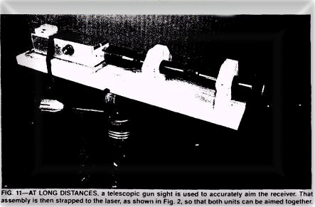
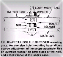
As shown in Fig. 11, the receiving unit of our prototype laserbug system uses a telescopic gunsight; and that assembly is, in turn, mounted directly on the laser housing as shown in Fig. 2 so both the laser and receiver can be aimed as a single unit. The design of a combination receiver and laser mounting bracket will depend on the particular laser and scope that's being used. In general, the mounting bracket should be sturdy and have provisions for coarse elevation and azimuth adjustments; all gun scopes have provisions for fine adjustments. The adjustment details for the prototype mount are shown in Fig. 12.
The scope-to-laser alignment is done in two stages, First, the distance from the center of the laser beam to the center of the scope is measured and used as the spacing for the cross marks of the target shown in Fig. 13,
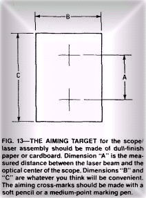
which is made from dull, white cardboard. Then, the target is taped to a wall about 50 feet away from the laser assembly. Next, with the scope's cross-hair adjustments at the center of their range, position the laser beam at the center of the lower cross. Looking through the scope, adjust the scope's mounting bracket so that its cross-hairs are close to being centered on the target's upper mark. Making sure that the laser beam stays centered on the lower mark, tighten the mounting bracket's nuts and use the scope's fine adjustments for the final alignment. In this instance, the diffuse reflection of the laser beam from the card should present no eye hazard. When using the laser/scope assembly, remember that at a range of under 300 feet you must compensate for the aiming error introduced by the offset between the scope and the laser beam centerlines. Again, let us stress that under no circumstances should the laser beam or its direct reflection be viewed through optical devices of this type because severe damage to the eye can result.