|
|
|
Motorola 900MHz PAs...
"300W"
"150W"
300W Motorola 900MHz PA
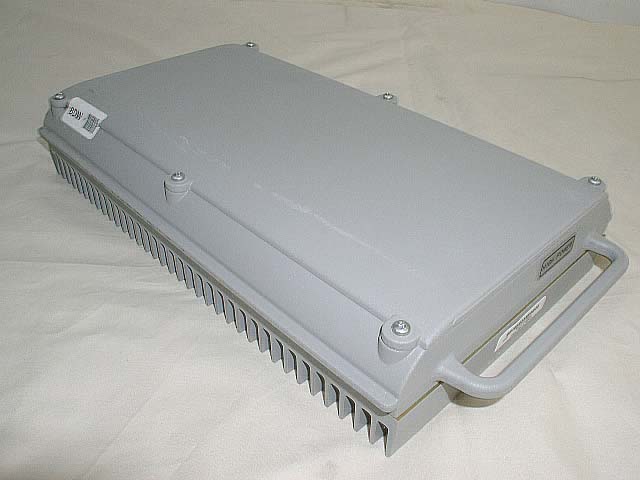 This PA uses two
MRF899 power transistors, driven by two MRF897s. The specifications show the MRF899 rated for
28VDC max, and the MRF897 for 26VDC max (2V less "nominal"). See specifications, below. The
PA is very easy to convert to amateur use, requiring addition of only two RF connectors, 20+A
24VDC connectors, and a PTT port. With only 4.5W drive available, and a 26V @ 20A power
supply, 230W continuous output was reported. This PA is self-limited to about 250W maximum
output by the internal control board. Adventuresome folks who have removed the control board
and are powering the PA boards directly have tested this unit with 27 and 28VDC power supplies,
but only for short periods; it is not known how long the transistors would last if supplied directly
with more than 26V DC. Leaving the control board in place assures voltage regulated to 24VDC
will be applied to the PA boards, alleviating any concerns regarding overvoltage!! This PA uses two
MRF899 power transistors, driven by two MRF897s. The specifications show the MRF899 rated for
28VDC max, and the MRF897 for 26VDC max (2V less "nominal"). See specifications, below. The
PA is very easy to convert to amateur use, requiring addition of only two RF connectors, 20+A
24VDC connectors, and a PTT port. With only 4.5W drive available, and a 26V @ 20A power
supply, 230W continuous output was reported. This PA is self-limited to about 250W maximum
output by the internal control board. Adventuresome folks who have removed the control board
and are powering the PA boards directly have tested this unit with 27 and 28VDC power supplies,
but only for short periods; it is not known how long the transistors would last if supplied directly
with more than 26V DC. Leaving the control board in place assures voltage regulated to 24VDC
will be applied to the PA boards, alleviating any concerns regarding overvoltage!!
MRF899: NPN Silicon RF Power Transistor Specs:
Designed for 26 Volt UHF large signal, common emitter, Class AB linear amplifier applications
in industrial and commercial FM/AM equipment operating in the range 800-960 MHz.
Specified 26 Volt, 900 MHz Characteristics Output Power = 150 Watts (PEP) Minimum Gain = 8.0
dB @ 900 MHz, Class AB Minimum Efficiency = 35% @ 900 MHz, 150 Watts (PEP) Maximum
Intermodulation Distortion 28 dBc @ 150 Watts (PEP)
Max permissible voltage 28VDC
MRF897: NPN Silicon RF Power Transistor Specs:
Designed for 24 Volt UHF large signal, common emitter, classAB linear amplifier applications
in industrial and commercial FM/AM equipment operating in the range 800-970 MHz.
Specified 24 Volt, 900 MHz Characteristics Output Power = 30 Watts Minimum Gain = 10 dB @ 900
MHz, class AB Minimum Efficiency = 30% @ 900 MHz, 30 Watts (PEP) Maximum Intermodulation
Distortion 30 dBc @ 30 Watts (PEP)
Max permissible voltage 26VDC
Click on pictures for zoom
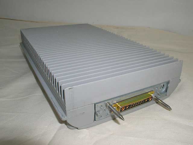
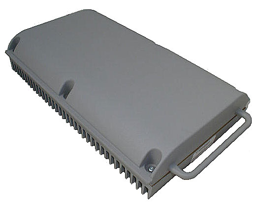
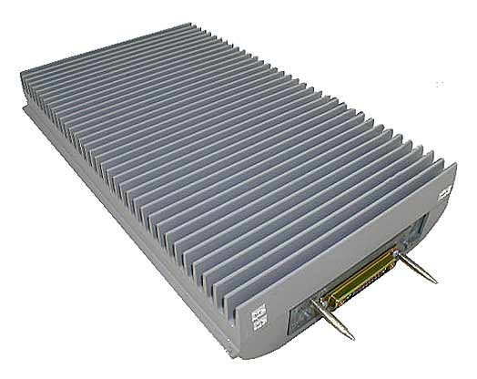
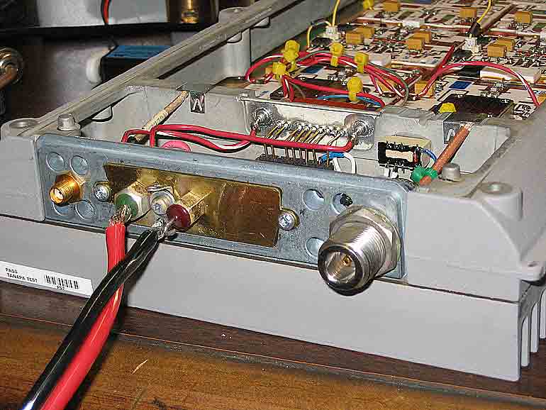
Connector end, unmodified PA
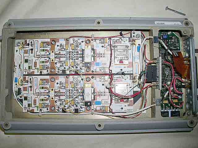
Inside unmodified PA
KD5FZX conversion
1. Replace the in and output connectors with connectors of your choice.
Picture
2. Break the bias power and connect it through a relay contact.
Picture
3. If you need more than 250W output, then bridge the 0.02ohm surface mount resistor next to
J5 on the control board.
Click on pictures for zoom
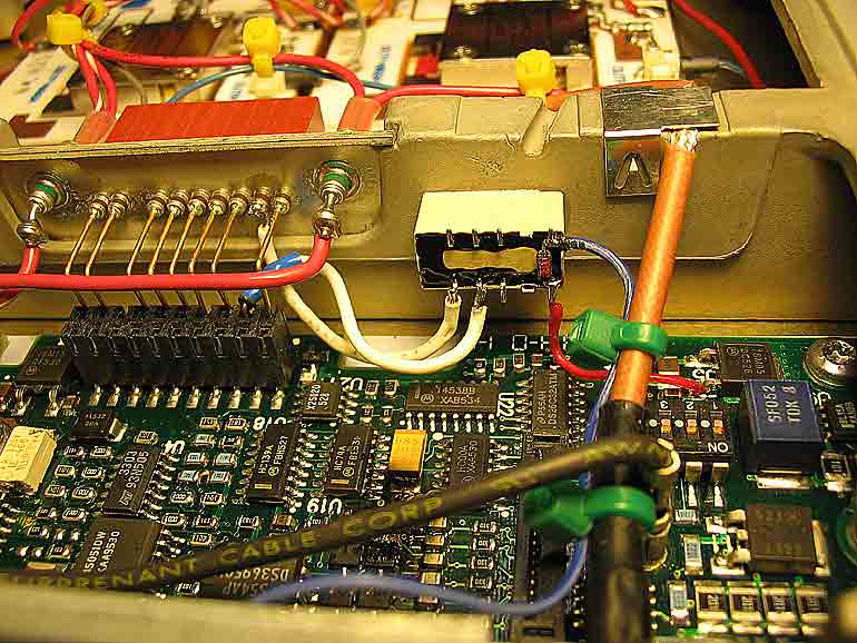
Control board end of mod'd PA
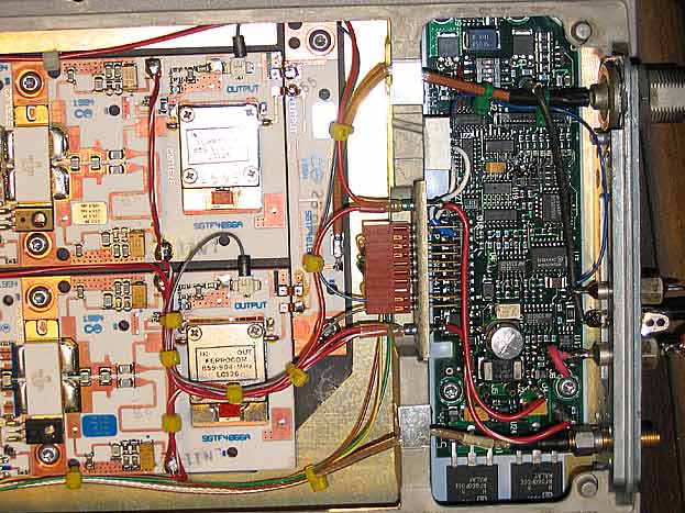
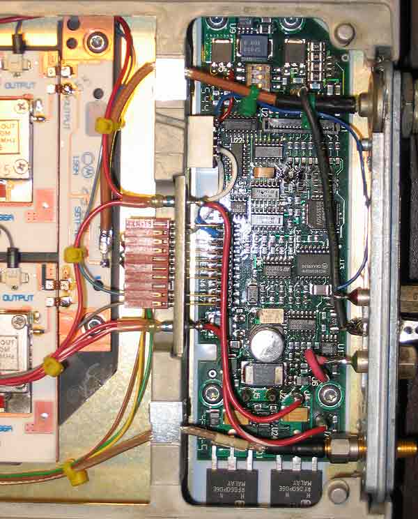
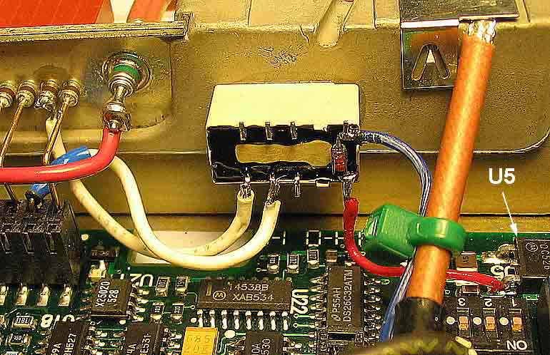
Closeup, PA control board
I used a small relay with 5V coil connected to the 5V regulator U5
(Picture). Ground the other side of
the coil to enable bias. The 0.02ohm resistor is used to measure the total collector
current, and will limit the output to 250W. Bridge this resistor to disable this
limitation. I decided to stay at 250W (HP measurement) and keep the limit in place to
protect the transistors. If you keep this safety in place and overdrive the amp, then
you will notice severe distortion from this circuit switching the bias on and off at the
current limit.
150W Motorola 900MHz PA
There are also "150W" version of this PA in existence. They look almost identical from the
outside (seepictures below - click for zoom), but are different on the inside.
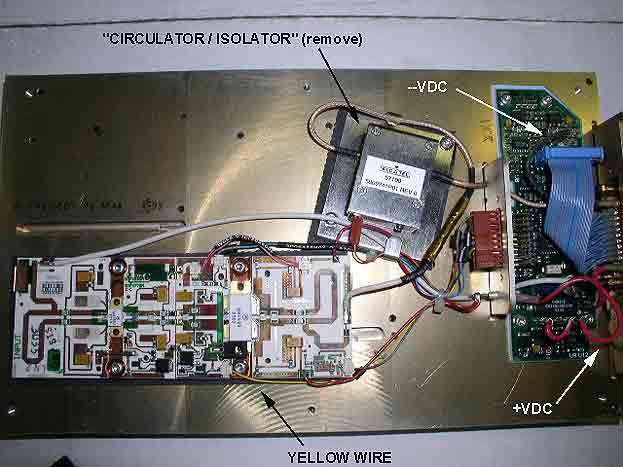
The power wires are pretty easy to pick out, but note that the "enable" line is the yellow
wire. It calls for +15 volts, but we are told that +13.6V will do the job. Additionally,
there is a little silver box on the ouput - we have been told that this circulator/isolator
will not pass 902-3MHz, and it should be removed. AA9IL, howevr, has left it in his and is
getting full output with the isolator still installed. We have no test data to determine if
some are slightly different from some others. This page will be updated when such data becomes
available. See picture below (click for zoom):
Web site and all contents © Copyright VHFSouth 2006,
All rights reserved.
|
|
